2
Backbone®Media Platform
Assembly Instructions
Assemble units as described herein only. To do otherwise
may result in instability. All screws, nuts and bolts must be
tightened securely and must be checked periodically after
assembly. Failure to assemble properly, or to secure parts
may result in assembly failure and personal injury.
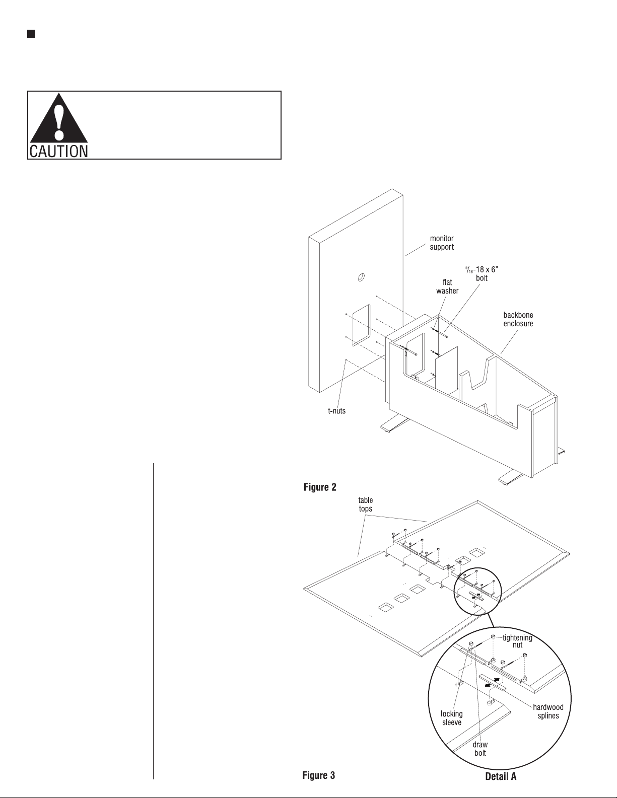
Optional Monitor Support
Attachment
7. Locate hardware kit
#47.0817, shipped with
Monitor Support. Begin by
removing the six screws
which secure the perforated
steel panel to the inside of
the Backbone enclosure to
gain better access.
8. Move the monitor support
into position behind the
Backbone enclosure as
illustrated. Locate the six
5/16–18 x 6” bolts from the
hardware kit and place a flat
washer on each of the bolts.
Insert the bolts through the
interior of the enclosure
unit and into the T-nuts in
the monitor support front
panel. To do so, the monitor
support will need to be
elevated ½” or so. Leave
each bolt loose until all six
are threaded into the monitor
support front panel. After
all six bolts are threaded
in, square the bottom of
the support to the floor and
tighten all six bolts to secure
(Figure 2).
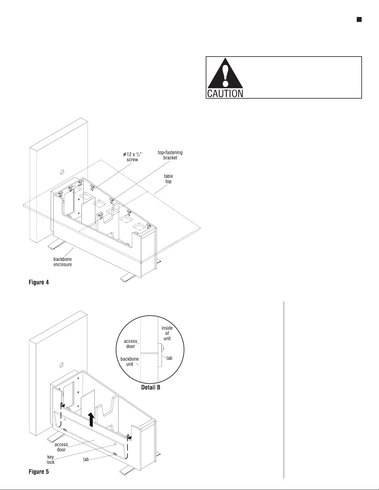
Table Top Assembly
Installation
9. Take care to protect table top
sections from damage and
place both tops upside down
onto a soft, flat protective
surface. Insert hardwood
splines into slots in table
top, then carefully move the
table tops closer together
and insert barrel fastener
components (locking sleeve,
draw bolt & tightening nut)
into underside of table top
as illustrated. Align the
fasteners and the hardwood
splines, while gently moving
the two tops together. Next,
start the draw bolts into the
round threaded ends of the
tightening nut by using the
1/8” diameter by 4” long tool
provided. Tighten all barrel
fasteners, small amounts at
a time to draw tops together,
but do not tighten completely
at this time. Once all barrel
fasteners are attached,
flush the outer edge of each
table top half and tighten
all fasteners to secure. Be
careful to keep table halves
aligned, and to not pinch
the protective surface in the
seam from the underside
of assembly (Figure 3 &
Detail A).
Note: Top assemblies and
enclosure units are labeled as
sets with letters in the factory.
Take care to match like-labeled
components together during
assembly of multiple unit
installations.