UCHIDA AeroCut X User manual

SERVICE MANUAL
UCHIDA YOKO CO., LTD., TOKYO, JAPAN
V1.00

AeroCut X / XPro SERVICE MANUAL
2
Contents
1Installation....................................................................................................4
1.1 Installing options(AeroCut X)............................................................. 4
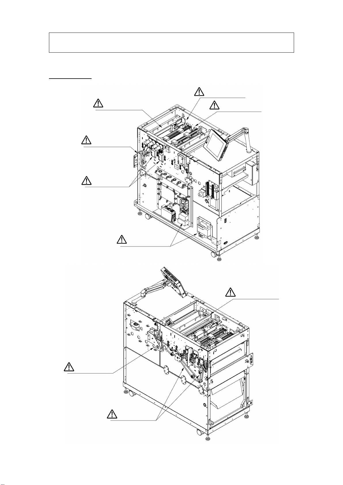
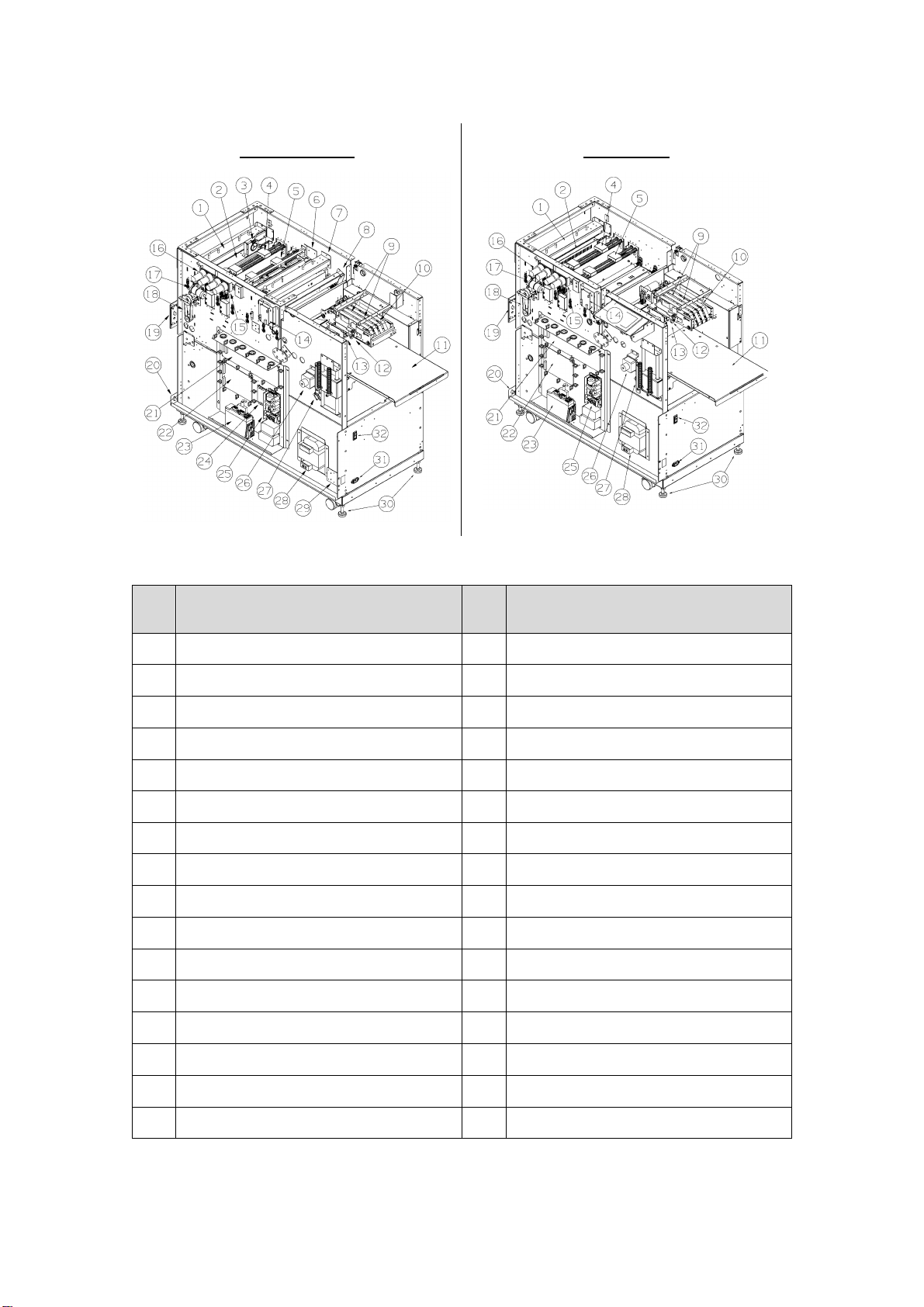
2General instruction .......................................................................................6
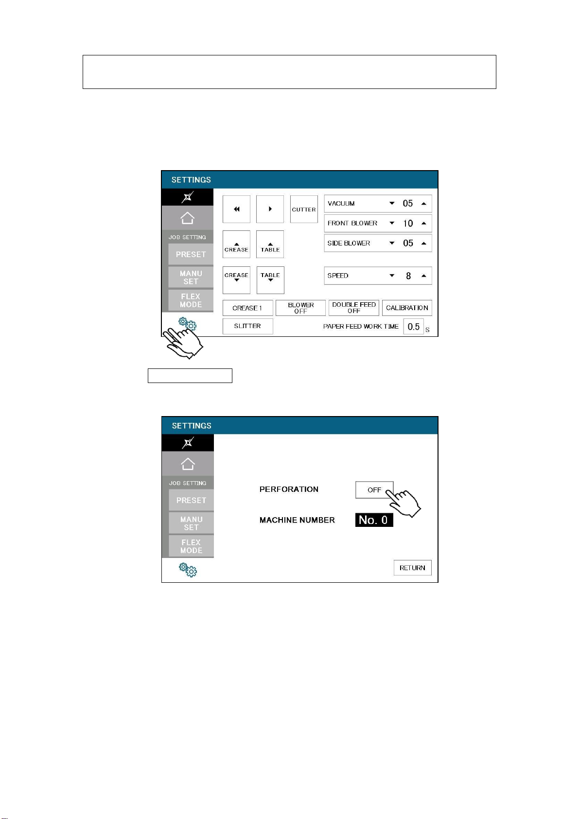
3Touch screen operation..............................................................................12
3.1 SERVICE MENU.................................................................................. 12
3.2 MANUAL OPERATION Screen ............................................................14
3.3 SPEED Screen ....................................................................................18
3.4 SLITTER Operation Screen .................................................................18
3.5 INPUT DATA CHECK Screen...............................................................19
3.6 LANGUAGE Screen.............................................................................26
3.7 MAINTENANCE Screen ......................................................................27
4Paper jam...................................................................................................29
5Replacement of parts ................................................................................. 31
5.1 Slitter Unit ............................................................................................ 31
5.2 Slitter head...........................................................................................33
5.3 Guillotine Unit.......................................................................................36
5.4 X-perforator blade ................................................................................37
5.5 Y-perforator blade ................................................................................ 39
5.6 Feed belt Unit.......................................................................................40
6Adjustment .................................................................................................42
6.1 Settings................................................................................................ 42
6.1.1 Feed settings.................................................................................42
6.1.2 Accuracy adjustment .....................................................................43
6.2 Feed unit adjustment ........................................................................... 44
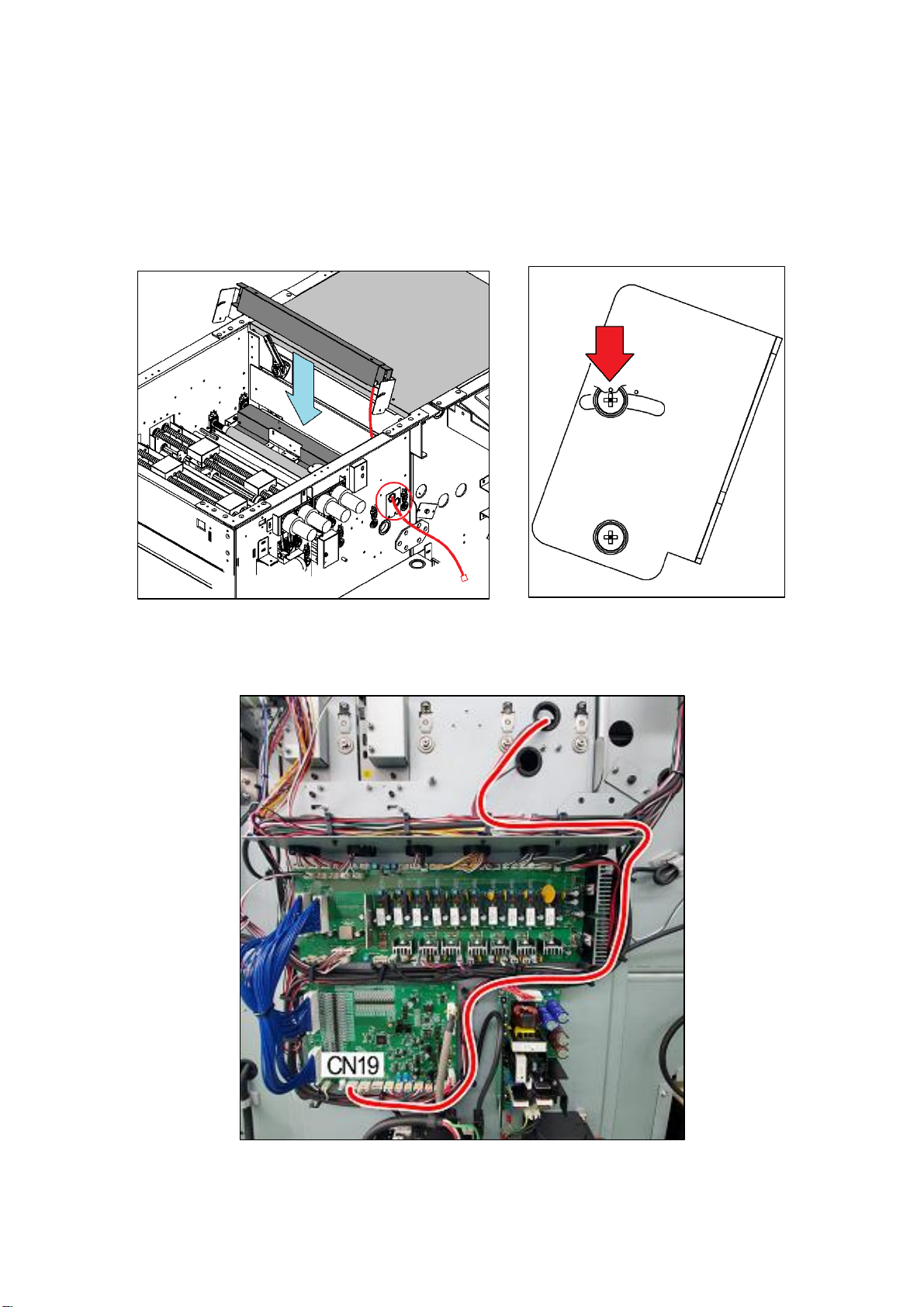
6.3 Electrical equipment.............................................................................51
6.3.1 CPU board.....................................................................................51
6.3.2 I/O board........................................................................................52
6.3.3 Sensor PCB...................................................................................53
6.3.4 Cut mark sensor ............................................................................54
6.3.5 Ultra-sonic PCB .............................................................................55

AeroCut X / XPro SERVICE MANUAL
3
7How to make layout....................................................................................56
7.1 General template(mm) .........................................................................56
7.2 General template(inch) ........................................................................ 57
7.3 How to use barcode .............................................................................58
8Electricity related........................................................................................66
8.1 Equipment, Electric circuit, and parts................................................... 66
8.2 Board Details ....................................................................................... 72
8.3 Input / Output LED Details ...................................................................76
8.4 Tap Voltage Details ..............................................................................79
8.5 Wiring Details.......................................................................................81
8.6 Servo motor driver setting.................................................................... 83
9Program update .........................................................................................85
9.1 Software install..................................................................................... 85
9.1.1 Requirements ................................................................................85
9.1.2 Confirmation of Accessories .......................................................... 85
9.1.3 How to install Transfer Tool (Touch screen for XPro) ..................... 86
9.1.4 How to install “AVR STUDIO” ........................................................87
9.2 Touch screen........................................................................................91
9.3 CPU board ...........................................................................................97
10 Cleaning & greasing................................................................................. 103
11 Recommended replacement parts ........................................................... 104
12 Troubleshooting ....................................................................................... 106
Record of change
No.
Date
Contents of change
Expected date
to change
5
4
3
2
1

AeroCut X / XPro SERVICE MANUAL
4
1 Installation
1.1Installing options(AeroCut X)
(a) Y-perforator
①Double tap on bottom left corner of SETTINGS screen.
②Activate PERFORATION
OFF → ON
③Reboot the machine before use.

AeroCut X / XPro SERVICE MANUAL
5
(b) Barcode reader
①Attach the Barcode Reading Kit to the machine.
②Fix the Barcode Reading Kit so that a hole on left side will be placed
towards the top.
③Position should be as below picture.
④Connect the cables according to the red line as shown on below picture.
⑤The Barcode Reading Kit should be connected to CN19 on the CPU board.

AeroCut X / XPro SERVICE MANUAL
6
2 General instruction
(a) Caution
AeroCut XPro
Guillotine blades
Slitter blades
Creaser
Timing belt
High voltage
Perforator blade
Timing belts
Chain
Gears

AeroCut X / XPro SERVICE MANUAL
7
AeroCut X
Guillotine blades
Slitter blades
Creaser
Timing belt
High voltage
Timing belts
Gears

AeroCut X / XPro SERVICE MANUAL
8
(b) Necessary tools
C-clip ring pliers
Feeler gauge
USB cable
Type A / mini B
SD card
To replace slitter
blades
For clutch
For Software install
Maintenance kit
Program update tool
Pipe
Roller remover
To replace slitter blades
To cleaning roller
(c) Factory setting
・Factory setting sheet is attached inside of the front cover.

AeroCut X / XPro SERVICE MANUAL
9
(d) Remove covers

AeroCut X / XPro SERVICE MANUAL
10
(e) Names of parts
AeroCut XPro
AeroCut X
No.
Name
No.
Name
01
Creaser
17
Guillotine motor
02
Guillotine(Cutter)
18
Timing belt
03
Ionizer
19
Conveyor connector
04
Gutter slitter unit
20
Waste conveyor connector
05
Margin slitter unit
21
PCB (I/O board)
06
Y-perforator
22
PCB (CPU board)
07
X-perforator
23
Servo amplifier
08
Barcode reading unit
24
PCB (Sensor)
09
Fan motor (Suction)
25
DC power supply
10
Feed belts
26
Feed table motor
11
Feed table
27
Micro switch (Feed table lower limit)
12
Feed sensor
28
Transformer
13
Fan motor (Blow)
29
LAN connector
14
PCB (Ultra-sonic sensor)
30
Caster
15
Margin slitter motor
31
Inlet
16
Gutter slitter motor
32
Power switch

AeroCut X / XPro SERVICE MANUAL
11
AeroCut XPro
AeroCut X
No.
Name
No.
Name
01
Monitor arm
09
Timing belts
02
Touch screen
10
Cover sensor
03
X-perfo motor
11
Sponge roller
04
Y-perfo head (Solenoid)
12
Carrying roller
05
Fan motor (Side Blow)
13
Crease motor
06
Cover sensor
14
Main motor
07
Clutch
15
Feed motor
08
Encoder

AeroCut X / XPro SERVICE MANUAL
12
3 Touch screen operation
3.1SERVICE MENU
AeroCut XPro
Press and hold the top left corner
until hear a sound.
Press and hold the bottom left corner
until the screen changes
AeroCut X
Click the upper left corner 5 times.

AeroCut X / XPro SERVICE MANUAL
13
Double click the top left corner.
Enter the service password.
Program Version
TP-V stands for Version of the Touch screen image.
CPU-V stands for Version of the CPU board program.

AeroCut X / XPro SERVICE MANUAL
14
3.2MANUAL OPERATION Screen
AeroCut XPro
①
Carrying roller will rotate.
②
Carrying roller will rotate. (Continuous)
③
The speed of Carrying roller can be adjusted to two levels (SLOW or FAST).
④
Carrying rollers will rotate at input length. [mm]
⑤
Enter the dimension of Fixed feed.
⑥
X-Perfo blade will move toward far side from an operator.
⑦
X-Perfo blade will move toward near side from an operator.
⑧
X-Perfo blade will move to specified point .[mm]
⑨
Input moving distance of X-Perfo blade.[mm]
⑩
Guillotine will move once.
⑪
Crease will move upper limit.
⑫
Crease will move lower limit.
⑬
X-Perfo blade will move to initial position.
⑭
FEED TABLE will move upward while this is being pressed.
⑮
FEED TABLE will move downward while this is being pressed.
⑯
Go to SLITTER Operation Screen.
⑰
Go to INPUT DATA CHECK screen.
⑱
SV OFF: the state where the servo motor does not respond to any orders.
SV ON: the state where the servo motor responds to all orders.
⑲
Go to SPEED screen.
⑳
Vacuum motor will be turned ON and OFF.
㉑
Blow motor will be turned ON and OFF.
㉒
Counter for servo movement.

AeroCut X / XPro SERVICE MANUAL
15
㉓
Reset the counter for servo movement to zero.
㉔
Switch ON/OFF of each Y-Perfo
㉕
Double Feed Detection
Transmittance of the double feed sensor is shown as an integer between 0 and
1023. The umber 1023 represents the state in which there is no sheet under the
sensor, while the number closer to zero indicates that thicker sheets have been
detected by the sensor.
: paper sheets are being loaded.
: no paper sheets loaded.
㉖
Check operation of X-Perfo. Count times of operation.
㉗
Check operation of jump function of Y-Perfo. Count times of jumping.
㉘
Stop all operations. Of note, Cutter and Crease will move to the upper limit.
㉙
Return to SERVICE MENU Screen.

AeroCut X / XPro SERVICE MANUAL
16
AeroCut X
①
SV OFF: the state where the servo motor does not respond to any orders.
SV ON: the state where the servo motor responds to all orders.
②
Carrying roller will rotate.
③
Carrying roller will rotate. (Continuous)
④
The speed of Carrying roller can be adjusted to two levels (SLOW or FAST).
⑤
Adjustable the carrying speed.
⑥
Carrying rollers will rotate at input length. [mm]
⑦
Enter the dimension of Fixed feed.
⑧
Counter for servo movement.
⑨
Reset the counter for servo movement to zero.
⑩
Guillotine will move once.
⑪
Crease will move upper limit.
⑫
Crease will move lower limit.
⑬
FEED TABLE will move upward while this is being pressed.
⑭
FEED TABLE will move downward while this is being pressed.
⑮
Go to SLITTER Operation Screen.
⑯
Stop all operations. Of note, Cutter and Crease will move to the upper limit.
⑰
<<:Feed belt will rotate positively by pressing this once.
It will stop by pressing it again.
>>:Feed belt will rotate negatively by pressing this once.
It will stop by pressing it again.
⑱
Vacuum motor will be turned ON and OFF.
⑲
Adjustable the Vacuum pressure.
⑳
Blow motor will be turned ON and OFF.
㉑
Adjustable the Front Blower pressure.
㉒
Adjustable the Side Blower pressure.
㉓
Go to INPUT DATA CHECK screen.
㉔
Double Feed Detection

AeroCut X / XPro SERVICE MANUAL
17
Transmittance of the double feed sensor is shown as an integer between 0 and
1023. The umber 1023 represents the state in which there is no sheet under the
sensor, while the number closer to zero indicates that thicker sheets have been
detected by the sensor.
: paper sheets are being loaded.
: no paper sheets loaded.
㉕
Return to SERVICE MENU Screen.

AeroCut X / XPro SERVICE MANUAL
18
3.3SPEED Screen
AeroCut XPro
・Regarding suction adjustment and speed change, refer to “5.1 Adjustments
on the paper feed” in Operation Manual.
・
3.4SLITTER Operation Screen
AeroCut XPro
AeroCut XPro
・Values
The values of Slitter’s current positions are shown.
・ ,
:Slitters will move to the end while this is being pressed.
:Slitters will move to the front while this is being pressed.
・ RETURN
Return to Manual Operation Screen.

AeroCut X / XPro SERVICE MANUAL
19
3.5INPUT DATA CHECK Screen
AeroCut XPro
:OFF :ON
AeroCut X
:OFF :ON
① PPR L/EDGE SENS 1(Origin sensor)
The sensor lamp will be turned off when shielded
and turned on when transmitted.
The lamp on the screen will be turned on when
shielded and turned off when transmitted.
② C/MARK SENS(Cut mark sensor)
The sensor lamp (orange) will be turned on when
detecting black color and turned off with no
detection.
The lamp on the screen will be turned on when
detecting black color and turned off with no
detection.
How to adjust. (Page54)

AeroCut X / XPro SERVICE MANUAL
20
③ PPR L/EDGE SENS 2(Stop sensor)
The sensor lamp will be turned on when shielded
and turned off when transmitted.
The lamp on the screen will be turned on when
shielded and turned off when transmitted.
How to adjust. (Page51 or Page53)
AeroCut XPro
AeroCut X
④ CUTTER UP/LMT SW
The lamp on the screen will be turned on when the
switch is on.
This manual suits for next models
1
Table of contents
Other UCHIDA Office Equipment manuals
Popular Office Equipment manuals by other brands

Steelcase
Steelcase Turnstone Small Office Solution Set Assembly instructions

OCEE DESIGN
OCEE DESIGN DEN SASS-0082 Assembly instructions

Formax
Formax FD 210M Operator's manual

Framery
Framery O VCR Troubleshooting instructions

Steelcase
Steelcase Avenir PAB-4 Joining Panel manual

PolyVision
PolyVision Collaborative ToolBar instruction manual