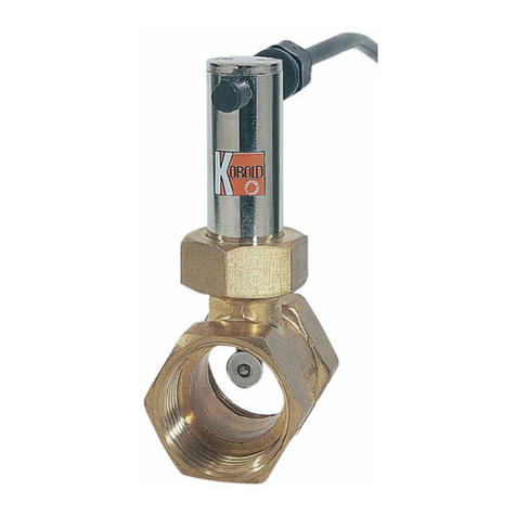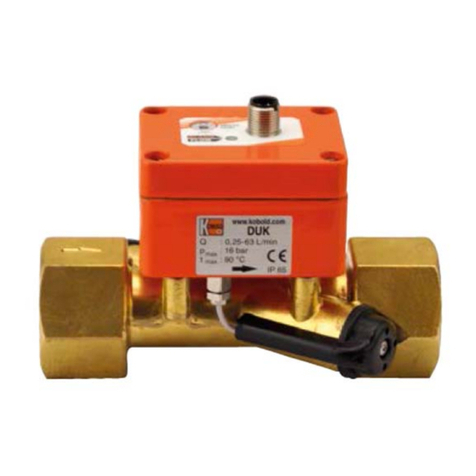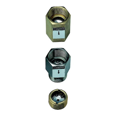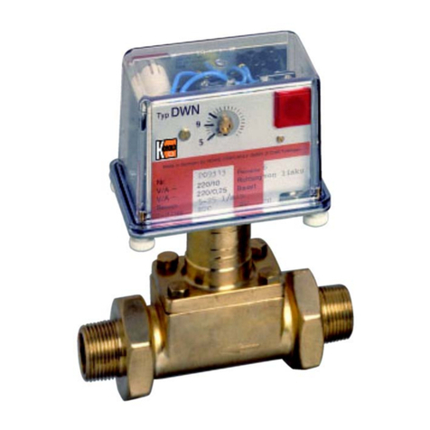
TSK1 Installation and Operating Instructions
Page 2 of 30
Contents
1INTRODUCTION ............................................................................................................................................................ 4
2IDENTIFICATION........................................................................................................................................................... 4
2.1 Supplier/manufacturer............................................................................................................................................... 4
2.2 Product type............................................................................................................................................................... 4
2.3 Product name............................................................................................................................................................. 4
2.4 Issue date................................................................................................................................................................... 4
2.5 Version no.................................................................................................................................................................. 4
3APPLICATIONS............................................................................................................................................................. 4
4SAFETY INSTRUCTIONS.............................................................................................................................................. 4
4.1 Intended use............................................................................................................................................................... 4
4.2 Installation, start-up and operating personnel......................................................................................................... 4
4.3 Packaging / Storage / Transportation....................................................................................................................... 5
5OPERATIONAL MODE AND SYSTEM DESIGN............................................................................................................ 5
5.1 Measuring principle................................................................................................................................................... 5
5.2 System design ........................................................................................................................................................... 5
6INPUT............................................................................................................................................................................. 6
6.1 Measured variable...................................................................................................................................................... 6
6.2 Measuring range (lower-range and upper-range value).......................................................................................... 6
6.3 Measuring range table............................................................................................................................................... 6
7OUTPUT SIGNALS ........................................................................................................................................................ 6
7.1 Binary output ............................................................................................................................................................. 6
7.1.1 KEI1 or KEI2 limit switches.............................................................................................................................. 6
7.1.2 KEM1 or KEM2 limit switches (special version) ............................................................................................... 7
7.2 Analog output with the ES magneto-electric transmitter........................................................................................ 7
7.3 Typ ES-PPA and ES-FF.............................................................................................................................................. 7
8CHARACTERISTIC VALUES......................................................................................................................................... 7
8.1 Measuring Accuracy.................................................................................................................................................. 7
8.1.1 Reference conditions....................................................................................................................................... 7
8.1.2 Measured error................................................................................................................................................ 7
8.1.3 Repeatability ................................................................................................................................................... 7
8.2 Influence of ambient temperature............................................................................................................................. 7
8.3 Influence of media temperature................................................................................................................................ 7
9CONDITIONS OF USE................................................................................................................................................... 7
9.1 Installation conditions............................................................................................................................................... 8
9.1.1 Mounting/start-up ............................................................................................................................................ 9
9.1.2 Device settings.............................................................................................................................................. 10
9.1.3 Switchpoint adjustment on inductive limit switches KEI................................................................................. 10
9.1.4 Adjustment of KEM1 / KEM2 Microswitches.................................................................................................. 10
9.1.5 Operation in hazardous areas ....................................................................................................................... 11
9.2 Ambient conditions ................................................................................................................................................. 12
9.2.1 Ambient temperature limits............................................................................................................................ 12
9.2.2 Storage temperature ..................................................................................................................................... 12
9.2.3 Climatic category........................................................................................................................................... 12
9.2.4 Degree of protection...................................................................................................................................... 12
9.2.5 Shock resistance/vibration resistance............................................................................................................ 12
9.2.6 Electromagnetic compatibility........................................................................................................................ 13
9.3 Fluid conditions....................................................................................................................................................... 13
9.3.1 Fluid temperature limits................................................................................................................................. 13
9.3.2 Diagram: Max. ambient temperature based on fluid temperature for sensor ES............................................ 13
9.3.3 Media Pressure limit...................................................................................................................................... 13
9.3.4 Physical state................................................................................................................................................ 13
9.3.5 Density.......................................................................................................................................................... 13
9.3.6 Pressure loss ................................................................................................................................................ 13
10 DESIGN DETAILS........................................................................................................................................................ 14
10.1 Type of construction / dimensions......................................................................................................................... 14
10.1.1 Indicator housing Aluminum .......................................................................................................................... 14
10.1.2 Indicator housing stainless steel.................................................................................................................... 15
10.2 Dimensions TSK-C, TSK-S, TSK H.......................................................................................................................... 17
