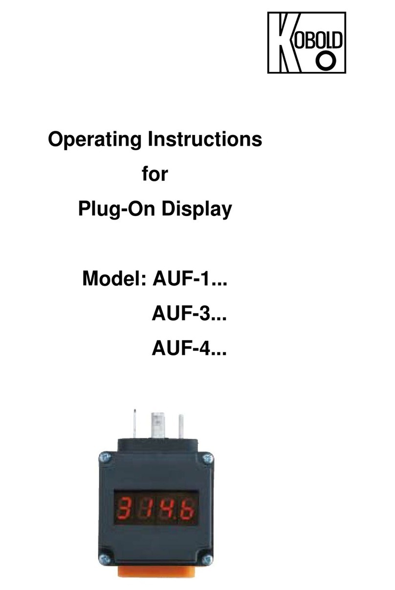
Type: AUF 08/98
6.7. Direction of Switching (type AUF-1001, optional)
Press button B until: d i r is displayed.
⇒A+B menu item for setting: d n
(Hysteresis above switch point; inverse)
⇒B or A for up and down: u p
(Hysteresis below switch point)
⇒A+B acknowledge the setting and return to menu item “dir”
6.8 Return to Measuring Mode
Press key A or B one to eight times depending on the selected menu item.
7. Declaration of Conformance
We, Kobold-Messring GmbH, Hofheim-Ts., Germany,
declare under our sole responsibility that the product
Plug-on Display Model AUF-
to which this declaration relates is in conformity with the standards noted
below:
EN 50081-1
EMC General Emission Requirements
EN 50082-2
EMC General Immunity Requirements
following the provision of European Directives:
89/336/EWG
Signed: Date: 12.08.98
Name: R.Wenker
Manufacture and Sales
KOBOLD Messring GmbH Tel.: 06192-299-0
Nordring 22–24 Fax: 06192-23398
D-65719 Hofheim
Operating Instructions for Plug-On Display Model AUF-
1. Note
Read these operating instructions before unpacking and initial operation, and follow them
carefully. The devices should only be used, serviced, and repaired, by persons who are familiar
with the operating instructions and with valid regulations for safety and accident prevention.
2. Specific Application
The model AUF-1000 and AUF-1001 plug-on display is a universal local display suitable for
use with various transmitters. The transmitter must be fitted with an analog output and a con-
nector in accordance with DIN 43 650. The plug-on display is simply plugged in between con-
nector and socket; it is then ready for operation. Having removed the cover, scaling, the position
of the decimal point, damping and switch point (typ AUF-1001, optional) may be set with two
keys. The menu steps are indicated on the LED display.
3. Instrument Inspection
The devices are inspected before they are sent out; they are then dispatched in perfect working
order. Should there be any visible damage to the device, we recommend to examine the delivery
packaging carefully. Immediately inform the parcel service or forwarding agency in the event of
a claim, as the haulier is responsible for damage in transit.
4. Mechanical Connection
The plug-on display is simply plugged in between connector and socket; it is then ready for op-
eration. The fixing screw must be replaced with the longer screw that is part of the delivery
scope. The display can be rotated in 90°-steps.
5. Electrical Connection
Connect the plug-on display as shown in the wiring diagram.
UB+ = PIN 1
0 V = PIN 2
Switching output = PIN 3
Connect PIN 2 and PIN 3 for devices with open-collector out-
put (Type AUF-1001), PNP, max. current load 90 mA
Alarm on (right decimal point is flashing)
Alarm off (right decimal point is off)
Alarm off (right decimal point is off)
Alarm on (right decimal point is flashing) Direction of switching dn (invers)
Hysteresis
Hysteresis
Dircetion of switching up
P
P
HYS = 20,3
Spt = 20,0
Spt = 20,0
HYS = 19,7
t
t
max. current load 60 mA
