Kobold KAL-K User manual

Operating Instruction
for
Electronic Flow Monitor
Compact Version
Model: KAL-K

KAL-K
Page 2 KAL-K K03/0516
1. Contents
1.Contents........................................................................................................2
2.Note ..............................................................................................................3
3.Instrument Inspection....................................................................................3
4.Regulation Use..............................................................................................3
5.Operating Principle........................................................................................4
6.Mechanical Connection.................................................................................5
7.Electrical Connection and Operational Elements..........................................5
8.Characteristics ..............................................................................................7
9.Output Characteristic (only for 24 VDC) .........................................................8
10.Commissioning..............................................................................................9
11.Maintenance ...............................................................................................10
12.Technical Information..................................................................................11
13.KAL-K Diagnostics......................................................................................12
14.Order Codes ...............................................................................................12
15.Spare parts .................................................................................................12
16.Dimensions .................................................................................................13
17.EU Declaration of Conformance..................................................................15
Manufactured and sold by:
Kobold Messring GmbH
Nordring 22-24
D-65719 Hofheim
Tel.: +49(0)6192-2990
Fax: +49(0)6192-23398
Internet: www.kobold.com

KAL-K
KAL-K K03/0516 Page 3
2. Note
Please read these operating instructions before unpacking and putting the unit
into operation. Follow the instructions precisely as described herein.
The devices are only to be used, maintained and serviced by persons familiar
with these operating instructions and in accordance with local regulations
applying to Health & Safety and prevention of accidents.
When used in machines, the measuring unit should be used only when the
machines fulfil the EC-machine guidelines.
3.Instrument Inspection
Instruments are inspected before shipping and sent out in perfect condition.
Should damage to a device be visible, we recommend a thorough inspection of
the delivery packaging. In case of damage, please inform your parcel service /
forwarding agent immediately, since they are responsible for damages during
transit.
Scope of delivery:
The standard delivery includes:
Electronic Flow Monitor, Compact Version model: KAL-K
Operating Instructions
4. Regulation Use
The KOBOLD KAL-K Flow Monitor is intended for use in monitoring and control
applications involving moderate flow rates of low-viscous or dirty liquids.
Limiting Signal
The devices are equipped with NPN or PNP signals (24 VDC- power supply) or
relay (110 VDC, 110 VAC, 230 VAC power supply) for monitoring the flow velocity of
liquids.
Trend Display
A LED bar graph display indicates the current flow rate and the set point via a
flashing LED.

KAL-K
Page 4 KAL-K K03/0516
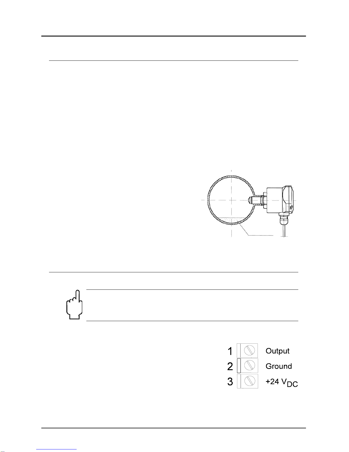
Sensor
The model KAL-K consists of a sensor with integrated electronic.
The devices may only be used for liquids to which the probe material is resistant.
With proper installation and maintenance, the probes are not sensitive to soiling
and cause practically no pressure loss.
Materials
Sensor Stainless steel (1.4301, 1.4305, 1.4571)
Electronic housing Polyamide (glass fibre reinforced)
Setting ranges
in relation to nominal tube diameter
ND (mm) Meas. range (L/min)
water ND (mm) Meas. range (L/min.)
water
8 0,12 - 6,0 40 3,0 - 150
10 0,19 - 9,4 50 4,7 - 235
15 0,42 - 21,2 60 6,8 - 340
20 0,75 - 37,7 80 12,0 - 603
25 1,18 - 59,0 100 18,8 - 942
30 1,70 - 84,8 150 42,4 - 2120
Attention! The flow ranges specified in the table above have been
calculated for each pipe diameter based on the known velocity
range of the KAL-K. It must be noted that flow in pipes is non-
uniform across the pipe cross section, and approaches zero at the
pipe wall. This means that, in practice, the depth of installation of
the probe, the internal pipe diameter, and the flow profile of the
liquid in the pipe can interact to produce significant deviations from
the flow ranges in the above table.
5. Operating Principle
The KAL-K Flow Monitor uses the proven thermal dispersion principle and
operates as follows. The probe is heated internally to a few degrees above the
temperature of the medium into which it extends. The flowing medium removes
this heat from the probe. The cooling rate is proportional to the flow rate. The
measured flow rate is compared to the set point value selected by user. If the set
point is reached, the electronic circuit activates a transistor switch and bi-coloured
alarm LED. The electronic circuit also controls an LED trend indicator which can
be used to indicate relative system flow. The microprocessor- controlled design
permits sample calibration and set-up. The compact probe design permits
monitoring of flow rate with minimal pressure loss.

KAL-K
KAL-K K03/0516 Page 5
6. Mechanical Connection
Prior to installation
Ensure that the actual system flow rate is within the switching range of the
KAL-K.
Ensure that the maximum system temperature and pressure are within the
limits specified per section. (see section 12. Technical Information)
Fitting
Mount the sensor into the piping and make sure that it is completely filled with
fluid. The probe tip has to reach at least 5 mm (better > 5 mm) into the pipe (see
below).
Fitting position
The sensor can be mounted in any orientation
as long as the piping is completely filled with
fluid. The mounting position has to be smooth
and free of turbulence.
(Recommended input and output length: 5 x
pipe diameter, of straight - run piping both
upstream and downstream of the flow switch).
In case of sediments in the pipe the shown
mounting position is recommended.
7. Electrical Connection and Operational Elements
Attention ! Ensure that the power is disconnected during the
connection of the cable.
Ensure that the voltage of your installation corresponds to the
voltage values given on the device's specification plate.
24 VDC-Version (terminal connector)
Remove electronic cover
(The fixing screws are secured against falling out)
Strip 3-wire cable (approx. 40-60 mm), strip single
wires (approx. 4-6 mm) and pull through cable
gland.
Se d im e nt s

KAL-K
Page 6 KAL-K K03/0516
Connect wires to terminal connector block according to the drawing.
Tighten cable gland.
After connection, apply supply voltage of 24 VDC ± 20%. (see 12. Technical
Information)
Check function of electronic (set point LED must flash)
Calibrate flow switch (see 10. Commissioning)
24 VDC-Version (plug or plug with cable)
Connect wires to terminal connector block according to drawing below.
After connection apply supply voltage of 24 VDC ± 10 %. (see 12. Technical
Information)
Check function of electronic (set point LED must flash)
Calibrate flow switch (see 10. Commissioning)
110 VDC, 110 VAC or 230 VAC-version
Remove electronic cover.
(The fixing screws are secured against falling out)
The devices are supplied either with coded cables or a plug connection.
Connect single wires or plug according to drawings below.
After connection apply supply voltage according to label on the device and
technical data (for tolerances see section 12. Technical Information).
Check function of electronic (set point LED must flash).
Calibrate Flow Monitor (see 10. Commissioning).

KAL-K
KAL-K K03/0516 Page 7
8. Characteristics
LED Trend Indicator (1)
The LED trend indicator (8 LEDs) is used to indicate
the flow rate (LED, starting left). The adjusted
switching point is indicated by a flashing LED.
If the flow rate has reached the set point value
selected by the user, then the LED is flashing faster.
Bi-coloured LED (2)
The bi-coloured LED serves
to display the switching point.
RED = ALARM (flow below the set point)
GREEN = (flow above the set point)
The bi-coloured LED is lit all time during this
operation mode.
If a calibration is done the bi-coloured LED flashes
green (see also section 10. Commissioning. ).
If any signal error occurs the bi-coloured LED flashes
red.
SET pushbutton (3)
The calibration switch (set) is used to start the flow
calibration procedure.
Set point Potentiometer (4)
The set point potentiometer is used to adjust the flow set point. You will notice
that the flashing LED moves along the trend indicator scale as the set point
potentiometer is adjusted.
Output Selector Switch (only for 24 VDC) (5)
The output selector switch is used to select between the output logic NPN and
PNP.
(Output selector switch right: NPN-output
Output selector switch left: PNP-output)
KAL-K ...24 VDC
KAL-K..., 110 VDC
110 VAC, 230 VAC

KAL-K
Page 8 KAL-K K03/0516
9. Output Characteristic (only for 24 VDC)
The output characteristics can be set by the output selector switch.
NPN output: The semiconductor output switches to GND (GROUND =
0 VDC) or is highly resistant. The maximum output current is
400 mA.
The reference point for the NPN-output is +24 VDC.
PNP-output The semiconductor output switches to +24 VDC or is highly
resistant. The maximum output current is 400 mA. The
reference point for the PNP-output is GND
(GROUND = 0 VDC).
Output function
N/O function
In the N/O function the output switches into the low resistance state.
PNP NPN DUO-LED
Actual value > set point green
Actual value < set point red
Break down power supply off
It is recommended to operate with the N/O switch output because in case of
system flow being above the flow set point - which means that the N/C switch is
de-activated - and the power supply breaks down the output switch will not be
able to switch an "ALARM" anymore.
N/C Switch
(Not recommendable for safety reasons)
PNP NPN DUO-LED
Actual value > set point green
Actual value < set point red
Break down power supply off
3+Vs
GND
1
2
3
1
2
+Vs
GN
D

KAL-K
KAL-K K03/0516 Page 9
10.Commissioning
The use of this meter in machines according to directive 89/392/EWG is
prohibited until the complete machine complies to this directive.
After mechanical (“Mechanical Connection”) and electrical (“Electrical
Connection”) installation of the sensor the KAL-K has to be put into operation as
described in this section.
Calibration
a) Zero flow calibration
Stop the flow of the liquid in the piping in which the sensor is installed. It is
important that the sensor tip be immersed in the liquid. There should be no
bubbles around the sensor tip.
Turn set point adjustment potentiometer counter clockwise to its far left-hand
stop and now briefly press the SET button.
The bi-coloured LED will flash green.
Do not make any changes (potentiometer setting, etc.) while the bi-coloured
LED is blinking. This adjustment phase will last approx. 5-15 sec.
When the bi-coloured LED stops flashing, the zero flow calibration is set.
The device now switches automatically to the monitoring mode and displays no
flow. The LED strip is not illuminated; only the threshold value LED is flashing.
The Flow Monitor is ready for operation.
b) Calibration of the trend indicator span
The KAL-K is factory checked and pre-set at its maximum span.
At a lower flow speed, not all 8 LEDs will illuminate. To achieve finer monitoring
resolution, the measuring range can be adapted to better fit the actual flow
speed.
Rotate the potentiometer clockwise as far as it will go to the right-hand stop.
The extreme right-hand LED in the LED strip will blink. Set the desired
maximum flow speed.
Now press the SET button. The bi-coloured LED blinks green.
Do not make any changes (potentiometer setting, etc.) while the bi-coloured
LED is blinking. This adjustment phase will last approx. 5-15 sec.
The device now switches automatically to the monitoring mode. This
adjustment has set the device measuring range so that it now extends across
the entire LED strip to indicate the flow value.
The adjustment procedure is now complete. It may be repeated as often as
necessary.
c) Measuring mode
After adjustment, the flow monitor is once again in measuring mode.
The flow is constantly monitored and the actual value of the flow speed is
displayed on the LED strip.

KAL-K
Page 10 KAL-K K03/0516
Switching point adjustment
The potentiometer is now used to set the switching point (threshold) of the flow
switch. The switching point is displayed as a blinking LED. If the flow rate
increases to the point that illuminated LEDs (actual flow value) reaches the
position of the blinking LED (set point), the flow monitor switches over from
ALARM to FLOW. This can be seen at the display: the bi-coloured LED that was
showing a steady red light now switches to a steady green light. The output is
also switched at the same time.
slowly flashing switching point-LED (set point)
Actual value < set point
Alarm status
Bi-coloured LED = red Actual value = 0: no flow present
slowly flashing switching point-LED (set point)
Actual value < set point
Alarm status
LED Bi-coloured LED = red
Actual value
Actual value too low
fast flashing switching point-LED (set point)
Actual value = set point
Flow status currently being switched
LED Bi-coloured LED = green
Actual value
Actual value has just reached set
point
slowly flashing switching point-LED
Actual value > set point
Flow status (ideal conditions)
LED actual value
Bi-coloured LED = green This is the most desirable status.
After the settings are completed, screw the cover tightly back on the housing
11.Maintenance
The unit is virtually maintenance free. Occasional cleaning of the immersed probe
may be required if the fluid media is such that it tends to deposit or build.

KAL-K
KAL-K K03/0516 Page 11
12.Technical Information
Electronic
Power supply: 24 VDC ±10%
110 VDC ± 30 %,
110, 230 VAC – 20/+10 %,
Power input: max. 4,5 (typically 1,2 W)
max. 3,6 W for 24 VDC
Ambient temperature: -20 °C ... +60 °C
CIP compatibility: max. 140 °C non-operating
Max. pressure: 100 bar
Time delay before availability: max. 12 s
Switching range: approx. 4 cm/s to 200 cm/s
Temperature gradient: unlimited
Response time: typically 5,6...12 s
upon request: 2 - 5,6 s (KAL-KS...)
Flow rate indication: trend indication with 8-LED’s
Switch point adjustment: with potentiometer, optical indication on LED
chain with flashing LED
Output indicator: LED, red = alarm,
green = flow OK
Switching output: 24 VDC version: semiconductor
PNP/NPN switchable,
max. 400 mA, short-circuit proof
110 VDC version:
relay max. 0,2 A /110 VDC
110 VAC, 230 VAC version:
relay max. 5 A
N/O function: actual value set point value;(standard
setting: green LED is energised)
output switched through
N/C function: available as option
Protection type: IP 65
Case material: polyamide
Sensor
Medium Temperature: -20 to +80 °C (standard)
0 to +120 °C (high temperature version)
Maximum Pressure: 100 bar
Connection: G 1/2 (G 1/4, G 3/4, M 12x1,
1/4" NPT, 1/2" NPT, 3/4" NPT)
Wetted Parts: 1.4305 (KAL-K1215)
1.4301 (all units with order code KAL-K*3)
1.4571 (all units with order code KAL-K*4)

KAL-K
Page 12 KAL-K K03/0516
13.KAL-K Diagnostics
The KAL-K continuously self monitors the sensing probe and the micro-processor
system upon short-circuit and circuit breaker. Any fault in these portions of the
electronics will be signalled by a flashing red bi-coloured LED ( KOBOLD
Service).
14.Order Codes
Order example: KAL-K1215 S PG 3
Version Connection
Material stainless steel / version
Type
of contact Elektrical
connection Power
supply
1.4301 1.4305 1.4571
Standard
version Extended
version Standard
version Standard
version Extended
version
Standard
version
(-20...+80 °C)
G 1/4 KAL-K1308 - - KAL-K1408* -
S=N/O contact
Ö=N/C contact
PG=cable gland
M16x1,5
ST=connector**
M12x1
SK=circular
connector with
socket
0=230 VAC
1=110 VAC
3= 24 VDC
6=110 VDC
G 1/2 KAL-K1315 KAL-K6315 KAL-K1215 KAL-K1415 KAL-K6415
G 3/4 KAL-K1320 KAL-K6320 - KAL-K1420* KAL-K6420*
M 12x1 KAL-K0312 - - - -
1/4 NPT KAL-K5308 KAL-K8308 - KAL-K5408* KAL-K8408*
1/2 NPT KAL-K5315 KAL-K8315 - KAL-K5415 KAL-K8415
3/4 NPT KAL-K5320 KAL-K8320 - KAL-K5420* KAL-K8420*
Tri-Clamp,
DIN 32676 ---KAL-K4440*** -
Version for
high
temperature
(0... +120 °C)
G 1/4 KAL-KH1308 KAL-KH6308 - KAL-KH1408* KAL-KH6408*
S=N/O contact
Ö=N/C contact
PG=cable gland
M16x1,5
ST=connector**
M12x1
SK=circular
connector with
socket
0=230 VAC
1=110 VAC
3= 24 VDC
6=110 VDC
G 1/2 KAL-KH1315 KAL-KH6315 KAL-KH1215 KAL-KH1415 KAL-KH6415
G 3/4 KAL-KH1320 KAL-KH6320 - KAL-KH1420* KAL-KH6420*
M 12 x 1 KAL-KH0312 - - - -
1/4 NPT KAL-KH5308 KAL-KH8308 - KAL-KH5408* KAL-KH8408*
1/2 NPT KAL-KH5315 KAL-KH8315 - KAL-KH5415 KAL-KH8415
3/4 NPT KAL-KH5320 KAL-KH8320 - KAL-KH5420* KAL-KH8420*
Tri-Clamp,
DIN 32676 ---KAL-KH4440*** -
Please specify sensor length dimension C for extended version.
*Stainless steel hexagon 1.4301
**for 24 VDC
***Stainless steel 1.4404
15.Spare parts
No spare parts are required.

KAL-K
KAL-K K03/0516 Page 13
16.Dimensions
KAL-K…ST
ALARM
FLOW
O
K
KAL-K
24V
AC/DC
L
D
B
L
D
O
O
O
K
B
B
K
O
D
L
O
O
D
L
K
B
O
KAL-K.., KAL-A(K)…
A 1.4301 1.4305 1.4571
G 1/2 X X X
1/2 NPT X --- X
G 1/4 X --- X
G 3/4 X --- ---
M 12x1 X --- X
1/4 NPT X --- X
3/4 NPT X --- X
A C [mm] E [mm] F [mm] G [mm]
G ¼ 26 7 - -
G ½ 40 9 - -
G ¾ 43 12 - -
M12 x 1 23 6 - -
¼“ NPT - 6 10 26
½“ NPT - 18,5 15 43
¾“ NPT - 18 15 39

KAL-K
Page 14 KAL-K K03/0516
KAL-..4440 with Tri clamp

KAL-K
KAL-K K03/0516 Page 15
17.EU Declaration of Conformance
We, KOBOLD-Messring GmbH, Hofheim-Ts, Germany, declare under our sole
responsibility that the product:
KAL-K Electronic Flow Monitor, 24 VDC, 110 VAC/DC, 230 VAC
to which this declaration relates is in conformity with the standards noted below:
EN 61000-6-4:2011
Electromagnetic compatibility (EMC) - Part 6-4: Generic standards - Emission
standard for industrial environments
EN 61000-6-2:2005
Electromagnetic compatibility (EMC) - Part 6-2: Generic standards - Immunity for
industrial environments
EN 61010-1:2011
Safety requirements for electrical equipment for measurement, control and
laboratory use - Part 1: General requirements
Also the following EC guidelines are fulfilled:
2014/30/EU EMC Directive
2014/35/EU Low Voltage Directive
2011/65/EU RoHS (category 9)
Hofheim, 12. May 2016
H. Peters M. Wenzel
General Manager Proxy Holder
Other manuals for KAL-K
2
Table of contents
Other Kobold Monitor manuals

Kobold
Kobold AUF-1000 User manual

Kobold
Kobold ADI-1V Series User manual

Kobold
Kobold AUF-2000 User manual

Kobold
Kobold NCW Series User manual

Kobold
Kobold AUF-1 series User manual

Kobold
Kobold AUF-1 series User manual

Kobold
Kobold DAG-T4T00WSR User manual

Kobold
Kobold NMF Series User manual

Kobold
Kobold LPS-P User manual