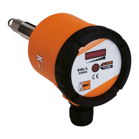
Kobold KAL-L User manual

Operating Instruction
for
Calorimetric flow switch for air
Model: KAL-L

KAL-L
page 2 KAL-L K03/0422
1. Contents
1.Contents ........................................................................................................ 2
2.Note .............................................................................................................. 3
3.Regulated usage ........................................................................................... 3
4.Operating Principle ........................................................................................ 4
5.Instrument Inspection .................................................................................... 4
6.Mechanical connection .................................................................................. 5
7.Electrical connection ..................................................................................... 5
8.Operation ...................................................................................................... 6
9.Commissioning.............................................................................................. 7
10.Technical Data .............................................................................................. 8
11.Maintenance ................................................................................................. 8
12.Order codes .................................................................................................. 9
13.Recommended spare parts ........................................................................... 9
14.Dimensions ................................................................................................. 10
15.EU Declaration of Conformance ................................................................. 11
Manufactured and sold by:
Kobold Messring GmbH
Nordring 22-24
D-65719 Hofheim
Tel.: +49(0)6192-2990
Fax: +49(0)6192-23398
E-Mail: [email protected]
Internet: www.kobold.com

KAL-L
KAL-L K03/0422 page 3
2. Note
Please read and take note of these operating instructions before unpacking and
setting the unit for operation, and follow the instructions precisely as described
herein.
The instruction manuals on our website www.kobold.com are always for currently
manufactured version of our products. Due to technical changes, the instruction
manuals available online may not always correspond to the product version you
have purchased. If you need an instruction manual that corresponds to the
purchased product version, you can request it from us free of charge by email
([email protected]) in PDF format, specifying the relevant invoice number and
serial number. If you wish, the operating instructions can also be sent to you by
post in paper form against an applicable postage fee.
The devices are only to be used, maintained and serviced by persons familiar
with these operating instructions and with the prevailing regulation applying to
procedural safety and the prevention of accidents.
When used in machines, the measuring unit should be used only when the
machines fulfil the EC-machine guidelines.
3. Regulated usage
The KAL-L is to be installed only in the specified applications. Every usage which
exceeds the specifications is considered to be non-specified. Any damages
resulting therefrom are not the responsibility of the manufacturer. The user
assumes all risk for such usage. The application specifications include the
installation, start-up and service requirements specified by the manufacturer.
The devices from the KAL-L model series are used for the monitoring of air flow.
The devices can be used from a pipe size of 20 mm upwards.
Flow range: 1 m/s ... 20 m/s (at 20 °C, 1 bar rel)
Please note that the flow range is reduced if any
other operating pressure or temperature applies.
Temperature range: -25 °C ... +120 °C
max. pressure: 8 bar
Limiting signal
For monitoring the velocity of air these devices with terminal connection are
equipped with a potential free change over contact; devices with plug-connection
are with N/O or N/C contact.
Trend indication
A LED bar graph display shows the current flow value and the set switch point via
a flashing LED.

KAL-L
page 4 KAL-L K03/0422
Duo-LED
displays the actual status of the relay.
Material
Sensor: Brass nickel plated
Electronic housing: Glass fibre reinforced Polyamid.
The devices of the series KAL-L are used for monitoring air flow only.
4. Operating Principle
The operation of the electronic flow monitor KAL-L... is based on the proven
calorimetric principle. A sensor is heated to a few degrees above the temperature
of the flow medium. When the medium flows, the heat generated in the sensor is
transferred to the medium, i.e., the sensor is cooled. This cooling process is a
measure of the flow velocity. A second sensor measures the medium
temperature. The electronics compares the resistances of both sensors by means
of a Wheatstone bridge circuit, and switches an output relay if the actual value
drops below the set switching value.
5. Instrument Inspection
These devices are checked before dispatch and sent away in perfect condition.
Should the damage to a device be visible, we recommend a thorough inspection
of the delivery packing. In case of damage, please inform your parcel service/
forwarding agent immediately, since they are responsible for damages during
transit.
Scope of delivery:
The standard delivery includes:
Electronic Flow Monitor for Air model: Kal-L

KAL-L
KAL-L K03/0422 page 5
6. Mechanical connection
Before installation
Ensure that the actual system velocity is within the switching range of the device.
Ensure that the permitted maximum operating pressure and temperature for the
device is not being exceeded. (See section 10. Technical data).
Installation
Mount the sensor by using the compression fitting or the flange into the
corresponding pipe and ensure that the sensing elements are in contact with the
flowing medium. The tip of the probe has to project into the pipe minimum 10 mm
(better > 15 mm) (see sketch below).
Optimally the probe is that far inserted that the sensing elements is located
approx. in the centre of the pipe. For pipe sizes larger than 50 mm the sensor
shall be mounted as far as possible into the pipe.
Fitting position
The function of the sensor is not dependent on
their fitting position. Please note that the
marking (1), which is on the hexagon of the
sensor, is absolutely parallel to the flow
direction. To avoid incorrect function of the
sensor the straight pipe upstream should be 10
times ID and downstream 5 times ID.
7. Electrical connection
Terminal connection
Unscrew the cover of the electronics.
Connect the device according to the
information at the terminal ports.
When DC voltage is used no polarity is to be
watched.
Warning: Ensure that the power is disconnected during the connection of
the cable.
Put supply voltage to the device (24 VAC/DC, -15%, +10%)
Plug connection (Plug M12 x 1)
PIN 1 brown 24 VAC/DC
PIN 2 white 24 VAC/DC
PIN 3 blue relais N/O or N/C
PIN 4 black relais N/O or N/C

KAL-L
page 6 KAL-L K03/0422
8. Operation
LED-trend indication
The LED-trend indication (8 LED) is used to display
the actual flow value (LED-chain starts to light from
left end)
flow too low O O O O O
flow is OK O O O
the set point
(third LED from left flashing)
set point O O O O O O O
Duo-LED
The Duo-LED is used to display
the status of the relay
red = Alarm (set point not reached; relay is deactivated)
green = Flow (set point exceeded; relay is activated)
Terminal ports
The terminal ports are used to connect the power supply and the relay output.
The device needs 24 VDC/VAC. No polarity is to be watched.
Potentiometer (range amplification)
The switch point is always set on the third LED from left. With the left
potentiometer, the amplification of the range and the maximum position of flow
value are set on the LED bar display. Depending on the distance of maximum
value LED from switch point LED, small or large flow variations are permitted.
Potentiometer for time delay after start up
With the right potentiometer the time delay (1 to 60 seconds) can be adjusted. If
the power supply is switched on the relay is activated until the delay time is
passed. The flow switch indicates "FLOW". After the time delay passed the
device switches into measuring mode.

KAL-L
KAL-L K03/0422 page 7
9. Commissioning
The use of this switch in machines acc. to directive 2006/42/EC is prohibited until
the complete machine complies with this directive.
After mechanical and electrical installation of the sensor the device has to be put
into operation as described in this section.
Switch on the supply voltage to the device.
Adjustment of the time delay after start up
If the power supply is switched on the relay is activated until the delay time is
passed. The flow switch indicates "FLOW" even if the flow rate is lower.
The time delay can be adjusted in a range of 1 to 60 seconds. After the time
delay passed the device switches into measuring mode.
Turning the potentiometer clockwise increases the time delay.
Set point adjustment
The set point is factory preset. It is indicated by the third LED from left hand side
flashing. The adjustment of the set point is done by an adjustment of the
amplification of the range.
Regulate the flow to the required flow rate.
Max. monitoring: Adjust the amplification with the left potentiometer until one
or two LEDs left from the set point (third LED) are lit.
1 LED left of set point LED OO O O O O
--> setpoint close above actual flow rate, rela
y
deactivated
Min. monitoring: Adjust the amplification with the left potentiometer until some
LEDs right from the set point (third LED) are lit.
1 LED right of set point LED O O O O
--> setpoint close below actual flow rate, rela
y
activated
5 LED`s right of set point LED
--> set point far below actual flow rate, rela
y
activated
After mounting of the cover the flow switch is ready for use.

KAL-L
page 8 KAL-L K03/0422
10. Technical Data
Power supply: 24 VAC/DC - 15%, +10%
Power consumption: max. 4 VA
Ambient temperature: -10 °C...+60 °C
Temperature of medium: -25 °C...+120 °C
Max. pressure: 8 bar
Warm-up time: max. 30 s
Switching range: 1…20 m/s (at 20 °C, 1 bar)
(restricted span for other pressure and
temperature conditions)
Switching accuracy: ± 10% of reading
Repeatability: ± 1% of reading
Temperature gradient: 30 K/min. (at 8 m/s, 90 °C)
Response time: 1...60 s adjustable
Flow rate indication: 8-digit LED bargraph
Switch point adjustment: with potentiometer
Output indicator: two-colour LED
Switch-output: relay, floating changeover contact
Switch capacity: max. 250 VAC/1000 VA/4 A
Except for KAL-…ST:
max. 24 VAC/DC/3 A
Protection: IP 65
Case material: glass fibre reinforced polyamide
Sensor material: brass, nickel plated
11. Maintenance
The device is maintenance free. The sensor shall be visually checked and
possibly cleaned with air.

KAL-L
KAL-L K03/0422 page 9
12. Order codes
Example: KAL-L81FL WK ST
Connection Order No. Electr. connection/
cable connector
Smooth shaft
D = 15 mm KAL-L8100 WK PG = cable connection
M16x1.5
ST = connector M12x1
S4 = connector DIN 43650
N4 = ½” NPT for cable
connection
Compression fitting
G ½ KAL-L81G1 WK
Compression fitting
Rp ½ KAL-L81R1 WK
Compression fitting
½” NPT KAL-L81N1 WK
with clamping flange
acc. to DIN 43 743 KAL-L81FL WK
M18x1.5 KAL-L0118 W
K
13. Recommended spare parts
We do not recommend any spare parts. In case of defect the device has to be
returned to the supplier.

KAL-L
page 10 KAL-L K03/0422
14. Dimensions
KAL-L8100 WK
KAL-L0118 WK

KAL-L
KAL-L K03/0422 page 11
15. EU Declaration of Conformance
We, KOBOLD-Messring GmbH, Hofheim-Ts, Germany, declare under our sole
responsibility that the product:
Electronic Flow Monitor Model: KAL-L
to which this declaration relates is in conformity with the standards noted below:
EN 61000-6-2:2011
Electromagnetic compatibility (EMC) - Part 6-2: Generic standards - Immunity for
industrial environments
EN 61000-6-3:2011
Electromagnetic compatibility (EMC) - Part 6-3: Generic standards - Emission
standard for residential, commercial and light-industrial environments
EN 55011:2011
Industrial, scientific and medical equipment - Radio-frequency disturbance
characteristics - Limits and methods of measurement
EN 61010-1:2010
Safety requirements for electrical equipment for measurement, control and
laboratory use - Part 1: General requirements
EN 50581:2012
Technical documentation for the assessment of electrical and electronic products
with respect to the restriction of hazardous substances
Also, the following EC guidelines are fulfilled:
2014/35/EU Low Voltage Directive
2014/30/EU EMC Directive
2011/65/EU RoHS (category 9)
Hofheim, 04 Febr. 2019
H. Peters M. Wenzel
General Manager Proxy Holder
Table of contents
Other Kobold Switch manuals

Kobold
Kobold NCG NCM Series User manual

Kobold
Kobold BVO Series User manual

Kobold
Kobold TDD User manual

Kobold
Kobold NE-104 User manual

Kobold
Kobold NAB User manual

Kobold
Kobold PSR series User manual

Kobold
Kobold NSV Series User manual

Kobold
Kobold AFS-G3 User manual
Kobold
Kobold NBK-RV200NO User manual

Kobold
Kobold M Series User manual