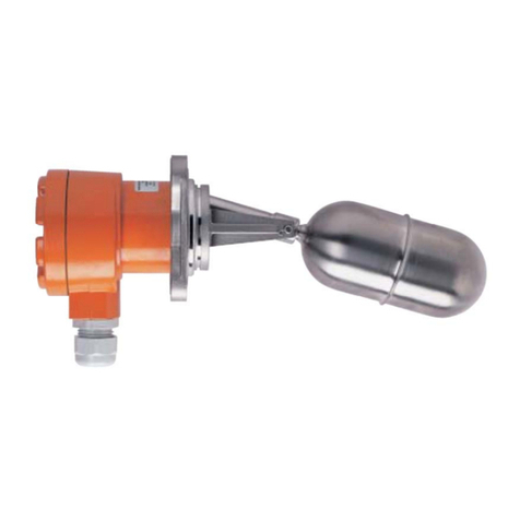
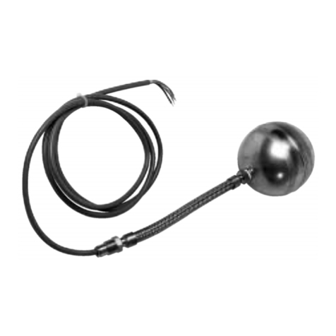
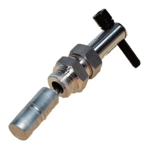
Kobold NCG NCM Series User manual

Page 1 | 14
Operation Instructions Rev.7 Nov. 2022
Specifications are subject to change.
Operating
Data
Installation
Maintenance
Instructions
For
Multi-Level Switch
NCG NCM SERIES
KOBOLD Instruments Inc
1801 Parkway View Drive
Pittsburgh PA 15205-1422
Tel.: 412-788-2830
Fax: 412-788-4890
E-Mail: [email protected]
Internet: www.koboldusa.com

SR & SSR SERIES SWITCHES
Page 2 | 14
Operation Instructions Rev.7 Nov. 2022
Specifications are subject to change.
1. Note
*****Please read and take note of these operating instructions before commissioning.
The instruments may only be used, maintained, and installed by qualified personal familiar
with the operating instructions and the applicable health and safety requirements. *****
2. Contents
1. Note
2. Contents
3. Specific Applications
4. Operating Principle
5. Instrument Instructions
6. Technical Specifications
7. Mechanical Connections
8. Electrical Connections
9. Adjustments
10. Switch Protection
11. Troubleshooting
12. Maintenance
13. Warranty
3. Specific Applications
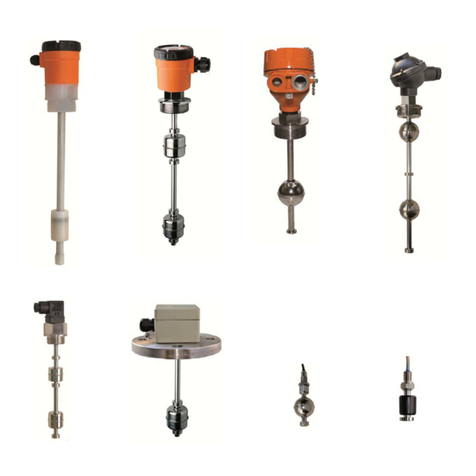
The Level Control Gauge has been designed for use in level monitoring applications and pump
control for liquids
The probe part of the gauge can be manufactured from most non-magnetic materials including
plastics. The floats can be either stainless, buna or engineered plastic.
The Multi-Level sensor can be configured from the factory with one to seven switch points set to
customer specific locations and switch state.
4. Operating Principles
Hermitically sealed reed switches are potted inside the tube on a continuous wire harness. Other
models may use a printed circuit board design. The float (stainless, buna or plastic all contain
either a rod or ring magnet potted or gripped inside. As fluid moves the float – its magnetic lines
of force meet the reed switch – and activate it to either an open or closed state.
N/C – With liquid present – the switch point will be open – contacts not conducting. The contacts
will close as the float descends
N/O – With liquid present – the switch point will be closed – contacts will open as the float
descends
5. Instrument Instructions
The instruments are thoroughly tested and inspected by the factory prior to shipment and sent in
perfect working condition. Should any damage to the device be visible, we recommend a
thorough inspection of the delivery packaging. In case of damage please inform your
parcel service/forwarding agent immediately, since they are responsible for damages
incurred during transit.
⚠CAUTION! This unit contains reed switches that may be permanently damaged by
mechanical shock or vibration. Avoid dropping or hitting the device against hard
surfaces.

SR & SSR SERIES SWITCHES
Page 3 | 14
Operation Instructions Rev.7 Nov. 2022
Specifications are subject to change.
⚠CAUTION! If the equipment is used in a manner not specified by the manufacturer,
protection provided by the equipment may be impaired.
⚠CAUTION! Ensure that the wetted components of the transducer are compatible with
the media being measured.
6. Technical Specifications
Technical Data Sheet
Instrument Type
Multi - Level Switch SR & SSR series
Operating Temperature
Flying leads: -40° ~ 80°C, (Cable: -40°~70°)
Storage Temperature
-50°C ~ 80°C
Max Pressure
80 PSIG
SPST Reed Switch, 70 W max
200 VDC / 150 VAC @0.5A
SPDT Reed Switch, 20 W max (optional)
150 VDC / VAC @ 0.5A
High Temperature ‘HT’ (optional)
-40°C ~ 120°C
SSR SERIES FLOAT SIZE
SPECIFIC
GRAVITY
STAINLESS STEEL 22mm X 40mm
0.93
STAINLESS STEEL 28mm X 28mm
0.66
STAINLESS STEEL 38mm X 26mm
0.56
POLYPROPYLENE FOAM 25mm X 25mm
0.7
CLOSED CELL BUNA 26mm X 25mm
0.7
CLOSED CELL BUNA 25mm X 15mm
0.5
CLOSED CELL BUNA 18mm X 26mm
0.7
SR SERIES FLOAT SIZE
SPECIFIC
GRAVITY
STAINLESS STEEL 50mm BALL
0.65
STAINLESS STEEL 40mm X 35mm
0.68
STAINLESS STEEL 46mm X 76mm
(DIFFERENTIAL FLOAT)
0.96
POLYPROPYLENE HOLLOW 47mm X 48mm
0.5
CLOSED CELL BUNA 47mm X 47mm
0.42
CLOSED CELL BUNA 40mm X 45mm
0.4
CLOSED CELL BUNA 30mm X 45mm
0.4
7. Mechanical Connections
Use caution when handling the wires, as they can be easily crushed against the head or potting.
Ensure that the bottom of the probe does not come in contact with the tank bottom, as the probe
will easily bend.
Use a wrench on the larger of the two fittings to install. Do not use any tool or clamp on the
actual probe tube.
Special precautions should be taken if installed in a dirty environment with debris in the tank.
8. Electrical Connection
⚠CAUTION: Ensure that the voltage levels of your power supply system
agree with the voltage levels given on specification sheet.
The transducer is a pilot duty device, good for millions of operations if
installed correctly.

SR & SSR SERIES SWITCHES
Page 4 | 14
Operation Instructions Rev.7 Nov. 2022
Specifications are subject to change.
⚠CAUTION: Make sure all power supplies to equipment are disconnected
and locked out prior to installation or maintenance.
The device must be installed to local electrical codes.
•Improper wiring can lead to damage to this device as well as injury to the user.
•Make sure that installation, wiring and circuit protection are in accordance with all local
electrical codes.
•Make sure the supply circuit provides adequate fuse or circuit breaker protection that
is in accordance with the circuit’s current rating.
•If supplied withoptional connection head. Strip field wiring to 8mm max and make
connection to proper terminal block, using color code below wiring table.
•Field wiring must be rated to 80°C for standard units, 125°C for high temp units.
Wiring Table
SPST 70 WATT
Level 1 – RED
Level 2 – YEL
Level 3 – BLU
Level 4 – BRN
Level 5 – ORG
Level 6 - GR
SPDT 20 WATT Common N/O N/C
Level 1 RED WHITE / RED WHITE / BLACK / RED
Level 2 YELLOW WHITE / YELLOW WHITE / BLACK / YELOW
Level 3 BLUE BLACK ORANGE
The reeds are factory set in the dry position. Be sure to connect the wires and check using an
OHM meter only per reed switch specifications.
9. Adjustments
Multilevel controls are not adjustable.
In some cases, the float can be adjusted to the opposite state by moving the collars and setting
the float using an ohmmeter.

SR & SSR SERIES SWITCHES
Page 5 | 14
Operation Instructions Rev.7 Nov. 2022
Specifications are subject to change.
10.Switch Protection
⚠CAUTION IF THE FOLLOWING INSTRUCTIONS ARE NOT FOLLOWED,
THE REED SWITCHES IN THIS DEVICE WILL FAIL!
This device incorporates reed switches which are used for sensing purposes and can only switch very small loads (pilot
duty service). They are not designed to directly switch solenoid valves, motors, and other high current devices.
When testing reed switches for operation only use an Ohmmeter and not a light.
The common accepted practice is to use an interface relay rated to handle the required electrical load. In this way, the low
current signal from the reed switch energizes the relay coil, which in turn switches the larger load current.
PLEASE READ CAREFULLY!!
How to avoid damaging the reed switch:
TO PROTECT THE REED SWITCH AGAINST INDUCTIVE KICKBACK, EVEN IF THE RELAY COIL CURRENT
RATING IS WELL BELOW THE REED SWITCH RATING:
When a reed switch is used to drive external relays, voltage spikes can be generated at coil activation.
If the source is an AC operated device, install a varistor (MOV), or Resistor/Capacitor Filter across the relay coil.
If the source is a DC operated device, a general-purpose diode (IN 4004) placed across the relay coil prevents
electrical spikes. Connect the cathode (banded side) to the more positive side of the coil.
The reeds are factory set in the dry position. Be sure to connect the wires and check using an OHM meter only
per reed switch specifications. All level controls are sold with a NEMA 4 Junction Box option to protect the
potted wire exit from unit. If you did not opt for this option…. then water exposed to this area can wick into the
unit causing a “closed” condition.
Diode
1N4004
Relay
Coil
+VDC
-VDC
Reed Switch
Pilot Duty
DC Circuit Example
Relay
Contact To
Load
MOV or
RC Filter
Relay
Coil
110 VAC
(Line)
Neutral
Reed Switch
Pilot Duty
AC Circuit Example
Relay
Contact To
Load
MOV Type: GE # V130 LA10
RC Filter Type: Paktron # 0.2uF/220 Ohm @400 V

SR & SSR SERIES SWITCHES
Page 6 | 14
Operation Instructions Rev.7 Nov. 2022
Specifications are subject to change.
11.Troubleshooting
PROBLEM
CAUSE
SOLUTION
The unit is unresponsive.
Electrical failure.
Use an electrical continuity checker to
determine if the switch is functional. If the
switch does not operate properly when
activated by a magnet, the entire level
switch must be replaced.
The unit does not activate when the float
changes position.
The unit is jammed.
Remove the level switch from service.
Check the float assembly for obstructions
or accumulation of particles which may
cause binding. If binding is present in the
float assembly and cannot be cleared by
normal cleaning procedures, the entire
control must be replaced.
The float is not buoyant.
The float is collapsed and/or filled with
liquid or the correct float was not selected
at time of order.
Check the float for ruptures, deformation,
and any liquid trapped inside the
assembly. If the float is filled with liquid or
has collapsed, the entire level switch must
be replaced. Do not attempt to repair the
float.
12. Maintenance
Preventative Maintenance should be done monthly.Depending on the environment inside the
tank, this may need to be more often.
•Disconnect all power to device
•Clean and visually inspect stem, float and stops and electrical connection for any
damage.
•If damaged, the unit will need to be replaced, do not put back inservice.
There are no user serviceable parts inside the Level Transducer. If repair is required, please
contact your local distributor to return it for repair.
13. Warranty
All Almeg Controls level controls are warranted free of defects in materials and workmanship for one full year from the date of the original factory shipment.
If returned within the warranty period; and, upon factory inspection of the control, the cause of the claim is determined to be covered under the warranty;
then, Almeg Controls will repair or replace the product at no cost to the purchaser (or owner) other than transportation. Almeg Controls shall not be liable for
misapplication, labor claims, direct or consequential damage, or expenses arising from the installation or use of the equipment. There are no other warranties
expressed or implied, except special written warranties covering specific Almeg Controls products.

KOBOLD Series NCG/NCM Multipoint Level Switches
Wiring Diagram
SPST Switch Wiring Standard Wire
L6 Gray Gray
L5 Orange Orange
L4 Brown Brown
L3 Blue Blue
L2 Yellow Yellow
L1 Red Red
SPDT Switch Wiring
L4 Brown
L3 Blue
L2 Yellow
L1 Red
White
Gray
Black
Orange
Wh/Yellow
Wh/Blk/Yellow
Wh/Red
Wh/Blk/Red
NCM
NCG
A = 1 1/2" min distance to highest level
B = 3" min distance between levels
C = 2" min distance from end of unit to lowest
level
MAX SWITCH POINTS:
NCG = 6 SPST / 4 SPDT
NCM = 4 SPST / 2 SPDT
SPST Switch Wiring with PTFE Wire
L3 Blue Blue
L2 Yellow Yellow
L1 Red Red
L3 White White
L2 Black Black
L1 Red Red
Other Kobold Switch manuals

Kobold
Kobold NAB User manual

Kobold
Kobold LNK User manual

Kobold
Kobold NBK-RA User manual

Kobold
Kobold SCH User manual

Kobold
Kobold NV User manual

Kobold
Kobold TWR User manual

Kobold
Kobold NBK-R series User manual

Kobold
Kobold NSP User manual

Kobold
Kobold NBK-RV200NO User manual

Kobold
Kobold PPS-1201 User manual

Kobold
Kobold NWS-5225 Installation instructions
Kobold
Kobold NEK Series User manual

Kobold
Kobold RFS User manual

Kobold
Kobold NSV Series User manual

Kobold
Kobold NSM User manual

Kobold
Kobold NAS User manual

Kobold
Kobold TDD-153 series User manual

Kobold
Kobold LNZ User manual
Kobold
Kobold NSM User manual

Kobold
Kobold NIR-9 User manual