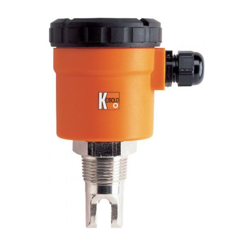
Kobold NSV Series User manual

Operating instructions
For
Vibration level switch
Model NSV

NSV
Page 2 DT0335
1. Content
1.Content .........................................................................................................2
2.Note ..............................................................................................................3
3.Instrument Inspection....................................................................................3
4.Regulation use ..............................................................................................3
5.Operating Principle........................................................................................4
6.Mechanical Connection.................................................................................5
7.Electrical connection .....................................................................................7
8.Commissioning..............................................................................................7
9.Maintenance .................................................................................................8
10.Technical information ....................................................................................9
11.Order Codes ...............................................................................................10
12.Dimensions, standard models.....................................................................10
13.Safety Instructions (ATEX)..........................................................................11
14.Installation in classified zone (ATEX) ..........................................................12
15.Label Description (ATEX)............................................................................13
16.Dimensions, ATEX models .........................................................................13
17.Declaration of conformance (ATEX)............................................................14
18.Declaration of conformance ........................................................................15
19.ATEX Certificate..........................................................................................16
20.Notes...........................................................................................................19
Manufactured by:
Kobold Mesura S.L.U
Avda. Conflent 68, nave 15
08915 Badalona
Tel.: +34 93 460 38 83
Fax: +34 93 460 38 76
Internet: www.kobold.com
june 2017

NSV
DT0335 Page 3
2. Note
Please read these operating instructions before unpacking and putting the unit
into operation. Follow the instructions precisely as described herein.
The devices are only to be used, maintained and serviced by persons familiar
with these operating instructions and in accordance with local regulations
applying to Health & Safety and prevention of accidents.
When used in machines, the measuring unit should be used only when the
machines fulfil the EC-machine guidelines.
3. Instrument Inspection
Instruments are inspected before shipping and sent out in perfect condition.
Should damage to a device be visible, we recommend a thorough inspection of
the delivery packaging. In case of damage, please inform your parcel service /
forwarding agent immediately, since they are responsible for damages during
transit.
Scope of delivery:
The standard delivery includes:
- Level Monitor for Bulk model: NSV
- Operating instructions
4. Regulation use
The Level Monitor is designed for the selective level monitoring of bulk materials,
especially for bulk material with low bulk density. This level monitor is not
sensitive to material dampness and can be employed regardless of the
composition of the bulk material.
Any use of the Level Monitor for Bulk, model: NSV, which exceeds the
manufacturer’s specification may invalidate its warranty. Therefore, any resulting
damage is not the responsibility of the manufacturer. The user assumes all risk
for such usage.

NSV
Page 4 DT0335
5. Operating Principle
The Level Monitor model NSV has decisive advantages, especially with bulk
goods with low bulk density.
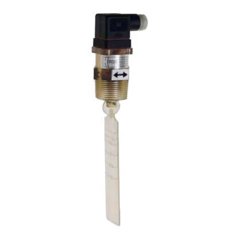
The sensor consists of a connecting head, which contains the electronics, and an
adaptor with an oscillating fork. The latter is responsible for the direct contact with
the bulk material. Two piezoelectric crystals start the fork vibrating at about 100
Hz. As soon as the fork is covered with the bulk material its vibration is
dampened. This damping is detected in a pluggable evaluation module and
transformed into a potential-free limit contact. With the aid of a selector switch (A
and B) the relay can be switched on or off with every contact of the fork with the
bulk material. At the same time, the electronics in the connecting head triggers
the output relay. The electronics in the connecting head consists of a
maintenance-friendly plug-in module that is fitted with an LED voltage supply
indicator and an additional LED that lights up whenever the fork touches the
medium.
In addition to the standard version NSV-8200, the devices can also be provided
for vertical installation with an extended neck pipe (NSV-8201). The maximum
length of the neck pipe is 3000 mm. The plug-in evaluation module can be
changed easily so that the devices are really easy to maintain.

NSV
DT0335 Page 5
6. Mechanical Connection
Before installation:
Remove all packing materials and transport retainers and ensure that no
such materials remain in the device.
Make sure that the permitted max. operational pressure and temperature
limits are not exceeded (see chapter 10 Technical Information)
The units may not be installed at a location within an inductive field.
If possible, check directly after mechanical installation whether the
connection thread to the pipe is fully sealed.
INSTALLATION OF THE NSV VIBRATION LEVEL MONITOR
The NSV series vibration level monitor is physically connected with a 1 ½” male
thread. For installation you should use the hexagonal adaptor (60 mm spacing) of
a suitable wrench.
THE FOLLOWING MUST BE OBSERVED UNDER ALL CIRCUMSTANCES:
When the bulk material container is being filled, the NSV level monitor
must not come into contact with the inflowing medium.
If this is however not possible, the vibrating fork must be fitted with a
suitable protective covering.
Make sure that the fork is always positioned correctly inside the bulk
container and that no bulk material deposit is formed on it, since this can
result in incorrect readings. If the NSV level monitor is built in laterally you
must ensure that the markings on the adaptor are vertical in relation to the
side of the container.
When the NSV vibration level monitor is installed vertically a minimum
distance must be maintained between the fork and the container wall
otherwise this area could be filled with a deposit of the bulk material.
Whenever possible the NSV level monitor should be fitted with a slight
downward inclination. This prevents bulk material sticking to the vibrating
fork when the container is being emptied.
The level monitor should also be installed in such a position that there are
no parts in its immediate vicinity that could trigger vibrations in the inside of
the container, since this can also lead to incorrect readings or damage.
For correct positioning the connection head (resp. cable bushing) is 350º
rotatable.

NSV
Page 6 DT0335

NSV
DT0335 Page 7
7. Electrical connection
The voltage supply to the NSV level monitor is via the connecting terminals L1 (+)
and N(-) Suitable safety fuses are to be built in to the electric input lead. The
green LED indicates that there is power to the device. Before connecting the
device check that the supply voltage matches the characteristics of the NSV level
monitor.
8. Commissioning
RELAY OPERATION
When the red LED lights up, this indicates contact between vibrating fork and
medium. Ensure that the red LED works independently of the position of the
SELECTION SWITCH. As long as the fork vibrates, the red LED will not light up.
As soon as the vibrating fork comes into contact with the bulk material the red
LED indicator will light up.
SELECTION SWITCH (A or B)
The on and off state of the output relay depends on the position of the
SELECTION SWITCH.
POSITION A: The relay remains switched off as long as the medium does NOT
touch the vibrating fork.
POSITION B: The relay remains switched on as long as the medium does NOT
touch the vibrating fork.

NSV
Page 8 DT0335
9. Maintenance
The Level Monitor has to be controlled regularly for deposits of bulk material in
the area of the vibration fork. Therefore we recommend a periodic cleaning. The
connection housing should be checked periodically for mechanical damages to
guarantee the indicated protection class.

NSV
DT0335 Page 9
10. Technical information
Note: Kobold Mesura makes every attempt to ensure the accuracy of these
specifications but reserves the right to change them at any time.
Measuring principle: vibration
Max. length
of immersion length: 3000 mm
Medium temperature: -20 to +80 °C
Ambient temperature: -20 to +60 °C
Minimum density of bulk: 60 g/L
Fork material: stainless steel (1.4305)
Housing material: Polycarbonate, 350° turnable
Mechanical connection: G 1 1/2, stainless steel (1.4305)
Electrical connection: via 1 (2) cable gland M20x1.5
Supply voltage: 24, 110, 230 VAC
50/60 Hz or 18...36 VDC
Maximum power input: 1 VA
Relay output: max. 250 VAC, 1 A
Max. pressure ( at 20 ºC ): 25 bar
Protection: IP 65
ATEX marking: II 1/2 D Ex tD A20/21 IP 65 T85°C
-20 °C ≤Ta ≤+60 °C

NSV
Page 10 DT0335
11. Order Codes
Order Details (Example: NSV-8 2 00 G8 0 0)
Model Version Material Immersion
length
Mechanical
connection ATEX Supply voltage
NSV-8 = standard
2=
stainless
steel 1.4305
00 = standard,
short version
01 = extended
version (max
3m)
G8 = G1 ½
0 = without
E = ATEX
0= 230VAC
2= 24VAC
3= 18…36 VDC
4= 100VAC
12. Dimensions, standard models
NSV-8200G800 NSV-8201G800

NSV
DT0335 Page 11
13. Safety Instructions (ATEX)
1. Validity
This safety instructions must be applied to the ATEX-conform vibration level
switch series NSV….E, used in dust explosion hazard environments, category 1/2
D.
2. General considerations.
Working principle of level switches NSV...E is vibrating fork, generated with a
piezo electric oscillator fixed to a tuning fork. Detection is done with a piezo
electric sensor that is measuring the amplitude difference when fork is in contact
or not with the product. It can be used also in hazardous zones.
They are designed to be used in explosion-proof areas classified as group II,
category 1/2D.
Sensor element can be installed in hazardous areas category 1 under ATEX
approval 1/2D Ex tD.
The mechanical side of the instrument (thread connection and tuning fork) can be
installed in hazardous areas category 2, as mentioned in ATEX approval 1/2D Ex
tD.
When installing the device it is necessary to follow all instructions and regulations
for explosion-proof areas and the safety instructions included in this manual.
Inlet bushings and electrical connections must conform to the certification for their
type in accordance with the directive.
Verify that label contents fits requirements of application.
All requirements of the 2014/34/EU Directive must be correctly followed and also
the national rules related to measurement instruments used in hazardous areas.
For instance: EN 60079-0, EN 60079-31 and all the other ones related to the
required certification.
Remove power supply before opening cover of the housing or at least be sure
that no explosion risk is present.
Check that cover of housing is correctly mounted before applying power to the
instrument.
Verify that there is no mechanical stress due to installation on the tank.
It is very important to verify that the instrument ground and the system ground are
correctly connected.
The installation of instruments in hazardous areas must be exclusively done by
trained people.

NSV
Page 12 DT0335
3. Protection against electrostatic discharge
Level switches with plastic parts that can acquire electrostatic charges, must
have a corresponding warning label.
Avoid situations of electrostatic discharges like:
-Avoid friction on plastic parts.
-Avoid cleaning with a dry cloth
-Avoid installing close the steam sources or pneumatic product sources.
4.Chemical resistance:
Verify that materials of the instrument are chemically compatible with the product
to measure and application.
14. Installation in classified zone (ATEX)
In classified zones, NSV. ATEX version, must be installed with the housing in
zone 21,22 (category 2) or NOT CLASSIFIED.
Process connection is mounted in the border wall between areas of category 2
and 1.
fork can be mounted in ZONE20 (Category 1).
Installation must be done by people trained in ATEX environments.

NSV
DT0335 Page 13
15. Label Description (ATEX)
16. Dimensions, ATEX models
NSV-8200G8E0 NSV-8201G8E0

NSV
Page 14 DT0335
17. Declaration of conformance (ATEX)
DT0323
DECLARACIÓN DE CONFORMIDAD EU
EU DECLARATION OF CONFORMITY
EU-KONFORMITÄTSERKLÄRUNG
DÉCLARATION DE CONFORMITÉ
DICHIARAZIONE DI CONFORMITÀ EU
KOBOLD MESURA S.L.U.
Avda. Conflent 68 nave 15, 08915 Badalona (España)
Declara, bajo la propia responsabilidad, que el producto
Declares under our sole responsibility, that the product
Erklärt in alleiniger Verantwortung, dass das Produkt
Déclare sous sa seule responsabilité, que le produit
Dichiara sotto la propia responsabilità, che il prodotto
SOLIVIB....E.. / NSV....E..
A los cuales se refiere esta declaración, son conformes a las siguiente Directivas Europeas:
To which this declaration relates is in conformity with the following European Directives:
Mit folgenden Richtlinien konform ist:
À auxquels se réfère cette déclaration, ils sont conformes aux Directives Européennes suivant :
A ai quali si riferisce questa dichiarazione, sono conformi alle direttive europee seguente:
EMC2014/30/EU LVD2014/35/EU ATEX2014/34/EU RoHS2011/65/EU
Normas armonizadas y documentos de la normativa aplicados:
Applied harmonised standards and normative documents:
Angewandte harmonisierte Normen oder normative Dokumente:
Normes harmonisées et documents normatifs appliqués
Norme armonizzate e documenti normativi applicati:
EN61010-1 :2011 EN61241-1:2004 (acc. EN60079-31 :2016)
EN61000-6-1 :2007 EN61241-0:2006 (acc. EN60079-0 :2013)
EN61000-6-3:2007
Certificado de examen CE de tipo Marcado
EC-type examination certificat Marking
EG-Baumusterprübescheinigung Markierung
Attestation d´examen CE de type Inscription
Certificazione per esame di tipo CE Marcatura
LOM 08ATEX2039
II 1/2D Ex tD A20/A21 IP65 T80ºC
-20ºC≤Ta ≤60ºC
Fabricado en: KOBOLD MESURA SLU Avda. Conflent 68 nave 15, 08915 BADALONA (Spain)
Made in:
Hergesteltlt in:
Fabriqué dans:
Fabbricato in:
Organismo notificado: Número notificación :
LOM 0163 LOM 05ATEX9070
Notified organism Number notification
Zertifizierungsstelle Zertifikatsnummer
Organization annoncée Nombre notification
Organismo informato Notifica di numero
Badalona june 2017 Gerente
Azzam Charmand

NSV
DT0335 Page 15
18. Declaration of conformance
DT0323
DECLARACIÓN DE CONFORMIDAD EU
EU DECLARATION OF CONFORMITY
EU-KONFORMITÄTSERKLÄRUNG
DÉCLARATION DE CONFORMITÉ
DICHIARAZIONE DI CONFORMITÀ EU
KOBOLD MESURA S.L.U.
Avda. Conflent 68 nave 15, 08915 Badalona (España)
Declara, bajo la propia responsabilidad, que el producto
Declares under our sole responsibility, that the product
Erklärt in alleiniger Verantwortung, dass das Produkt
Déclare sous sa seule responsabilité, que le produit
Dichiara sotto la propia responsabilità, che il prodotto
SOLIVIB...... / NSV....
A los cuales se refiere esta declaración, son conformes a las siguiente Directivas Europeas:
To which this declaration relates is in conformity with the following European Directives:
Mit folgenden Richtlinien konform ist:
À auxquels se réfère cette déclaration, ils sont conformes aux Directives Européennes suivant :
A ai quali si riferisce questa dichiarazione, sono conformi alle direttive europee seguente:
EMC2014/30/EU LVD2014/35/EU RoHS2011/65/EU
Normas armonizadas y documentos de la normativa aplicados:
Applied harmonised standards and normative documents:
Angewandte harmonisierte Normen oder normative Dokumente:
Normes harmonisées et documents normatifs appliqués
Norme armonizzate e documenti normativi applicati:
EN61010-1 :2011
EN61000-6-1:2007
EN61000-6-3:2007
Fabricado en: KOBOLD MESURA SLU Avda. Conflent 68 nave 15, 08915 BADALONA (Spain)
Made in:
Hergesteltlt in:
Fabriqué dans:
Fabbricato in:
Badalona june 2017 Gerente
Azzam Charmand

NSV
Page 16 DT0335
19. ATEX Certificate

NSV
DT0335 Page 17

NSV
Page 18 DT0335

NSV
DT0335 Page 19
20. Notes

NSV
Page 20 DT0335
KOBOLD MESURA S.L.U
Avda. Conflent 68, nave 15
08915 Badalona
Tel.: +34 93 460 38 83
Fax: +34 93 460 38 76
E-Mail: [email protected]
www.kobold.com
Technical data
Subject to change without prior notice
.
This manual suits for next models
2
Table of contents
Other Kobold Switch manuals

Kobold
Kobold NSM User manual

Kobold
Kobold TDD Series User manual
Kobold
Kobold AFS-G3 User manual

Kobold
Kobold M Series User manual

Kobold
Kobold NBK-RV200NO User manual

Kobold
Kobold TDD-153 series User manual

Kobold
Kobold LNK User manual
Kobold
Kobold NST User manual
Kobold
Kobold SCH-27 User manual

Kobold
Kobold NBK-RPVC User manual
Popular Switch manuals by other brands

INTERTECHNO
INTERTECHNO ITWR-3500 operating instructions

Siemens
Siemens SIMATIC NET RUGGEDCOM M2100 installation manual

ATEN
ATEN CS724KM quick start guide

Ruijie
Ruijie RG-S6920-4C Series Hardware installation and reference guide

NEC
NEC InfiniBand NE3707-061 user guide

Master View
Master View CS-914 user manual