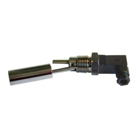
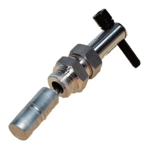
Kobold TWR-1 Series User manual

Operating Instructions
for
Temperature Switch
Model: TWR

TWR
page 2 TWR K15/0923
1. Contents
1.Contents ........................................................................................................ 2
2.Note .............................................................................................................. 3
3.Regulation Use ............................................................................................. 3
4.Operating Principle ........................................................................................ 4
5.Instrument Inspection .................................................................................... 4
6.Use in Hazardous Areas ............................................................................... 5
6.1.General ................................................................................................ 5
6.2.Electrical Contact ................................................................................. 5
6.3.Equipotential Bonding .......................................................................... 5
6.4.Warnings for use in hazardous areas .................................................. 6
7.Mechanical Connection ................................................................................. 7
8.Electrical Connection .................................................................................... 7
9.Maintenance ................................................................................................. 9
10.Accessories ................................................................................................... 9
11.Technical Information .................................................................................. 10
12.Order Codes ............................................................................................... 10
13.Dimensions ................................................................................................. 10
14.Disposal ...................................................................................................... 11
15.Statement of Conformity ............................................................................. 12
16.EU Declaration of Conformance Standard version ..................................... 15
17.EU Declaration of Conformance (ATEX version) ........................................ 16
18.UK Declaration of Conformity Standard version .......................................... 17
Manufactured and sold by:
Kobold Messring GmbH
Nordring 22-24
D-65719 Hofheim
Tel.: +49(0)6192-2990
Fax: +49(0)6192-23398
E-Mail: [email protected]
Internet: www.kobold.com

TWR
TWR K15/0923 page 3
2. Note
Please read these operating instructions before unpacking and putting the unit
into operation. Follow the instructions precisely as described herein.
The instruction manuals on our website www.kobold.com are always for currently
manufactured version of our products. Due to technical changes, the instruction
manuals available online may not always correspond to the product version you
have purchased. If you need an instruction manual that corresponds to the
purchased product version, you can request it from us free of charge by email
([email protected]) in PDF format, specifying the relevant invoice number and
serial number. If you wish, the operating instructions can also be sent to you by
post in paper form against an applicable postage fee.
Operating instructions, data sheet, approvals and further information via the QR
code on the device or via www.kobold.com
The devices are only to be used, maintained and serviced by persons familiar
with these operating instructions and in accordance with local regulations
applying to Health & Safety and prevention of accidents.
When used in machines, the measuring unit should be used only when the
machines fulfil the EC-machine guidelines.
The minimum service life is 100,000 switching cycles at a maximum of 150 °C
when the switching capacities specified in the operating instructions are
observed.
3. Regulation Use
TWR model devices are used to monitor the temperature of liquids. The
temperature switches are delivered with a preset temperature switching value
with N/O or N/C contacts. Only liquids to which the thermostat materials are
resistant should be monitored.

TWR
page 4 TWR K15/0923
4. Operating Principle
The switching element in the model TWR is a thermal time-delay switch. Two
strips of metal with different coefficients of thermal expansion are rolled together
in the switch. When temperature is applied the bimetal reed bends and thus
opens/closes the contact. The switching function is current-independent.
5. Instrument Inspection
The devices are inspected before shipping and are sent out in perfect working
condition. Should there be any visible damage to the device, we recommend that
the delivery packaging is carefully examined. Immediately inform the postal
service or forwarding agency in the event of a claim, as the haulier is responsible
for damage in transit.
Scope of delivery:
The standard delivery includes:
Temperature Switch model: TWR

TWR
TWR K15/0923 page 5
6. Use in Hazardous Areas
6.1. General
The temperature switches TWR-3 **** and TWR-4 **** can be used as follows
(taking into account the notes and the approved electrical limit values):
a) In zone 2 (Gas-Ex, EPL Gc) in explosion group IIA, IIB and IIC
b) In zone 22 (Dust Ex, EPL Dc) in explosion groups IIIA, IIIB and IIIC
The temperature switch also fulfills the requirements for a simple electrical
apparatus according to EN 60079-14 and EN 60079-11 and can be used in
zone 1/21 as follows:
c) In zone 1 (Gas-Ex, EPL Gb) in explosion group IIA, IIB and IIC, if the
temperature switch is operated via an intrinsically safe isolation amplifier
taking into account the defined characteristic data.
d) In zone 21 (Dust Ex, EPL Db) in explosion groups IIIA, IIIB and IIIC, if the
temperature switch is operated via an intrinsically safe isolating amplifier
taking into account the defined characteristic data.
6.2. Electrical Contact
The following limit values for the switching contact must not be exceeded:
Ui = 30 V AC/DC for IIC
45 V AC/DC for IIB and IIIC
Ii = 150 mA for IIC
250 mA for IIB and IIIC
Pi = 1.3 W for IIC and medium temperature up to +40 °C
550 mW for IIC and medium temperature up to +125 °C
750 mW for IIIC and medium temperature up to +40 °C
465 mW for IIIC and medium temperature up to +125 °C
Li = negligible
Ci = negligible
The electrical connection is explained in section 8 Electrical Connection.
6.3. Equipotential Bonding
In order to achieve potential equilibrium, the temperature switch should be
properly grounded. This will occur only when the connection pipes are made of
metal.

TWR
page 6 TWR K15/0923
6.4. Warnings for use in hazardous areas
a) Equalizing currents must not be routed through the metallic constructions.
b) The temperature switch must be installed so that possible electrostatic
charges can be charged off. (Leakage resistance to PA <1 MΩ)
c) The temperature switch should be protected against mechanical shocks.
d) At medium temperatures> 90 ° C the installation must ensure that the
plugs do not overheat.
e) Stuck parts, e.g. by frost or corrosion, must not be released by force in the
presence of an explosive atmosphere.
f) In order to ensure the protection against explosion, electrical equipment
and additional (mechanical) equipment must comply with the requirements
of the local conditions and must be checked separately by the installer of
the machine.
g) The ignition limit curves from EN 60079-11 must be taken into account
without a safety factor and must be complied with during installation.
h) The requirements for simple electrical equipment in the gas and dust
explosion area of zone 1/21 according to EN 60079-11 section 5.7 should
be met.
i) Operation only in intrinsically safe circuits.
j) A power reduction Pi according to 15c) must be complied with at higher
ambient temperatures.
k) The installer / operator must prepare a control drawing (proof of intrinsic
safety) and attach the explosion protection document.

TWR
TWR K15/0923 page 7
7. Mechanical Connection
Before installation:
Make sure that the desired TWR switching temperature and switching function
corresponds with your plant requirements. The TWR data is to be found on the
metal nameplate (OFF = N/C contact, ON = N/O contact at the specified
temperature).
Ensure that the permitted maximum operating pressures for the temperature
switches are not exceeded.
Installation:
The TWR is installed in a G 3/4 fitting. Seal the connection threads with sealing
tape or a flat gasket.
Chose the installation position so that the sensor tip is always immersed in the
liquid, thus optimising the heat exchange between medium and temperature
switch.
Please note that solid deposits in soiled media may cause thermal
insulation and thus inaccuracies.
If possible, after mechanical installation, check that the joint connection pipe
fitting is sealed.
8. Electrical Connection
Important! Ensure that voltage and current values in your plant do
not exceed the temperature switch values.
Make sure that electrical supply lines are de-energized.
Undo the retaining screw from the plug cap and remove the cap from the plug
socket.
Install the supply line in the plug cap according to the wiring diagram below.
Mount the connector on the contact base and fasten with the retaining screw.
The device is ready for operation when you have connected your external
devices to the limit output.

TWR
page 8 TWR K15/0923
Contacts
21
TWR-1...
21
TWR-2...
TWR-3... TWR-4...
TWR-1/3...
TWR-2/4..., N/O function
The contact closes when the
temperature rises and the switching
value has been reached or
exceeded. It opens again when the
temperature falls below the limit
value less the switching hysteresis.
Electrical wiring option –L and –G
(The circuit is placed inside of the connector in parallel to the contact, not for
ATEX version):
Option –L (24VAC/DC Option –G (230VAC)

TWR
TWR K15/0923 page 9
Hysteresis
Hysteresis is the difference between make and break points, which are at
different temperatures. The hysteresis is max.20 °C.
Example: TWR-110500
Contact opens at 50 °C ±5 °C
Contact closes at approximately 30 °C ±5 °C
Note: Temperature switches with low switching temperatures, when
used at high ambient temperatures, are only reset when the switch
is cooled to below the ambient temperature.
Example: TWR-210300, ambient temperature 25 °C
Contact closes at 30 °C ±5 °C
Contact opens at approximately 10 °C ±5 °C
(i.e., below ambient temperature)
9. Maintenance
The TWR requires no maintenance if the measured medium is clean. Dirt
deposits can cause inaccuracies or a malfunction. Depending on the degree of
soiling of your medium, we recommend that the devices are checked at regular
intervals.
10. Accessories
10.1) 2-pin connector with lamp 180–240 VAC incl. silicone gasket
(energized if contact is open)
10.2) 2-pin connector with LED 24 VDC/AC incl. silicone gasket
(energized if contact is open)

TWR
page 10 TWR K15/0923
11. Technical Information
Operating instructions, data sheet, approvals and further information via the QR
code on the device or via www.kobold.com
12. Order Codes
Operating instructions, data sheet, approvals and further information via the QR
code on the device or via www.kobold.com
13. Dimensions
Operating instructions, data sheet, approvals and further information via the QR
code on the device or via www.kobold.com

TWR
TWR K15/0923 page 11
14. Disposal
Note!
Avoid environmental damage caused by media-contaminated parts
Dispose of the device and packaging in an environmentally friendly
manner
Comply with applicable national and international disposal regulations and
environmental regulations.
Batteries
Batteries containing pollutants are marked with a sign consisting of a crossed-out
garbage can and the chemical symbol (Cd, Hg, Li or Pb) of the heavy metal that
is decisive for the classification as containing pollutants:
Cd1 Hg2 Pb3 Li4
1. „Cd" stands for cadmium
2. „Hg" stands for mercury
3. „Pb" stands for lead
4. „Li" stands for lithium
Electrical and electronic equipment

TWR
page 12 TWR K15/0923
15. Statement of Conformity

TWR
TWR K15/0923 page 13

TWR
page 14 TWR K15/0923

TWR
TWR K15/0923 page 15
16. EU Declaration of Conformance Standard version
We, KOBOLD Messring GmbH, Nordring 22-24, 65719 Hofheim, Germany,
declare under our sole responsibility that the product:
Temperature Switch Model TWR-...
to which this declaration relates is in conformity with the following EU directives
stated below:
2014/35/EU Low Voltage Directive
2011/65/EU RoHS (category 9)
2015/863/EU Delegated Directive (RoHS III)
Also, the following standards are fulfilled:
EN 60529:2014
Degrees of protection provided by enclosures (IP Code)
EN IEC 63000:2018 Technical documentation for the assessment of electrical
and electronic products with respect to the restriction of hazardous substances
Hofheim, 04 Sept. 2023
H. Volz J. Burke
General Manager Compliance Manager

TWR
page 16 TWR K15/0923
17. EU Declaration of Conformance (ATEX version)
We, KOBOLD Messring GmbH, Nordring 22-24, 65719 Hofheim, Germany,
declare under our sole responsibility that the product:
Device: Temperature Switch Model TWR-...
Fulfills all relevant requirements of the following directive(s):
2014/34/EU Devices and protective systems for the intended use in
potentially explosive atmospheres
The following harmonized standards have been applied for conformity
assessment:
EN IEC 60079-0:2018 Equipment - General requirements
EN 60079-11:2012 Equipment protection by intrinsic safety "i"
Ex marking:: II 3G Ex ic IIB/IIC T4 Gc
II 3D Ex ic IIIC T125 °C Dc
For installation in zones 1/22:
The TWR fulfils the requirements for simple electrical apparatus according to EN
60079-14 and EN 60079-11. When operated via an intrinsically safe isolating
amplifier, it is suitable for installation in Zone 1/21.
The safety instructions for explosion protection in the manufacturer's operating
instructions must be observed.
The product also complies with the following EU directives and EU standards:
2011/65/EU RoHS (category 9)
2015/863/EU Delegated Directive (RoHS III)
EN IEC 63000:2018 Technical documentation for the assessment of
electrical and electronic equipment with regard to the restriction of
hazardous substances
Hofheim, 04. Sept. 2023
H. Volz J. Burke
General Manager Compliance Manager

TWR
TWR K15/0923 page 17
18. UK Declaration of Conformity Standard version
We, KOBOLD Messring GmbH, Nordring 22-24, 65719 Hofheim, Germany,
declare under our sole responsibility that the product:
Temperature Switch Model TWR-...
to which this declaration relates is in conformity with the following UK directives
stated below:
S.I. 2016/1101 Electrical Equipment (Safety) Regulations 2016
S.I. 2012/3032 The Restriction of the Use of Certain Hazardous
Substances in Electrical and Electronic Equipment
Regulations 2012
Also, the following standards are fulfilled:
BS EN 60529:1992+A2:2013
Degrees of protection provided by enclosures (IP-Code)
BS EN IEC 63000:2018
Technical documentation for the assessment of electrical and electronic products
with respect to the restriction of hazardous substances.
Hofheim, 04 Sept. 2023
H. Volz J. Burke
General Manager Compliance Manager
This manual suits for next models
3
Table of contents
Other Kobold Switch manuals

Kobold
Kobold NBA-2 User manual

Kobold
Kobold NV Series User manual

Kobold
Kobold SCH User manual

Kobold
Kobold NCG NCM Series User manual

Kobold
Kobold LNK User manual

Kobold
Kobold LNZ User manual
Kobold
Kobold BVO Series User manual

Kobold
Kobold NSED User manual

Kobold
Kobold NBK-RA User manual

Kobold
Kobold TDD User manual

Kobold
Kobold NSP User manual

Kobold
Kobold NE-104 User manual
Kobold
Kobold NBK-RV200NO User manual
Kobold
Kobold NGS User manual

Kobold
Kobold PSC series User manual

Kobold
Kobold NSV Series User manual

Kobold
Kobold PPS-1201 User manual

Kobold
Kobold PPS User manual

Kobold
Kobold TDD-153 series User manual

Kobold
Kobold SCH-27 User manual