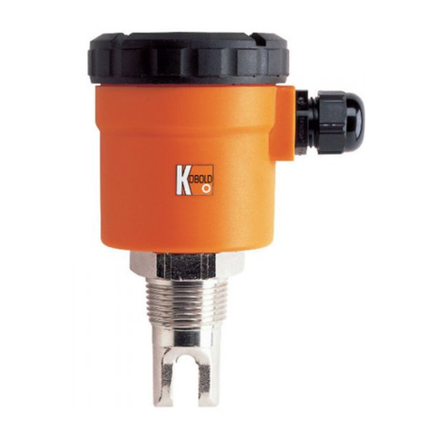
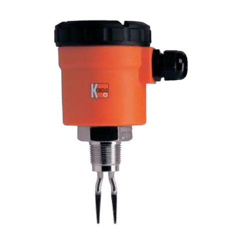
Kobold NVI User manual

Operating Instructions
for
Vibrating Level Switches
Model: NVI

NVI
page 2 NVI K04/0517
1.Contents
1.Contents........................................................................................................2
2.Note ..............................................................................................................3
3.Instrument Inspection....................................................................................3
4.Regulation Use..............................................................................................3
5.Operating Principle........................................................................................4
6.Mechanical Connection.................................................................................4
7.Electrical Connection ....................................................................................7
7.1General................................................................................................7
7.2Operation Diagram ..............................................................................7
8.Commissioning..............................................................................................8
8.1Density (Sensitivity) Adjustment (Switch A).........................................8
8.2High/Low Fail-Safe Mode (Switch C)...................................................8
8.3Time Delay (Switch B) .........................................................................8
9.Technical Information....................................................................................9
10.Derating Diagram........................................................................................10
11.Order Codes ...............................................................................................10
12.Maintenance ...............................................................................................10
13.Storage .......................................................................................................11
14.Guarantee...................................................................................................11
15.Dimensions .................................................................................................11
16.EU Declaration of Conformance..................................................................12
Manufactured and sold by:
Kobold Messring GmbH
Nordring 22-24
D-65719 Hofheim
Tel.: +49(0)6192-2990
Fax: +49(0)6192-23398
Internet: www.kobold.com

NVI
NVI K04/0517 page 3
2.Note
Please read these operating instructions before unpacking and putting the unit
into operation. Follow the instructions precisely as described herein.
The devices are only to be used, maintained and serviced by persons familiar
with these operating instructions and in accordance with local regulations
applying to Health & Safety and prevention of accidents.
When used in machines, the measuring unit should be used only when the
machines fulfil the EC-machine guidelines.
3.Instrument Inspection
Instruments are inspected before shipping and sent out in perfect condition.
Should damage to a device be visible, we recommend a thorough inspection of
the delivery packaging. In case of damage, please inform your parcel service /
forwarding agent immediately, since they are responsible for damages during
transit.
Scope of delivery:
The standard delivery includes:
Vibrating Level Switch model NVI
Operating Instructions
4.Regulation Use
Any use of the Vibrating Level Switch, model: NVI, which exceeds the
manufacturers specification may invalidate its warranty. Therefore any resulting
damage is not the responsibility of the manufacturer. The user assumes all risk
for such usage.

NVI
page 4 NVI K04/0517
5.Operating Principle
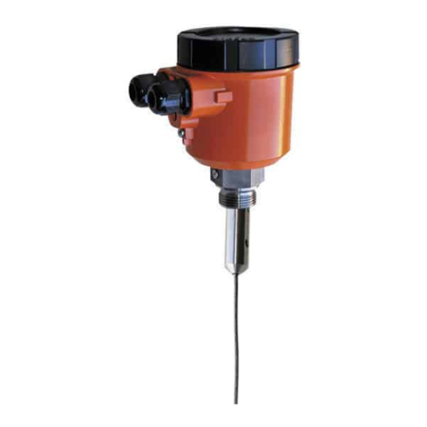
The KOBOLD NVI level switch is a mechanical system that is made to resonate
by an electronic switching operation. When the probe is covered by a medium,
the vibrations are damped. This change in the resonance frequency is converted
to a switching signal by electronic means.
The combined vibrating switch can be used in powdery media and granular
materials. The medium to be measured should have a density of at least 0.05
kg/dm3. The single rod design prevents deposit formation. The rod is self-
cleaning, as the vibrations shake off the medium.
6.Mechanical Connection
Important! Handle the device with great care, especially the sensing
probe. A larger impact on the sensing probe may ruin its resonance
system. Probes exposed to falling material or mechanical loads
should be protected.
Prior to the installation, it is advised to test the switching function of the unit on
a sample quantity of material and to set „Density“ switch according to the
density of medium. (see 8. Commissioning)
Screw in the device by its hexagon neck. After screwing tight the process
connection, the housing can be rotated (max. 300 °), to adjust the cable glands
to the required position. In some cases such as material caving or arching you
will need to mount the vibration rod at a clearance from the desired limit.
The model NVI is not suggested to be used for low level detection in high
density materials.
Max. switching Min. switching

NVI
NVI K04/0517 page 5
Limits for bending or pulling force and torque should be considered:
R_H
R_R
R_L
R_K
R_C
F = 500 N
M = 100 Nm M = 100 Nm F = 45 kN
Powder Granulate

NVI
page 6 NVI K04/0517
Probes exposed to falling material or mechanical loads should be protected.
L30x30x3
When working with powdery bulk materials you should install the device at an
inclination greater than the existing angle of repose, or even vertically to detect
maximum level. This is necessary in order to prevent too much powder clinging
to the vibration rod and hindering vibration and self-cleaning of the rod when
the silo/tank is being emptied. Avoid mounting the device as shown in the
diagram.
Use rubber shims for example to protect the device in bins/silos where large
vibrations occur.

NVI
NVI K04/0517 page 7
7.Electrical Connection
7.1 General
Attention! Check that the electrical power supply to the instrument
complies with the operating data for the instrument.
AC = Switch rating acc. To EN60947-1
NO CNC
PE
NL1
PE
NL1
123 456
250VAC
8A/AC1
A
B CStatus LED
Relay output version
Attention! Incorrect wiring will lead to damage of the unit’s
electronics.
7.2 Operation Diagram
Power Probe Fail-safe mode LED RELAY
ON
NOT
VIBRITING
(COVERED)
LOW GREEN
54
6
ENERGISED
HIGH RED
54
6
DE-ENEGISED
VIBRITING
(FREE)
LOW RED
54
6
DE-ENEGISED
HIGH GREEN
54
6
ENERGISED
FAILS LOW
OR
HIGH NOT LIT
54
6
DE-ENEGISED

NVI
page 8 NVI K04/0517
8.Commissioning
Unscrew the housing cover to access the terminals and setting switches. Do not
disconnect the wire from terminal connection point 1. Ground the device at
terminal PE or use the grounding screw on the device.
When you have properly connected the device, it is ready for operation. The LED
lights up when the device is switched on.
8.1 Density (Sensitivity) Adjustment (Switch A)
The DIP-Switch DENSITY (switch A) needs to be set to suit the material density.
LOW position, recommended for loose and light materials with density around
and below 0.1 kg/dm³ represents low energy and amplitude of vibration as
well as great sensitivity of detection.
HIGH position, recommended for (thick and heavy) materials with density over
0.1 kg/dm³ represents vibration with high energy and amplitude and small
sensitivity of detection.
8.2 High/Low Fail-Safe Mode (Switch C)
De-energised status of the relay is preferred to be used for fail-safe alarm, thus a
power breakdown will be considered as alarm (see 7.2 Operation Diagram)
8.3 Time Delay (Switch B)
Though the density of the medium is within the specific range, the device may not
detect if the internal friction of the medium is too low. Choose a switch delay
(switch B) to suit process requirements (standard response time, switch delay
= 5 s; short response time, switch delay = 2 s).
Note: The device can be damaged by electrostatic discharge
(e.s.d.) from the DIP switch. To prevent such damage, the
general precautions must be strictly observed.

NVI
NVI K04/0517 page 9
9.Technical Information
Probe length: 207 mm (standard)
pipe extended version: up to 3 m
cable extended version, PE coated:
up to 20 m
Process connection: G 1 1/2 or 1 ½” NPT
Housing material: aluminium, powder coated
Material for
wetted parts: 1.4571 (AISI316Ti) for vibrating probe
PE cover for cable
Sensor surface: bright
Medium temperature: -30 °C...+110 °C standard probe
-30 °C...+80 °C (NVI-5)
-30 °C...+160 °C high temperature
Ambient temperature: -30 °C...+60 °C
Maximum pressure: 25 bar (NVI-1/2/3/4)
6 bar (NVI-5)
Minimum density
of medium: 0.05 kg/l
Max. grain size: 10 mm
Max load:
Version Standard Pipe extended Cable extended
High limit switch Side mounted Top mounted Top mounted
Low limit switch Side or bottom
mounted
Loadability
Force 500 N - 45 kN
Torque 100 N 100 Nm -
Switching delay
(selectable): 1.8 s or 5 ± 1.5 s
(selectable) with covered rod
2 s or 5 ± 1.5 s
rod swings freely
Output: changeover contact 250 VAC /8 A
Power supply: 20...255 VAC/DC; ≤2.5 VA/2 W
Electrical connection: 2xM20x1.5
Protection: IP 67
Weight: approx. 1.9 kg (NVI-1/2)
approx. 3.3 kg (NVI-3/4)
approx. 2.5 kg (NVI-5)

NVI
page 10 NVI K04/0517
10. Derating Diagram
-30
-30 50 75
0
0
60
50
35
20
100 110 160 T
[°C]
A
M
T
[°C]
Ambient temperature (TA) versus medium temperature (TM)
11. Order Codes
Example: NVI-1 305 R
Model Version Power supply Connection
NVI-
1 = standard probe
2 = standard probe,
high-temperature 305 = 20...255 VAC/DC R = G 1 ½
N = 1 ½” NPT
3* = pipe extended
4* = pipe extended,
high temperature
5* = cable extended
* Mention desired length in clear text (in mm).
12. Maintenance
Series NVI devices require no regular maintenance. You may need to remove
product stuck to the vibrating section and clean the vibrating section every now
and then. Handle the vibrating section of the vibration rod with great care to
avoid any damage.
The manufacturer will carry out all repairs within and beyond the guarantee
period. Clean or disinfect all parts before returning them for repair.

NVI
NVI K04/0517 page 11
13. Storage
Ambient temperature:-35 up to +60 °C
Relative humidity: max. 98 %
14. Guarantee
All guarantee repair work will be carried out in the manufacturer's workshop. The
costs of demounting, installation, and transportation shall be borne by the
purchaser.
All rights to claims under guarantee for faults caused by incorrect installation,
rupture, improper handling or force majeure will not be honoured.
15. Dimensions
Standard probe Pipe extended probe Cable extended probe

NVI
page 12 NVI K04/0517
16. EU Declaration of Conformance
We, Kobold Messring GmbH, Hofheim-Ts, Germany, declare under our sole
responsibility that the product:
Vibrating Level Switches Model: NVI
to which this declaration relates is in conformity with the standards noted below:
EN 61010-1:2011 Safety requirements for electrical equipment for
measurement, control and laboratory use – Part 1: General requirements
EN 61326-1:2013 Electrical equipment for measurement, control and
laboratory use - EMC requirements – Part 1: General requirements
EN 61326-2-3:2013 Electrical equipment for measurement, control and
laboratory use - EMC requirements - Part 2-3: Particular requirements - Test
configuration, operational conditions and performance criteria for transducers with
integrated or remote signal conditioning
Also the following EU guidelines are fulfilled:
2014/30/EU EMC Directive
2011/65/EU RoHS
Furthermore for equipment with supply voltage < 48 V:
2014/35/EU Low Voltage Directive
Hofheim, 11. May 2017
H. Peters M. Wenzel
General Manager Proxy Holder
Table of contents
Other Kobold Switch manuals

Kobold
Kobold NEK Series User manual

Kobold
Kobold NSV Series User manual

Kobold
Kobold NBK-RA User manual

Kobold
Kobold NQ series Installation instructions

Kobold
Kobold NSM User manual

Kobold
Kobold TWR User manual

Kobold
Kobold SMN User manual

Kobold
Kobold NE-104 User manual

Kobold
Kobold KAL-L User manual

Kobold
Kobold NBK-RV200NO User manual

Kobold
Kobold KAL-8115FL User manual

Kobold
Kobold NGS User manual

Kobold
Kobold NV User manual

Kobold
Kobold TDD Series User manual

Kobold
Kobold NSED User manual
Kobold
Kobold SCH-27 User manual

Kobold
Kobold RFS User manual

Kobold
Kobold NAS User manual

Kobold
Kobold AFS-G3 User manual

Kobold
Kobold NV Series User manual