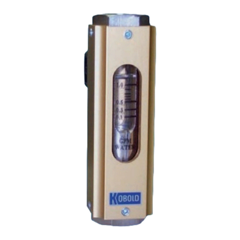
Kobold SMN User manual

Operating Instructions
for
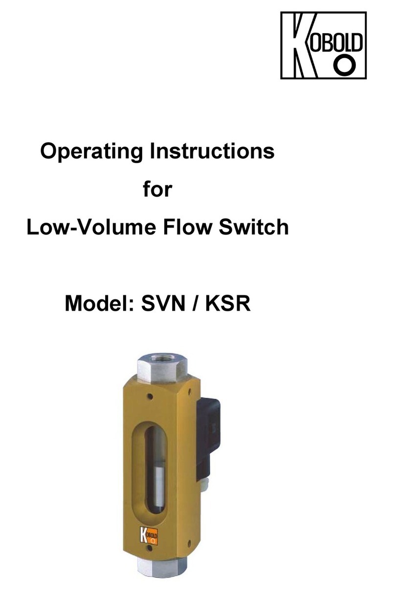
All Metal Flow Switch
Model: SMN

SMN
Seite 2 SMN K02/0416
1.Contents
1.Contents............................................................................. 2
2.Note.................................................................................... 3
3.Instrument Inspection ......................................................... 3
4.Regulation Use................................................................... 3
5.Operating Principle............................................................. 4
6.Use in Hazardous Areas..................................................... 4
6.1.General 4
6.2.Electrical Contacts 5
6.3.Potential Equalisation 5
7.Mechanical Connection ...................................................... 5
8.Electrical Connection.......................................................... 6
8.1.with Plug Connection 6
8.2.Example for Contact Protective Measures 6
9.Commissioning................................................................... 7
10.Maintenance and Care ....................................................... 7
11.Technical Information ......................................................... 8
12.Order Codes....................................................................... 9
13.Dimensions......................................................................... 9
14.Pressure Loss Diagram.................................................... 10
15.Declaration of the Manufacturer ....................................... 10
16.EU Declaration of Conformance....................................... 12
Manufactured and sold by:
Kobold Messring GmbH
Nordring 22-24
D-65719 Hofheim
Tel.: +49(0)6192-2990
Fax: +49(0)6192-23398
Internet: www.kobold.com

SMN
SMN K02/0416 Seite 3
2.Note
Please read these operating instructions before unpacking and putting the unit
into operation. Follow the instructions precisely as described herein.
The devices are only to be used, maintained and serviced by persons familiar
with these operating instructions and in accordance with local regulations
applying to Health & Safety and prevention of accidents.
When used in machines, the measuring unit should be used only when the
machines fulfil the EC-machine guidelines.
as per PED 2014/68/EU
In acc. with Article 4 Paragraph (3), "Sound Engineering Practice", of the
PED 2014/68/EU no CE mark.
Table 8, Pipe, Group 1 dangerous fluids
3.Instrument Inspection
Instruments are inspected before shipping and sent out in perfect condition.
Should damage to a device be visible, we recommend a thorough inspection of
the delivery packaging. In case of damage, please inform your parcel service /
forwarding agent immediately, since they are responsible for damages during
transit.
Scope of delivery:
The standard delivery includes:
All Metal Flow Switch model: SMN
Operating Instructions
4.Regulation Use
Model SMN instruments monitor liquid flows. Only clean and homogeneous
liquids of low viscosity - against which the instrument materials are resistant -
should be monitored. Large switch-point inaccuracies can occur with highly
viscous media.
Large dirt particles can block the float and thus cause faulty signals. Pieces of
ferrite, deposited on the float (with embedded magnet) can lead to the same
effect (we recommend magnetic filters).

SMN
Seite 4 SMN K02/0416
5.Operating Principle
The KOBOLD model SMN flow switch is used when extremely low flow switch
points are required in combination with minimum pressure loss at high flow rates.
The flow switch operates on the well-known float principle.
An orifice float with an integrated circular magnet moves within a cylindrical flow
tube in the direction of the flow and against a spring.
The magnetic field of the float activates a reed contact which is mounted on the
outside of the instrument in a sliding protective casing. Due to the special
construction of the float and flow tube only a low flow is required to raise the float
and hence to activate the reed contact. If the flow rate increases further and the
float reaches the top of its travel an additional flow path opens allowing high flow
rates without a significant increase in the pressure loss.
6.Use in Hazardous Areas
6.1. General
The All Metal Flow Switch does not have a potential igniting source of his own as
a mechanical operating resource; it does not get any identification according
to the guideline 94/9/EC ("ATEX 100a”).
The add-on control contacts can under application of EN 60079-14 be used as a
“simple operator” (simple electrical equipment) without other marking in
intrinsically safe equipment. The following limit values for the switching contact
should not be exceeded: U = 30 VDC, I = 100 mA, P = 1,2 W. It does not get any
identification according to the ATEX-guideline.
The units can be used as follows:
a) In the Zone 2 (Gas-Ex, Cat. 3G) into explosion group of IIA, IIB and IIC
b) In the Zone 22 (Dust-Ex, Category 3D) at non-conductive dusts with a
minimum igniting energy of > 3 mJ
c) In the Zone 1 (Gas-Ex, Cat. 2G) into explosion group of IIA, IIB and IIC
d) In the Zone 21 (Dust-Ex, Category 2D) at non-conductive dusts with a
minimum igniting energy of > 3 mJ
The Flow Switch is filled completely with medium in the normal operation. Zone 2
or zone 1 conditions may be obtained for a short time.

SMN
SMN K02/0416 Seite 5
The ambient temperature limit area is fixed as follows:
Execution Medium Temperature Pmax
SMN-11... -20...+100 °C 250 bar
SMN-12... -20...+100 °C 350 bar
6.2. Electrical Contacts
The Flow Switch can be used in the Ex-area according Category 2G and 2D
Cluster II; in zone 1 and 21 in connection with a switching amplifier for protection
type Ex II (2)GD [EEx ia] IIC (intrinsically safe)
The electrical connection is explained in section 8. Electrical Connection.
6.3. Potential Equalisation
The All Metal Flow Switches have to be included in the equipotential bonding
system of the installation. This is done by the connection tube made out of metal.
7.Mechanical Connection
Make sure that allowed max. operating pressure and temperature are not
exceeded.
The instrument can be installed vertically or horizontally in the pipework. Flow
is in the direction of the arrow from bottom to top, from left to right or from right
to left.
Remove all transport restraints and make sure that none of the packing
material remains in the instrument.
Use Teflon tape or something similar to seal the threaded connections.
The instruments should not be installed in an induction field.
If possible, check after mechanical installation that the threaded joint/pipe
connection is tight and leakproof.

SMN
Seite 6 SMN K02/0416
8.Electrical Connection
8.1. with Plug Connection
Make sure that the electrical supply lines are powerless.
Undo the locking screw on the plug cap and remove the cap
from the base.
Mount supply line in the plug cap as shown in the wiring
diagram.
The contact is adjusted and should not be modified.
Insert the plug connector on the contact stem and fix it with
the retaining screw.
Attention! Every single specified electrical value for the sealed
contact should not be exceeded even for short periods. We
recommend contact protection relays or other contact protection
measures for higher switching values.
When the external devices have been connected to the limit contact and the
switching point has been set, the electrical connection is complete. The instrument
can now be put into operation.
8.2. Example for Contact Protective Measures
For capacitive and inductive loads (long conductors and relay/protection) we
recommend the following protective schemes.

SMN
SMN K02/0416 Seite 7
9.Commissioning
When used in machines according to guideline 2006/42/EC commissioning is
prohibited until it is established that the machine meets the general requirements
of the guideline.
The limit switch is adjusted.
10. Maintenance and Care
The instrument needs no maintenance when the measured medium is not
polluted. Lime and other deposits should be removed regularly from the inside
parts of the instruments. The instrument cannot be taken apart and must be
cleaned with a suitable cleanser.

SMN
Seite 8 SMN K02/0416
11. Technical Information
Housing: SMN-11..: brass, Ms 58
SMN-12..: stainless steel, 1.4301
Float: SMN-11..: brass, Ms 58
SMN-12..: stainless steel, 1.4301
Cage: SMN-11..: brass, Ms 58
SMN-12..: stainless steel, 1.4301
Spring: stainless steel
Magnets: Ceramic
Max. temperature: 100 °C
Max. pressure: SMN-11..: 250 bar
SMN-12..: 350 bar
Installation position: horizontal or vertical (upward direction),
flow in direction of the arrow
Contact components: 1 bistable reed contact
N/O contact, changeover contact,
Electrical connection: Connector DIN 43 650
Electrical switching values: N/O contact (standard)
max. 250 VAC/DC / 1,5 A / 100 W / 100 VA
changeover contact (Standard)
max. 250 VAC/DC / 1 A / 30 W / 60 VA
N/O contact and changeover contact (cCSAus)
max. 230 VDC / 0,26 A / 60 W,
60 VDC / 1 A / 60 W
max. 240 VAC / 0,42 A / 100 W,
100 VAC / 1 A / 100 W
Ex-range: ATEX-Zone 1 as “simple operator”
Accuracy: ± 5% f. s.
Protection type: IP 65

SMN
SMN K02/0416 Seite 9
12. Order Codes
Order Details (Example: SMN-1150H R0 R 25)
Function Brass
version Stainless steel
version Type of contact Connection
Max Flow:
100 l/min
Fix Switch
point at
approx. 1l/min
with falling
flow rate
SMN-1150 H... SMN-1250 H...
..R0.. = 1 N/O contact
..U0.. = 1 changeover
contact
..C0.. = 1 N/O contact
(cCSAus)
..D0.. = 1 changeover
contact
(cCSAus)
...R25 = G1
female
...N25 = 1 NPT
female
13. Dimensions
SMN
OBOLD
Min.15 88.5
G 1
40 120
Flow
Switch
KOBOLDMessring GmbH
Nordring 24
D-65719 Hofheim / Ts
Fax (06192)23398

SMN
Seite 10 SMN K02/0416
14. Pressure Loss Diagram
15. Declaration of the Manufacturer
Declaration for equipment without a potential igniting source according to
the explosion protection guideline 94/9/EC (ATEX 95).
We, KOBOLD Messring GmbH, herewith declare that the following units and/or
assembly groups:
All Metal Flow Switch of the model SMN
according to guideline 94/9/EG, article 1 paragraph 2 and 3 are
a. no safety, controlling and regulating equipment,
b. no devices,
c. no protection systems and
d. no components.
The Flow Switch does not have a potential igniting source of its own as a
mechanical operating resource and/or does not carry any internal explosive
atmosphere; it does not get any identification according to the ATEX guideline.
An internal danger of ignition was accomplished.
0,5
0,4
0,3
0,2
0,1
10 20 30 40 50 60 70 80 90 10
0
P
ressure
l
oss
p (bar)
Q
(
l/min
)

SMN
SMN K02/0416 Seite 11
The units / assembly groups can be used as follows:
a. In the Zone 2 (Gas-Ex, Cat. 3G) into explosion group of IIA,
IIB and IIC
b. In the Zone 22 (Dust-Ex, Category 3D) at non-conductive dusts
with a minimum igniting energy of > 3 mJ
c. In the Zone 1 (Gas-Ex, Cat. 2G) into explosion group of IIA,
IIB and IIC
d. In the Zone 21 (Dust-Ex, Category 2D) at non-conductive dusts
with a minimum igniting energy of > 3 mJ
The heating is negligible, a limit value of 20 K must be accounted for the ambient
temperature and the temperature classification and/or the maximum surface
temperature.
The following harmonised norms were used in the version current for the
signature date.
EN 1127-1 Potentially Explosive Atmosphere, Explosion Protection, part 1:
Basics and Methodology
The operation instructions with the broader details listed within and the
installation regulations for the potentially explosive atmosphere have to be
definitely observed. Some essential measures are:
a. The Flow Switch has to be involved in the equipotential bonding
system.
b. Add-on control contacts can under application of EN 60079-14 article
12.2.1 being used as simple electrical equipment without other
marking in intrinsically safe equipment.
Hofheim, 16. Jan. 2007
H. Peters M. Wenzel
General Manager Proxy Holder

SMN
Seite 12 SMN K02/0416
16. EU Declaration of Conformance
We, KOBOLD-Messring GmbH, Hofheim-Ts, Germany, declare under our sole
responsibility that the product:
All Metal Flow Switch model: SMN-...
to which this declaration relates is in conformity with the standards noted below:
EN 61010-1:2011
Safety requirements for electrical equipment for measurement, control and
laboratory use - Part 1: General requirements
EN 60529:2014
Protection type through case (IP code)
Also the following EC guideline is fulfilled:
2014/35/EU Low Voltage Directive
2011/65/EU RoHS (category 9)
94/9/EG Equipment and Protective systems intended for
use in potentially Explosive Atmospheres (ATEX 100a)
Quality Management Production
Certificate number: BVS 15 ATEX ZQS / E 110
Notified body: Deutsche Montan Technologie
Identification number: 0158
Hofheim, 27. April 2016
H. Peters M. Wenzel
General Manager Proxy Holder
Table of contents
Other Kobold Switch manuals

Kobold
Kobold PSC series User manual

Kobold
Kobold NBK-RPVC User manual

Kobold
Kobold NEK Series User manual

Kobold
Kobold AFS-G3 User manual

Kobold
Kobold NWS User manual

Kobold
Kobold NV Series User manual

Kobold
Kobold NAB User manual

Kobold
Kobold LNK-K User manual

Kobold
Kobold NV User manual

Kobold
Kobold NQ series Installation instructions
Popular Switch manuals by other brands

Leviton
Leviton OSSNL-ID Specifications

TRC
TRC Surge Guard 40350 RVC troubleshooting guide

AVGear
AVGear AVG-UHS24 user manual

Accton Technology
Accton Technology Classic-2040 Quick installation guide

North American Cable Equipment
North American Cable Equipment IP-POE24M Hardware installation manual

Cisco
Cisco ME 3400E Hardware installation guide