Kodicom KSR816 User manual

•This manual is published by KODICOM Co, Ltd and contains information on KSR816 which
will enable you to use this product properly.
• If you require additional copies of this manual, please print the manual contained in the CD
provided with your purchase.
KKSSRR881166MMaannuuaall

Thank you for purchasing KODICOM KSR816 .
This DVR is produced by the most advanced KODICOM technology and its quality is
guaranteed by strict reliability and compatibility testing.
This KSR816 manual provides necessary information for the correct use of this product and
also contains some useful tips.
Please read this manual thoroughly before using KSR816 in order to prevent possible
breakdown due to any mishandling.
IInnttrroodduuccttiioonn

All copyrights of this manual are reserved by KODICOM CO., Ltd.
Copyright®œ 2003
It is prohibited to copy or republish this manual for commercial reasons.
It is prohibited to transfer this manual via online media such as, but not limited to, the Internet. It is
also prohibited to post, distribute, or translate this manual without KODICOM’S permission.
KODICOM is not held responsible if the DVR is damaged due to the system being handled
inappropriately by a user who is not aware of how to operate this product, or by a user who did not
refer to this manual before attempting to operate the product.
KODICOM reserves the right to change the contents of this manual without notice.
KODICOM reserves all copyrights of registered trademarks in this manual.
CCooppyyrriigghhtt
User’s guide for KSR816 DVR.
This manual applies to KSR816 DVR only.
This manual describes external features of the KSR816 DVR, part names, correct connection
methods for supported domes or Pan/Tilt receivers, control devices, peripheral devices, and
the system set up instructions. It should be noted that some features, figures, pictures and
references can only be applied to one model either KSR816.
•KODICOM can not be held responsible if the DVR is damaged due to non-compatible
devices being used with this product. If you have any doubts please check.
•KODICOM can not be held responsible if the DVR is damaged due to the product being
disassembled or modified by the user.
•If you wish to open the system casing to attempt to modify, repair, or upgrade the system, it
is recommended that you ask for a KODICOM engineer’s assistance by contacting either
your dealer or KODICOM head office.
•DigiNet and KSR816 are registered trademarks of Korea Digital Communication
(KODICOM).
•This product is qualified for both domestic and industrial use. This product is qualified under
the Radio Equipment Requirements of Korea and acquired international certification
including CE (Europe) and FCC (USA).
NNoottiiccee

Please beware of the following precautions before installing the DVR.
•Avoid positioning the KSR816 in any place where the unit may come into contact
with moisture, dust, or soot.
•Avoid placing in direct sunlight or near heating appliances.
•Keep the product away from electric shock or magnetic substances.
•Avoid temperature extremes (recommended operation temperature is between 0°C
and ~40°C).
•Do not place any conductive material through the ventilation grills.
•Keep the system turned off before installation.
•Ensure enough space is left for cable connections.
•Place the system on a solid surface with sufficient air ventilation. Avoid any surface
that vibrates.
•Placing the system near electronic devices such as radio or TV may cause breakdown
to the product.
•Do not disassemble the product without seeking assistance from KODICOM.
•Do not place any heavy object on the system.
CCaauuttiioonn
The following are warnings and cautions for the safety of the users and for the prevention of any
property damage. Please read below thoroughly.
Safety Warnings and Cautions
Warning and Caution signs
If you are not aware of this
warning, you may be seriously
injured or be killed.
If you are not aware of this
caution, you may be injured
or cause property loss.
Do not place any liquid container on the
system, such as water, coffee, or beverage.
If liquid is poured onto the system, it can
cause a system breakdown or cause fire.
Prevent power cable from being severely
bent or pressed by a heavy object.
This may cause fire.
Avoid any place with moisture, dust, or soot.
This can cause fire or electric shock. When pulling the power cable from the
plug, do so gently. Do not touch the
plug with wet hands and avoid using
the plug if the holes on the outlet are
too loose.
This may cause
fire or electric
shock.
Turn off the system before installing the
system. Do not plug in several electric
devices to the same outlet.
This may cause heating, fire, or electric
shock.
Clean the dust around the system on regular
basis. When cleaning the system, always use
dry cloth. Do not use wet cloth or other organic
solvents.
This may damage the
surface of the system
and can cause system
breakdown or electric
shock.

D not attempt to disassemble, repair, or
modify the system on your own. It is
extremely dangerous due to high voltage
running through the system.
This may cause fire, electric shock, or
serious injuries.
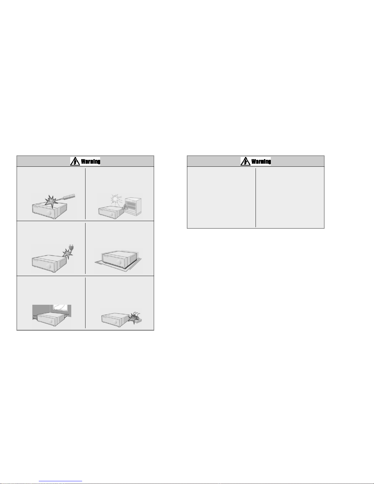
Install the system in a cool place without
direct sunlight and always maintain room
temperature. Avoid candle light and heat-
generating devices such as heater. Keep
the system away from places where
many people pass.
This may
cause fire.
Install the system on a plain surface with
sufficient air ventilation. Do not place the
system on elevated surface.
This may cause system breakdown or
serious injuries.
Keep at least 15cm between the back of
the system and a wall for the cables
connected into the system. Otherwise,
cables may be bent, damaged, or cut.
This may cause fire, electric shock, or
injuries.
When the system’s battery is deplete, you
must change it with the same or
equivalent type of battery specified by the
manufacturer. Depleted batteries should
be discarded according to manufacturer’s
instructions.
This may cause an explosion.
If the system’s HDD exceeded its life
span, you may not be able to recover any
data stored inside the HDD. If the video
on the system screen appears ‘damaged’
while playing a recording stored inside the
system’s HDD, it must be replaced with a
new one. Ask for an engineer’s assist
ance for HDD replacement from your
dealer.
KODICOM is not responsible for
deleted data caused by user’s
mishandling.
Check for any danger signs such as moist
floor, loosened or damaged power cable,
or unstable surface. If you encounter any
problems, ask for assistance from your
dealer.
This may cause fire or
electric shock.
The power outlet must be placed on a
ground, and the voltage range must be
within 10% of the voltage rate. Do not
use the same outlet with a hair dryer,
iron, refrigerator, or any heating
appliances.
This may cause fire, heating, an
electric shock.

The system can be damaged from a
strong impact or vibration. Avoid throwing
objects within the vicinity of the system.
The outlet must be placed on the
ground.
Avoid direct sunlight or any heating
appliances.
•Recommended operating temperature
is over 0°C(32°F)
If there is strange sound or smell, unplug
the power cable immediately and contact
the service center.
•This may cause fire or electric shock.
Prevent any substances from being
inserted into the system.
This may cause system breakdown.
Do not place any heavy object on the
system.
This may cause system breakdown.
Install the system on a stable and
leveled surface..
The system may not operate properly.
Ventilate the air inside the system
operation room, and tighten the system
cover firmly.
•System breakdown may be cause by
inappropriate environment.
It is recommended to use AVR (Automatic
Voltage Regulator) for stable power
supply.
It is recommended to coil the core-ferrite
around the connector of the system to
avoid electromagnetic interference.
In order to maintain stable system
performance, have your system checked
regularly by the service center.
•KODICOM is not held responsible for
system breakdown caused by user’s
mishandling.
Do not install the system in a place with
high magnetic, electric wave, or wireless
devices such as radio or TV.
Install the system in a place without
magnetic objects, electric frequencies, or
vibration.
Install the system in a place with
appropriate moisture and temperature
level.
Avoid installing the system with high
(over 40°C) or
low (under 0°C)
temperature.
Install the system in a place with sufficient
air ventilation.
Keep at least 15cm distance between
the back of the system and a wall, and
at least 5cm distance between the side
of the system and a wall.

Power Set up
Connect with AC115V if AC
selector is as left picture.
Connect with AC230V if AC
selector is as left picture.
Do not overturn the product under use. Please check to make sure the following equipment are included when you purchased KSR816. If any
items are missing, contact your dealer.
Equipment
Mouse BNC Cable/
S-Video Cable
AUDIO Cable
CD
(Manual / Center)
Manual (Site/Center)
Power Cable
Remote Control
Monitor (Option)

CCoonntteennttss
Chapter 1. KSR816 Guide
1. System Overview
1.1 Front panel 3
1.2 Rear panel 7
1.3
Description of the Remote Controller
……………………………………………………………………………………1111
2. Surveillance mode
2.1 Screen Layout 12
2.2 Enabing full screen & sequence modes13
3. Menu operation
3.1 Using menu in live mode 14
3.2 Using menu on PAN/TILT mode 15
3.3 Using menu on playback mode 16
4. Pan/Tilt Camera
4.1 Switching to Pan/Tilt control mode 17
4.2 Pan/Tilt Camera Control18
4.3 Supported Pan/Tilt Camera list19
5. Search
5.1 Accessing Search mode 20
5.2 Search mode display 20
5.2.1 Graph color display 21
5.3 Selecting date and time 22
5.3.1 Selecting date 22
CCoonntteennttss
5.3.2 Selecting cameras and changing graph bar line 23
5.3.3 Audio Output24
5.3.4 Playback25
6. Backup
6.1 Saving backup into local drive 27
6.1.1 Still image backup 27
6.1.2 Video backup28
6.2 Saving backup using remote drive 32
6.3 Printing still image 35
7. System Setup
7.1 Accessing Setup mode 36
7.2 Setup menu 36
7.3 System Setup 38
7.3.1 Password 38
7.3.2 Site Information39
7.3.3 Software Upgrade41
7.3.4 Log Information 42
7.3.5 OSD / Dwell Time 45
7.3.6 System management 46
7.3.7 System Shutdown 52

7.4 Recording Setup 54
7.4.1 Recording Setup 54
7.4.2 Motion detection 55
7.4.3 Motion Link setting 56
7.4.4 Schedule57
7.4.5 Quality/Resolution 58
7.5 Camera Setup 59
7.5.1 Camera name 60
7.5.2 Sensor setting 61
7.5.3 Sensor/Control link 62
7.5.4 Sensor/Camera link 63
7.5.5 Spot Out/Camera link 64
7.6 Network Setup65
7.7 Backup Schedule 74
7.7.1 Adding Backup schedule 74
7.7.2 Deleting Backup schedule 80
8. Controls - Manual Control
8.1 Switching to Control Mode 81
Chapter 2. KSR816 Installation
1. Pan/Tilt Connection
CCoonntteennttss
2. Connecting LAN/PSTN Communication Lines
2.1 LAN, ISDN (with the Router), and Dedicated Line Connection 86
2.2 PSTN (telephone line) Connection (optional) 87
3. RX Receiver (KRE-303) Connection Diagram (optional)
3.1 Name of Each Part and Description89
4. External Sensor Connection (Input)
5. Control Port Connection (Output)
6. Adding HDD
6.1 Installing new HDD 92
6.2 Checking HDD Database 93
7. HDD Smart Check
7.1 HDD Smart Check 94
8. 외외부부저저장장장장치치설설정정
Appendix
1. Viewer for KDB data
2. Specifications
3. FAQ
4. Product Warranty

1. System Overview
2. Surveillance mode
3. Menu Operation
4. Pan/Tilt Camera
5. Search
6. Backup
7. System Setup
8. Controls - Manual Control
1. KSR816 Guide

3
1. KSR816 Guide
1. System Overview
System Overview
1. System Overview
[Figure 1-1. System front view]
1.1 Front Panel
The following describes the keys and ports on the front of the system and their functions :
5
8
9
1 2
11
3
412 13 14 15 17 1810
7
[Power]
•DVR 본체 전원을 켜고 끄는데 사용됩니
다.
•전원 공급된 3초 이후에 시스템이 자동으
로 부팅됩니다.
•시스템 종료 시 전원 버튼을 누르면 비밀
번호 입력화면이 나타나며, 비밀번호 입력
후[확인] 버튼을 클릭하면 시스템이 종료됩
니다.
[Jog(inner dial)]
•Rotate to view recordings, in Search
mode, forwards or backwards one frame
at a time.
•Rotate to change the value of options one
unit at a time in Setup mode.
•When controlling P/T/Z camera, rotate
to shift camera lens focus.
[Shuttle(outer dial)]
•Rotate to play the recordings, in Search
mode, forward or backwards.
•Rotate to change the value of options
continuously in Setup mode.
•When controlling P/T/Z camera, rotate
to zoom in or out.
[Enter Key]
•Use to select options in Setup or Search
mode.
•Use to directly go to Control setup mode
from the Surveillance mode.
[Directional Keys]
•Use to move through the menu options
in Setup or Search mode.
•When controlling P/T/Z camera, press
the directional keys to move the camera.
•When searching recorded image, you can
adjust the size of the image using up and
down directional key.
6
16

5
1. KSR816 Guide
1. System Overview
System Overview
4
1. KSR816 Guide
1. System Overview
System Overview
[Auto]
•Press to begin automatic channel
sequence either in full or multi screen
modes.
[Camera/Number keys]
•In Surveillance mode, press for full
screen display of that camera.
•In Search mode, press for full screen
display of that camera recording during
playback.
•Press the keys to enter correct numeric
password when accessing Setup or
Search modes.
•영상 소스가 입력된 카메라는 버튼에서
황색불이 켜지며, 영상 소스 입력이 없는
카메라는 버튼에서는 불이 들어오지 않
습니다.
[Split screen buttons]
•To output live audio data on the
monitoring screen, press the [AUD SEL.]
button and the applicable camera button
whose live audio data are to beoutputted.
[AUD SEL.] turns green, and the selected
camera button turns red.
•Selecting the [AUD SEL.] button causes
it to function as a live audio selection
button.
•To exit the audio mode and to select
video data, press the [AUD SEL.] button
again.
[Split screen buttons]
•On Surveillance or Search modes, press
to select 4-splitscreen , 9-splitscreen
or 16 -splitscreen .
[Auto]
•
To go to the system configuration window, press
the [Menu] button. You will then be asked to
enter the administrator’s password. To exit the
current menu or to close the configuration
window, press the [Menu] button.
[Search]
•To go to the search window, press the
[Search] button. You will then be asked
to enter the administrator’s password.
[Instant REC]
•In case of an emergency, press the
[Instant REC] button.
Use the [Instant REC] button to record
video data from all cameras regardless of
the recording schedule. In the LED status
window,“Instant REC”turns yellow.
•To cancel instant recording, press the
[Instant REC] button again.
☞[Note]
[CD-RW Open]
•Press button to open CD-RW.
[Emergency]
•Use this button to send video data to a remote location or an e-mail address in case of
an emergency.
•During emergency transmission,
“Emergency”is displayed in yellow on the LED status
window.
•To cancel emergency transmission, press the [Emergency] button again.
(For more information on the [Emergency] button, see
“Emergency Warning”in
“7.6 Network Setup.”)
[Search mode control Keys]
•In Search mode, use these keys to view the recording from either the first or last recorded
image, to play the recording either forwards or backwards, to pause viewing the recording.
[LED Status windows]
•
: The access state and access count vis-a-vis the HDD installed in the system are displayed.
When the HDD is in normal state, this button turns orange; in case of bad sector or
overheating, however, this button turns red.
: Indicates that a recording is in progress
: DDiissppllaayyeedd wwhheenn tthhee [[IInnssttaanntt RREECC]] bbuuttttoonn iiss pprreesssseedd
: DDiissppllaayyeedd wwhheenn tthhee [[EEmmeerrggeennccyy]] bbuuttttoonn iiss pprreesssseedd
: Displayed when recorded video data are being backed up
: Displays the current time
: Displayed when images are replayed on the search window
: Displayed when the center accesses the system, or data are backed up remotely
11
PPMM
< 하드 디스크 타입 >
PM: Primary Master
PS : Primary Slave
SM : Secondary Master
SS : Secondary Slave
PPSS
SSSSSSMM

[Power Connector]
•Power cable input, 110V ~ 220V, for system main power Supply.
[USB Port]
•You can connect a portable disk drive to USB port to save backup of recorded video.
•You can update your system software with an upgrade package through the USB port.
•A standard HP PostScript computer printer can be connected to USB port of KSR816 to
print out any still image.
�Removable Disk support
6
1. KSR816 Guide
1. System Overview
System Overview
7
1. KSR816 Guide
1. System Overview
System Overview
1.2 Rear panel
The following describes keys and ports on the rear part of the system and their functions.
[Figure 1-2. System rear view]
☞[Note] Removable Disk
The table below lists compatible USB disks. If you want to use other removable
disk, it should be compatible with Linux 2.4.0 or over. Other USB disk may not
work properly.
It is recommended that you confirm through the manufacturer the Linux
compatibility of the removal disk you wish to purchase.
USB 이동 디스크의 파일 시스템은 반드시 FAT16 또 는 FAT32 로 포멧되어야
하며, NTFS와 그 외의 파일 시스템은 지원하지 않습니다.
No. Name Company
USB Version
1 AnyDrive AL-tech Ver 1.1
2 Unidrive KMIT Ver 1.1
3 Nexdrive JUNGSOFT Ver 1.1
4 SHELLGINO N4 SHELLGINO Ver 1.1
5 TRANSCEND JF A 128M Transcend Ver 1.1
[Caution]
Be careful of electrocution. Please read [Safety Warnings and Cautions]
14
7
915 17 18
8
10 11 12
13
4
16 12
3
5
6

[Loop Through Output]
•Video output ports for camera loop
through to view image to another
monitor or device.
�The system supports both NTSC and
PAL.
[V-Output Port]
•Video output for connecting with CVBS
monitor.
[S-Video Output Port]
•S-Video output for connecting with
SVGA monitor.
�오디오 케이블을 연결하는 단자입니다.
�오디오 케이블을 연결한 다음 1~16 채널에
해당하는 오디오를 입력을 연결합니다.
�16 채널 오디오를 녹음을 지원합니다..
[Sensor Input Port]
•External sensor inputs for channels 1~16.
•The system supports NC and NO sensor
types.
[Control Output Port]
•Control output for connecting control
devices for channels 1~4.
9
1. KSR816 Guide
1. System Overview
System Overview
8
1. KSR816 Guide
1. System Overview
System Overview
[RS-485 Output Port for P/T/Z Control]
•RS-422/RS-485 output for controlling P/T/Z cameras.
�Provide a connection to the external modem for a remote access.
. You can remotely monitor, search, and control data through modem access.
☞[Note] Support for Scroll Mouse
•The scroll mouse types supported by the system are listed in the table below.
Scroll mouse types other than those listed below may not be supported by the system .
Please check.
[Caution]
Dependant on the grounding status of
the power supply electric current that
can cause an electric shock may flow
in the video line (coaxial cable). Turn
off the system before connecting the
video line to the BNC port.
☞Note
[Caution]
Since control devices use output in a
contact point format without polarity at
the control output port, do not connect
AC 110V ~ 220V of the power cable or
supply DC power.
When controlling DC power, it is
recommended that you cut the (-ve) line.

11
1. KSR816 Guide
1. System Overview
System Overview
10
1. KSR816 Guide
1. System Overview
System Overview
•Applicable Wheel Mouse List.
No. Mouse Name Model Name or Support wheel Place of Manufacture
Type feature
1
SOLID YEAR
SYW1320SOLID YEAR
YES China
2 A4TECH SWW-35 YES China
3 SAMSUNG SMP2000WX YES CHIC TECH/China
4 TriGem M-S48a YES Logitech(China)
☞Note
1.3 Description of the Remote Controller
The following describes the remote controller buttons, which have the same functions as the buttons on the front
panel of the system:
Search
Menu
백업
도트(Dot)
셔틀(-)
조그(-)
재생용
오디오
시스템 ID 설정
인스턴스 녹화
(Instant Rec)
번호
삭제
셔틀(+)
방향
엔터(Enter)
조그(+)
화면분할
자동(AUTO)
전원
비상 녹화(Emergency)

12
1. KSR816 Guide
13
1. KSR816 Guide
2. Surveillance Mode
Surveillance M ode
Surveillance M ode
2. Surveillance Mode
2.1 Screen Layout
[Figure 2-1. Main Surveillance Mode by 4 split screen]
[Table 2-1. Available Recording Modes and Screen Display]
Recording Mode Available Recording Modes and Screen Display
�C : Continuous Recording
�M : Motion Recording
�S : Sensor Recording
�P : Pre-alarm Recording
�No recording
�Continuous Recording
�Motion Recording
�Sensor Recording
�Motion & Sensor Recording
�Motion & Pre-alarm Recording
�Sensor & Pre-alarm Recording
�Motion & Sensor & Pre-alarm Recording
No Display
Red REC
Orange REC
[Camera Number]
•Displays camera number.
•For the live audio output channel, the
camera number turns red.
[Camera Name]
•Displays camera name.
[Recording Status]
•Displays camera recording mode enabled
.
[P/T/Z Status]
•Displays Pan/Tilt camera status enabled.
[Audio Recording Status]
•Shows audio recording enabled.
[To Select Full Screen mode]
•Press any key 1~16 on the system to enlarge
that camera channel and view in full screen.
[To Select Quad screen]
•Press the 4-split screen button to select quad
display of cameras 1-4. Press again to move to
next quad screen.
[To Select 9 way split screen]
•Press the 9-split screen button to select display
of cameras 1-9. Press again to move to next 9
way screen.
[To Select 16 way split screen]
•Press the 16 way split screen button to view all
cameras on one screen.
[Sequence]
•When full screen is selected, press the Auto key
to view all camera channels in sequence. The
system will also sequence between quad and 9
way displays. (see page 45 - OSD/Dwell Time
for details on changing Auto option).
2.2 Enabling full screen and sequence modes
[Figure 2-2. Full screen mode]
[Figure 2-3. 9-splitscreen mode]
[Figure 2-4. 16-splitscreen mode]
2
3
4
5
1
2. Surveillance Mode

14
1. KSR816 Guide
15
1. KSR816 Guide
M enu Operation
M enu Operation
3. Menu Operation
3.1 Using menu in live mode
Pop-up menu appears when you click right mouse button on surveillance, search or
Pan/Tilt mode
[MENU]
•Main menu for system setup
•When using mouse, click on 'Menu' icon to
go to Setup.
•When using front panel, press 'MENU'
button on the front panel.
[SEARCH]
•Click on "SEARCH" to go to Search mode.
•When using front panel, press "SEARCH"
button.
[CONTROL]
•Click on "CONTROL" to go to Control
menu.
•When using front panel, press "OK"
button.
[AUTO]
•To go to auto display mode, select single,
quad or 9 channel split screen.
•Press auto display icon to get auto rotation
screen. Click to view live image in single,
quad, 9ch, and 16ch modes.
[Multi Screen]
•You can get 4, 9 or 16 channel display
screen with clicking the icon by mouse or
pressing the front panel key.
•
•
[Figure 3-1. Pop-up menu operated by mouse on surveillance mode]
☞[Notice] Right mouse click
Click right mouse button to activate or
deactivate pop-up menu in the surveill
ance mode.
3.2 Using menu on PAN/TILT mode
This menu appears by selecting a full channel that supports P/T camera in surveillance
mode.
[PTZ]
•Button to go to Pan/Tilt control mode.
•Select any channel that supports Pan/Tilt
camera. If you click right mouse button on
the image, it changes to full screen.
[Pan/Tilt]
•Controls the Pan/Tilt camera in Pan/Tilt
mode
[ZOOM IN/OUT]
•Zoom in or out any supported Pan/Tilt or
Speed Dome type camera.
[FOCUS IN / OUT]
•Adjust focus of the camera lens.
(This function is not supported on any
auto focus cameras)
[Figure 3-2. Pop-up menu on Pan/Tilt mode
☞[Notice] Right mouse click
Use right mouse click to enter into or exit
from the Pop-up menu.
3. Menu Operation
3. Menu Operation
234
156
34
12

17
1. KSR816 Guide
4. Pan/Tilt Camera
Pan/Tilt Cam era
16
1. KSR816 Guide
3. Menu Operation
M enu Operation
4. Pan/Tilt Camera
4.1 Switching to Pan/Tilt control mode
[Pan/Tilt Camera Control]
•Select the camera channel connected to the
P/T/Z camera by using the mouse or
camera number keys on the front panel. This
will display the channel in full screen mode.
•Once the channel is enlarged, press [Enter] to
access [P/T/Z control mode]. Pan/Tilt
controls may differ depending on the
connected camera model.
[Exiting P/T/Z control mode]
•When you have finished with this screen,
click [OK] button by mouse or press MENU
on the front panel to return to Surveillance
mode.
[Figure 4-1. Enlarged P/T/Z channel]
[Figure 4-2. P/T/Z control mode]
3.3 Using menu on playback mode
Click this button to select time and date to
search.
Click this button to start backup.
(Refer to page 27 for details of backup
procedure)
[Playback button]
•(From the left) First recorded image / play
backward / pause / play forward / Last
recorded image
(See page 26 Table for details)
[Direction Key]
•Using left and right arrow key, you can
play backward or forward on frame by
frame rate.
•Using up and down arrow key, you can
increase or decrease the size of playback
image.
[Figure 3-3. Mouse pop-up menu on multiple
channel playback screen]
[Figure 3-4. Mouse pop-up menu on single
channel playback screen]
This menu appears only when you click right mouse button while playing back recorded images.
( See page 25 for how to playback of recorded images. )
34
2
1

19
1. KSR816 Guide
4. Pan/Tilt Camera
Pan/Tilt Cam era
18
1. KSR816 Guide
4. Pan/Tilt Camera
Pan/Tilt Cam era
4.2 Pan/Tilt Camera Control 4.3 Supported Pan/Tilt Camera List
In P/T/Z menu, you can switch the P/T/Z camera controls to manual control, as
well as changing Zoom, Focus, and Auto Pan settings.
[P/T/Z Model]
•Displays the P/T/Z camera model.
[P/T/Z function buttons]
•You can enable or disable P/T/Z camera
functions by selecting the options you wish
to use by using the mouse or the
[Directional] and [Enter] key on the front
panel.
•Some functions may differ depending on
the P/T/Z camera model you are using.
[P/T Speed]
•Use the directional keys on the system to
set the speed of the movement of the Speed
Dome camera when it is to be controlled
manually.
•P/T Speed only applies if you are using a
Speed Dome camera.
[Z/F Speed]
•Use the jog/shuttle on the system to set the
camera zoom/focus rate.
•Z/F Speed only applies if you are using a
Speed Dome camera.
[Preset]
•If you have a Speed Dome camera
configured with presets, selection of a
numbered button will move the camera to
that preset position (see [Mode Select]
below).
•Preset selection only applies if you are
using a Speed Dome camera.
[Mode Select]
•Mode button is used to set the Speed Dome
camera to a preset position.
•Select the [Cursor Mode] button using the
[Directional] keys, then press [Enter] to
change to [P/T Mode].
•To set the position of the Speed Dome
camera to Preset buttons, change the
[Cursor Mode] to [P/T Mode], then move
the camera position using the directional
keys. Once the camera is in the designed
position, change the [P/T Mode] back into
[Cursor Mode].
[Table 4-1. Supported Pan/Tilt camera list]
[Figure 4-3. P/T/Z menu]
2
3
6
4
5
1
P/T Z/F
Manual
No. Manufacturer Model Name P/T Speed Zoom Focus Speed Preset Control IRIS Note
and other
functions
1 KODICOM KRE-301 RX YES NO YES YES NO NO YES NO
2 UNIMO KRX-3200 RX YES NO YES YES NO NO NO NO
3 UNIMO KRX-2101 RX YES NO YES YES NO NO YES NO
4 NIKO NK-97 SD YES YES YES YES NO YES YES NO
5 SAMSUNG SPD-1600 SD YES YES YES YES YES YES YES NO
6 SAMSUNG SCC-641 YES YES YES YES NO YES YES NO
7 PANASONIC WV-CS854 YES YES YES YES YES YES YES NO
8 DONG-YANG DRX-501A YES NO YES YES NO NO YES NO
9 SUNG-JIN CCR-20G RX YES NO YES YES NO NO YES NO
10 PELCO PELCO-D SD YES YES YES YES NO YES YES NO
11 PELCO C1489M-D SD YES YES YES YES NO YES YES NO
12 HONEYWELL GC-755 NO NO YES YES YES YES NO NO
13 PHILIPS LTC SD YES YES YES YES YES YES NO NO
14 ORION KRE-303 YES NO YES YES NO NO YES NO
15 TOA(CBC) C-CC554 SD YES YES YES YES YES YES YES NO
16 ITA ITA-MPC1 YES YES YES NO YES YES YES NO
17 Vision Vision360v1 YES YES YES NO NO YES YES NO
18 HITRON FASTRAX YES YES YES YES NO YES YES NO
19 SAMSUNG SCC-93IT NO NO YES YES YES YES YES NO
20 DONG-YANG DSC-203 YES YES YES YES YES YES YES NO
21 Sensormatic Sensormatic YES NO YES YES NO YES YES NO
22 CTN HD-0670 YES YES YES YES YES YES YES NO

21
1. KSR816 Guide
5. Search
Search
20
1. KSR816 Guide
Search
5. Search
5.1 Accessing Search Mode
[Figure 5-1. Password screen]
[Figure 5-2. Search mode display]
To access Search mode, press Search button on the system. You will then be asked to enter
password as shown below :
After you enter the correct password, the
Search mode display will appear as shown
below. You can select from the different
options by using the mouse or the
[directional] keys.
Use the [number] keys to enter the correct 4-
digit password, then press [Enter] (The system
has no password under factory settings).
If you forget your password, you will not be
able to access Search mode, or change your
password. We strongly recommend that you
either write down your password and keep it
safe or use a password that you are sure to
remember. (See page 26 for instructions on
how to change password).
To return to Surveillance mode, press [Search]
button at anytime.
[Figure 5-3. Graph color display]
[Table 5-1. Graph color description]
Recorded data shown on the time graph will
be displayed in different colour depending on
the recording type enabled (see Table 5-1
below).
In Search mode display, you can select the
time and date and the camera channels you
wish to view.
To choose the date you wish to view, select the
[Date] button. This will display a calendar.
From there, select the day you wish to view
(see pages 22 for details).
The recording for each camera will be
displayed in the time graph.
If a camera is connected to an Audio input, the
system will replay both video and audio at the
same time.
After selecting the time, date and camera
number, press [OK] button to view the
recording.
Press the [Up] and [Down] ( ) arrow
button to select any channel to search.
5.2 Search mode display
5.2.1 Graph color display
Color Description Display
•Purple Continous Recording
•Blue Motion-detection Recording
•Green Pre-alarm Recording
•Orange Sensor Recording
•Red Audio Recording
Table of contents
Other Kodicom DVR manuals