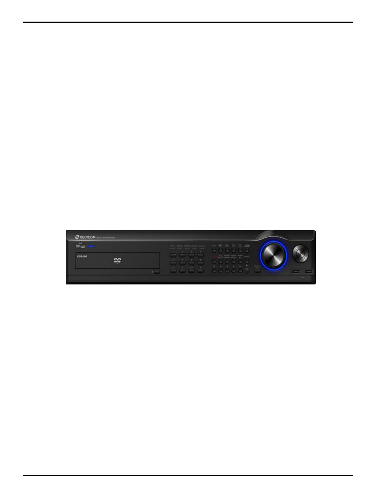
Kodicom KSR-916 User manual

USER GUIDE
DIGITAL
RECORDING SYSTEM
KSR-916
Please read this manual thoroughly before use, and
keep it handy for future reference.

2
2
KSR
KSR-
-916 Manual
916 Manual
This manual is published by KODICOM Co, Ltd and contains
information on KSR-916 which will enable you to use this product
properly.
If you require additional copies of this manual, please print the
manual contained in the CD provided with your purchase.

KODICOM
KODICOM 3
3
Introduction
Introduction
Introduction
Thank you for purchasing KODICOM KSR-916.
This DVR is produced by the most advanced KODICOM technology and its quality
is guaranteed by strict reliability and compatibility testing.
This KSR-916 manual provides necessary information for the correct use of this
product and also contains some useful tips.
Please read this manual thoroughly before using your KSR-916 in order to prevent
possible breakdown due to any mishandling.

KODICOM
KODICOM 4
4
This manual applies to KSR-916 DVR only.
This manual describes external features of the KSR-916 DVR, part names, correct
connection methods for supported domes or Pan/Tilt receivers, control devices,
peripheral devices, and the system set up instructions. It should be noted that
some features, figures, pictures and references can only be applied to one model
either KSR-916.
• KODICOM can not be held responsible if the DVR is damaged due to non-
compatible devices being used with this product. If you have any doubts please
check.
• KODICOM can not be held responsible if the DVR is damaged due to the product
being disassembled or modified by the user.
• If you wish to open the system casing to attempt to modify, repair, or upgrade the
system, it is recommended that you ask for a KODICOM engineer’s assistance by
contacting either your dealer or KODICOM head office.
• This product is qualified for both domestic and industrial use. This product is
qualified under the Radio Equipment Requirements of Korea and acquired
international certification including CE (Europe) and FCC (USA).
Notice
Notice
Notice

KODICOM
KODICOM 5
5
All copyrights of this manual are reserved by KODICOM CO., Ltd.
Copyright© 2009
It is prohibited to copy or republish this manual for commercial reasons.
It is prohibited to transfer this manual via online media such as, but not limited to,
the Internet. It is also prohibited to post, distribute, or translate this manual without
KODICOM’S permission.
KODICOM is not held responsible if the DVR is damaged due to the system being
handled inappropriately by a user who is not aware of how to operate this product,
or by a user who did not refer to this manual before attempting to operate the
product.
KODICOM reserves the right to change the contents of this manual without notice.
KODICOM reserves all copyrights of registered trademarks in this manual.
Copyrights
Copyrights
Copyrights

KODICOM
KODICOM 6
6
Caution
Caution
Caution
Please be aware of the following precautions before installing the DVR.
• Avoid positioning the KSR-916 in any place where the unit may come into contact
with moisture, dust, or soot.
•Avoid placing in direct sunlight or near heating appliances.
•Keep the product away from electric shock or magnetic substances.
•Avoid temperature extremes (recommended operation temperature is between
0°C and ~40°C).
•Do not place any conductive material through the ventilation grills.
•Keep the system turned off before installation.
•Ensure enough space is left for cable connections.
•Place the system on a solid surface with sufficient air ventilation. Avoid any
surface that vibrates.
•Placing the system near electronic devices such as radio or TV may cause
breakdown to the product.
•Do not disassemble the product without seeking assistance from KODICOM.
•Do not place any heavy object on the system.

KODICOM
KODICOM 7
7
The following are warnings and cautions for the safety of the users and for
the prevention of any property damage. Please read below thoroughly.
Warning and Caution signs
If you are not aware of this
warning, you may be seriously
injured or be killed.
If you are not aware of this
caution, you may be injured
or cause property loss.
Warning Caution
Safety Warnings and Cautions
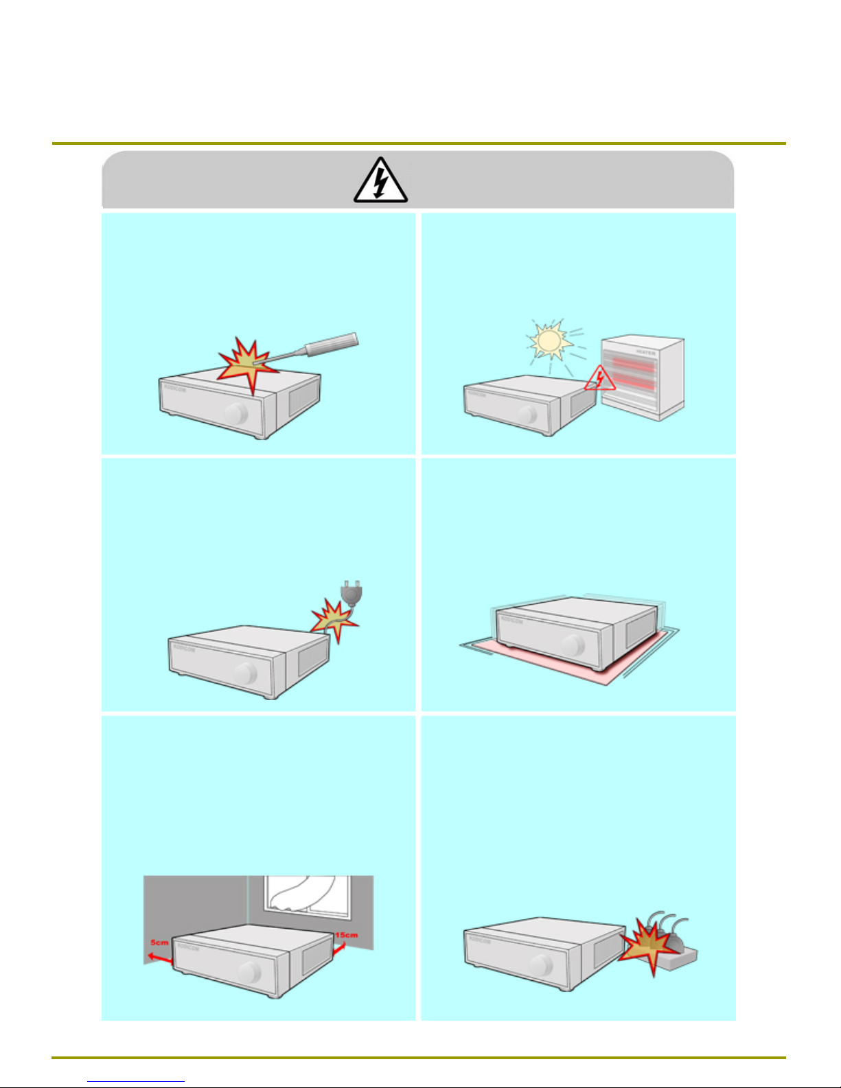
Turn off the system before installing the system.
Do not plug in several electric devices to the
same outlet.
yThis may cause heating, fire, or electric shock.
Do not place any liquid container on the system,
such as water, coffee, or beverage.
• If liquid is poured onto the system, it can cause
a system breakdown or cause fire.
Prevent power cable from being severely bent or
pressed by a heavy object.
•This may cause fire.
Clean the dust around the system on regular
basis. When cleaning the system, always use dry
cloth. Do not use wet cloth or other organic
solvents.
• This may damage the surface of the system and
can cause system breakdown or electric shock.
Avoid any place with moisture, dust, or soot.
•This can cause fire or electric shock. When pulling the power cable from the plug, do
so gently. Do not touch the plug with wet hands
and avoid using the plug if the holes on the outlet
are too loose.
•This may cause fire or electric shock.
Warning

KODICOM
KODICOM 8
8
Do not attempt to disassemble, repair, or modify
the system on your own. It is extremely dangerous
due to high voltage running through the system.
• This may cause fire, electric shock, or serious
injuries.
Install the system in a cool place without direct
sunlight and always maintain room temperature.
Avoid candle light and heat-generating devices
such as heater. Keep the system away from
places where many people pass.
•This may cause fire.
Check for any danger signs such as moist floor,
loosened or damaged power cable, or unstable
surface. If you encounter any problems, ask for
assistance from your dealer.
•This may cause fire or electric shock.
Install the system on a plain surface with sufficient
air ventilation. Do not place the system on
elevated surface.
• This may cause system breakdown or serious
injuries.
Keep at least 15cm between the back of the
system and a wall for the cables connected into
the system. Otherwise, cables may be bent,
damaged, or cut.
•This may cause fire, electric shock, or injuries.
The power outlet must be placed on a ground,
and the voltage range must be within 10% of the
voltage rate. Do not use the same outlet with a
hair dryer, iron, refrigerator, or any heating
appliances.
•This may cause fire, heating, an electric shock.
Warning

KODICOM
KODICOM 9
9
When the system’s battery is depleted, you must
change it with the same or equivalent type of
battery specified by the manufacturer. Depleted
batteries should be discarded according to
manufacturer’s instructions.
•This may cause an explosion.
If the system’s HDD has exceeded its life span,
you may not be able to recover any data stored
inside the HDD. If the video on the system screen
appears ‘damaged’ while playing a recording
stored inside the system’s HDD, it must be
replaced with a new one. Ask for an engineer’s
assistance for HDD replacement from your dealer.
• KODICOM is not responsible for deleted data
caused by user’s mishandling.
Warning
CALIFORINIA USA ONLY
This Perchlorate warning applies only to primary CR
(Manganese Dioxide) Lithium coin cells in the
product sold or distributed ONLY in California USA.
“Perchlorate Material - special handing may apply,
See www.dtsc.ca.gov/hazardouswaste/perchlorate.”
Turkey ONLY
“This EEE is compliant with ROHS”

KODICOM
KODICOM 10
10
Do not install the system in a place with high
magnetic, electric wave, or wireless devices such
as radio or TV.
• Install the system in a place without magnetic
objects, electric frequencies, or vibration.
Install the system in a place with appropriate
moisture and temperature level.
• Avoid installing the system with high (over 40℃)
or low (under 0℃) temperature.
Prevent any substances from being inserted into
the system.
•This may cause system breakdown.
Do not place any heavy object on the system.
•This may cause system breakdown.
Install the system in a place with sufficient air
ventilation.
• Keep at least 15cm distance between the back
of the system and a wall, and at least 5cm
distance between the side of the system and a
wall.
Install the system on a stable and leveled surface..
•The system may not operate properly.
Caution

KODICOM
KODICOM 11
11
The system can be damaged from a strong impact
or vibration. Avoid throwing objects within the
vicinity of the system.
The outlet must be placed on the ground.
Avoid direct sunlight or any heating appliances. If there is strange sound or smell, unplug the
power cable immediately and contact the service
Center.
•This may cause fire or electric shock.
Ventilate the air inside the system operation room,
and tighten the system cover firmly.
• System breakdown may be cause by
inappropriate environment.
In order to maintain stable system performance,
have your system checked regularly by the
service Center.
• KODICOM is not held responsible for system
breakdown caused by user’s mishandling.
It is recommended to use AVR (Automatic Voltage
Regulator) for stable power supply.
It is recommended to coil the core-ferrite around
the connector of the system to avoid
electromagnetic interference.
Caution
Do not overturn the product under use.

KODICOM
KODICOM 12
12
Equipment
Equipment
Equipment
Please check to make sure the following equipment are included when you
purchased DVR. If any items are missing, contact your dealer.
(The user manual will be included either inside the product software CD or a quick
Manual including important contents.)
Battery
Bracket Rack
Audio Cable
(Extra)
Mouse
SATA Cable
RS-485 Connecter
CD
(Manual/Software)
Manual (Site/Center) Remote Controller
Power Cable
Screws

KODICOM
KODICOM 13
13
Contents
Contents
Contents
Chapter 1. Introducing your real time DVR
Chapter 2. Installation
2.1 Checking install environment……………………………………………………………………………………26
2.2 USB Connection……………………………………………………………………………………………....………29
2.3 CONSOLE Controller……………………….…………………………………………………………………………31
2.4 Connecting NETWORK Communication Lines………………………………………………….……………32
2.4.1 Network and Dedicated Line Connection…………………………..…………………………………32
2.4.2 PSTN (telephone line) Connection (optional)………………………………………………………33
2.5 Alarm-In Port Connection (Input)………………………………………...…………………………………34
2.6 Alarm-Out Port Connection (Output)………………………………………..…………………………………35
1.1 Front Panel………………………………………..……………………………………………………………………17
1.2 Rear Panel…………………………………………………..……………………………………………………20
1.3 Description of the Remote Controller…......……………………………………………………………………24
3.1 Screen layout ……………………………………………...………………………………………………………37
3.2 POP-UP MENU……………….…………………….………………………………………………………………38
3.3 Live screen mode…………………………..………………………………………………………………………40
3.4 1ch Playback…………………………………………..………………………………………………………………42
3.5 Pan/Tilt Camera…………………………..…………………………………………………………………………43
3.5.1 Switching to Pan/Tilt control mode………………………………………….…………………………………43
3.5.2 Pan/Tilt Camera Control………………….………………………………….…………………………………44
3.5.3 Supported Pan/Tilt Camera List………………….……………………….…………………………………45
3.6 ALARM OUT – Manual Control……………………………………………………………..…………………46
3.6.1 Switching to Alarm Out mode……………………….…..………………………………………………………46
Chapter 3. Live
4.1 User Login……………………………………………………………………………………………………………48
4.2 Recording menu…………………………………………….……………………………………………………48
4.2.1 Motion detection……………………………………..…………………..…………………………………49
4.2.2 Schedule………………………………………..…………………………………………………………51
4.2.3 Quality/Resolution………………………….………………………..…………………………………53
4.2.3.1 Normal REC Setting……….………………………..…………………..…………………………………53
4.2.3.2 Alarm REC Setting…………….………………..…………………………………………………………54
4.2.3.3 Network REC Setting……………..……………..…………………………………………………………55
4.2.3.4 Alarm REC Time…………………….…………..…………………………………………………………56
4.2.4 Property………….…………..…………..…………….………………………..…………………………………57
4.3 Camera menu…………………………………………….……………………………………………………58
4.3.1 Channel Setting…………………………...………………..…………………..…………………………………58
4.3.2 Alarm In Setting………………………………………..…………………………………………………………59
4.3.3 Relay Out Setting………..………………………….………………………..…………………………………60
4.3.3.1 Alarm In/Relay Out Link……….………………………..……………..…………………………………61
4.3.3.2 Motion/Relay Out Link…………….…………..…………………………………………………………61
4.3.3.3 System Error/Relay Out Link…….……………..…………………………………………………………61
4.3.4 Alarm In Camera link……………………………..…………………………………………………………62
4.3.5 Spot Out Camera link………..…..….………….………………………..…………………………………62
Chapter 4. System setup

KODICOM
KODICOM 14
14
4.4 Network…………………………………………….……………………………………………………64
4.4.1 DDNS Setup…………………………...………………..…………………..…………………………………64
4.4.2 Network Setup………………………………………..…………………………………………………………65
4.4.3 Network Test………..…..…………….…………….………………………..…………………………………67
4.4.4 Network Time Setup………………………………………..…..………………………………………………67
4.4.5 Emergency Notification………..…..……………….………………………..…………………………………70
4.5 System Setup…………………………………………….……………………………………………………75
4.5.1 User Management………………………………………..…………………..…………………………………75
4.5.1.1 Password Setup………………..………………………..………………………………..…………………76
4.5.1.2 User Addition Setup…………………………………….………………………………..…………….……76
4.5.1.3 Group Setup …………..............………………………..………………………………..…………………77
4.5.2 Site Setup………………………………………..……..………………………………………………………78
4.5.2.1 Regional Setting………………..……………………..………………………………..…………………78
4.5.2.2 OSD Dwell Time…………………………………….………………………………..…………….……79
4.5.2.3 Remote Control ID …………..............……………..………………………………..…………………81
4.5.2.4 Beep Setup..…………………………………………..………………………………..…………………81
4.5.2.5 Live Audio..…………………………………………….………………………………..…………………82
4.5.2.6 Serial Port..…………………………………………..………………………………..…………………82
4.5.2.7 PIP Setting..…………………………………………….………………………………..…………………83
4.5.2.8 Monitor..…………………..…………………………….………………………………..…………………84
4.5.3 Software Upgrade………..…..…….…………….………………………..…………………………………85
4.5.4 Schedule…………………………………..…..…………………………………………………………..…86
4.5.4.1 Backup Schedule……………..………………………..………………………………..…………………86
4.5.4.2 System Restart………..…..………………………..……………………..…………………………………87
4.5.5 Storage………………………………..………………..…………………………………………………………88
4.5.5.1 External Storages………………………………..………………………………..…………………...88
4.5.5.2 Hard Management…………………..…………….……………………………..…...………….……….89
4.5.5.3 RAID Management………………..…………….………………………………..…...………….……….91
4.5.6 POS Management…………………..………..…………………………………………………………91
4.5.6.1 Data Format Setting……………………………..…….……………………………..…………………….. 91
4.5.6.2 DATABASE Setting……………………..…………….…………………………..…...………….…………93
4.5.6.3 POS Configuration ………………..…………….………………………………..…...………….…………94
4.6 System Info………………………………………….………..………………..………………………………………95
4.6.1 Log Info……………..…………………………………..………………………………..………………………95
4.6.2 Factory Default………….…….…..………..…………………………………………..…………….………...98
4.6.3 System Shutdown/Restart ……….....................…………………………..……………..………………..…98

KODICOM
KODICOM 15
15
Appendix
1. KDB Viewer……………………………………………………………………….……………………………………112
1.1 How to run Viewer………………………………..……………….…………..…………………………………112
1.2 Viewer main screen……………………………………………....……………………………………………113
2. WebDVR………………..………………………………………………………………………………………………115
3. Watermark Checker………………………………………….………………………………………………………120
4. CMS Software…………………………………………………………………………………………………………122
5. Specifications…………………………………………………………………………………………………………135
6. FAQ………………………………………………………………………………………………………………137
6.1 Video Backup ……………………………………………………………………………………..……………108
6.2 Still Image Backup………………………..………………………………………………………..…………109
6.3 Media Format…………………….……………..………………………………………………..…………110
Chapter 6. Backup
5.1 Accessing Search Mode ………………………………………………………………………………………100
5.2 Search mode display………………………..………………………………………………………………100
5.3 Selecting date and time …………………………..………………………………………………………101
5.4 Selecting cameras and changing search bar line……….…………………………………………102
5.5 Audio Output………………………………………………………………………..…………………103
5.6 Playback………………………..……………………………………………………………………104
5.7 Event Search………………………..………………………………………………………………105
5.8 POS …………………………………………………………………………………………………….106
Chapter 5. Search

16
16
1. Introducing your real
time DVR
time DVR

17
17
The following describes the keys and ports on the front of the system and their functions:
[Power]
•Use this button to shutdown the DVR.
• When the button is pressed a password menu will pop-up and password details should be
entered click [OK] and the DVR will turn off.
[Shuttle (outer dial)]
•Rotate to play the recordings, in Search mode, forward or backward.
•Rotate to change the value of options continuously in Setup mode.
•When controlling P/T/Z camera. rotate to zoom in or out.
[Jog (Inner dial)]
•Rotate to view recordings, in Search mode, forwards or backwards one frame at a time.
Rotate to change the value of options one unit at a time in Setup mode.
When controlling P/T/Z camera, rotate to shift camera lens focus.
[HOLD]
• When using the Shuttle dial you can press the [HOLD] button to maintain the present shuttle
speed.
•Press the [HOLD] button again to deactivate the feature.
[Enter Key]
• Use to select option in Setup or Search mode. Use to directly go to Control setup mode from
the Surveillance mode.
1
2
[System front view(KSR-916)]
3
4
5
1.1 Front panel
1.1 Front panel
4
712 13
15
17 18
9
86
2
13
10 11
14
16 5

18
18
6
7
8
9
10
[Directional keys]
•Use to move through the menu options in Setup or Search mode.
•When controlling P/T/Z camera, press the directional keys to move the camera.
•When searching recorded image, you can adjust the size of the image using up and down directional key.
[Camera/Number keys]
•In Surveillance mode, press for full screen display of that camera.
•In Search mode, press for full screen display of that camera recording during playback.
•Press the keys enter correct numeric password when accessing Setup or Search modes.
[AUTO]
•Press [AUTO] to begin automatic channel sequence in full screen mode.
•Press [AUTO] button again begin cancel the automatic channel sequence in full screen mode.
[Split screen buttons]
•On Surveillance or Search modes, press to select 4-splitscreen, 9-splitscreen or 16-split screen.
•Press repeat the splits button, can show the splits screen for other channel.
[KEY LOCK]
•The [KEY LOCK] button can be used lock the buttons on the front of the DVR system.
• When activating and deactivating the key lock function a password menu will pop-up and password
details should be entered to switch between modes.
[MENU]
•To go to the system configuration window, press the [MENU] button. You will then be
asked to enter the user ID and password. To exit the current menu or to close the
configuration window, press [MENU] button.
[EMERGENCY]
•Use the [EMERGENCY] button to transmit video data to a remote location in the case of emergency.
[A/V SELECT]
•The [A/V SELECT] Button can be used to select and hear audio in the surveillance screen mode.
•Press [A/V SELECT] button to activate the live audio select mode then press the Channel
button you wish to listen.
•To change the video mode from audio mode, press [A/V SELECT] button again.
11
12
[Note] OSD Position Control Function
•It is possible to control OSD position by Up/Down/Left/Right button on 16 division screen.
☞
☞
13

19
19
[REVERSE PLAYBACK]
•USB the [SEARCH] button to playback a selected channel in surveillance
mode.
[INSTANT BACKUP]
•The [INSTANT ACKUP] button once pressed automatically makes a back-up of all channels
for the 5 minutes prior to the button being pressed to the USB port.
[INSTANT REC]
•In the case of an emergency or an emergency night happen press the [INSTANT REC] button.
• Use the [INSTANT REC] button to record video data from all cameras regardless of the
recording schedule.
[SEARCH]
•To go to the search window, press the [SEARCH] button. You will then be asked to enter the
ID and password.
•Used to move of before menu or other menu.
[Search mode control Keys]
•In Search mode, use these keys to view the recording from either the first or last recorded
image, to play the recording either forwards or backwards, and pause the recording.
[LED Status Panel]
-The LED Status Panel displays the current operation state of the DVR.
REC : The light indicates that the DVR is recording.
BACKUP : The light indicates when a backup is in progress.
NETWORK : The light indicates that a client is connected remotely.
AUDIO SEL : The light indicates when the audio select function is active.
KEYLOCK : The light indicates when the key lock function is active.
[CD/DVD-RW]
•The CD-RW/DVD-RW is used to backup video data.
[USB Port]
•You can connect a portable disk drive to USB port to save backup of recorded video.
•You can update your system software with an upgrade package through the USB port.
•You can control screen menu with connecting USB type mouse.
14
15
16
17
18

20
20
The following describes keys and ports on the rear part of the system and their functions.
[System rear view(KSR-916)]
[Power Connector]
•Power cable input, 100V ~ 240V, for system main power supply.
1
2
3
[Caution]
•Be careful of electrocution. Please read [Safety Warnings and Cautions].
[Camera Video Input BNC]
•Connecting cameras to DVR, input the video signal coaxial cable to the BNC input on the DVR.
[Loop Through Output]
•Video output ports for camera loop through to view images on another monitor or device.
•The system supports both NTSC and PAL.
[V-Output Port]
•Video output for connecting with CVBS monitor.
[SPOT Monitor Output]
•Spot monitor output for video output connection to a external Spot monitor.
[Caution]
• Dependant on the grounding status of the power supply electric current that can cause an
electric shock may flow in the video line (coaxial cable). Turn off the system before
connecting the video line to the BNC port.
4
5
1.2 Rear panel
1.2 Rear panel
1
23
13
45
12
11 15 16
891410 7 617
Table of contents
Other Kodicom DVR manuals