Cotton swab
Inside of the ionized air outlet
POWER
ALARM
HV
FLOW
1
2
3
HIGHLOW
.
●How to Connect to Wiring for Power Supply and Abnormal Output Contracts
(1) Connect the supplied the Power Supply Signal Cable to the connector on the
backside of the main unit.
(2) Connect the + 24 V line of the DC power supply to the "red" line, and 0 V line to the
"green" line of the Power Supply Signal Cable, respectively.
(3) If the Abnormal Output Contacts are to be used, connect the Contact to the “White”
and “Black” lines of the Power Signal Cable. No polarity is involved with the
connections in this case.
Caution
Make sure that the connections are carried out in a secure manner by using a terminal
block or crimp-style terminals, etc. Otherwise, main unit gets damaged.
If the abnormal output circuits are to be used, make sure the circuits are used within
the rated specification range (24 VDC; 50 mA, max.). Otherwise, the main unit may
possibly be damaged.
See the diagram below for the abnormal output circuits.
The abnormal output circuits will start working about 2 seconds after the power is
turned on. Pay special attention when designing the abnormal detection circuits to be
incorporated in the system.
If no abnormal output circuits are to be used, be sure to carry out some appropriate
measures for insulating the "white" and "black" tail ends of the supplied Power Supply
Signal Cable. Otherwise, main unit gets damaged.
●How to Ground the Wiring
(1) Connect the round terminal of the supplied Grounding Lead Wire to the grounding
terminal located on the backside of the main unit.
(2) Connect the terminal at the opposite end of the Grounding Lead Wire to the
grounding point.
Caution
0V line and grounding terminal are connected common line in main unit.
Warning
Confirm that the grounding point is properly grounded. If it is not, be sure to carry out
the grounding procedure (according to the 3rd class procedure).
The product must be properly grounded. Otherwise, an electric shock accident or a
malfunction of the unit may occur. In addition, the product may not be able to work up
to the full performance.
6. Operation
6.1 Operations When Turning ON the Power
(1) Check the product to confirm that the setting and wiring have been carried out in
accordance with the instructions given under Section 5. "Installation/Wiring" in this
manual.
(2) Turn ON the switch on the DC power supply.
(3) Press once the power switch (push-button type) located on the front of the product.
The power will be supplied to the product. If the unit is operating normally, both the
power switch and high-voltage power supply LED (green) located on the front side of
the product will light up.
(4) In accordance with the distance to the charged object and the amount of static
electricity charged on the object, adjust the Airflow Adjustment Knob to provide the
appropriate amount of airflow.
Caution
If the Power Switch of the unit or the high-voltage LED does not light up, or if the alarm
display on the front of the unit lights up, immediately turn off the power from the unit.
Then, check the installation and wiring against the instructions given under Section 5.
"Installation/Wiring." In case you cannot solve the problem even then, please refer to
Section 7. "Maintenance" and Section 8. "Troubleshooting."
6.2 Operations When Turning OFF the Power
(1) Press once the Power Switch (push-but the type) located on the front of the product.
Both the Power Switch and their high-voltage LED on the front of the product will go
off.
7. Maintenance
Warning
Maintenance is an extremely important factor for achieving the optimum performance
of the device. Be sure to carry out the maintenance work on a regular basis.
Before you perform the maintenance work, make sure that the Power Supply Signal
Cable has been disconnected.
When you are using solvent such as alcohol, make sure that the room is well
ventilated. And if you have used alcohol for cleaning, make sure that all alcohol has
evaporated and no part on the main unit is wet with alcohol.
The tip of the Discharge Needle is pointed. When removing or cleaning the Discharge
Needle Unit, pay special attention to the Discharge Needle Unit, or else you may injure
yourself. Be careful not to cause the Discharge Needle to be bent or broken, otherwise,
the performance of the unit may be greatly degraded.
7.1How to Clean the Discharge Needle
The material used for the Discharge Needle of this product is tungsten. Tungsten as the
material for Discharge Needles is very durable and will not wear off easily. If the product
is regularly maintained in a normal manner, almost no degradation of the performance
will be observed.
●If the Discharge Needle Unit is not to be removed:
(1) Confirm that the cable is not connected to the connector on the Backside of the main
unit. If connected, disconnect the cable.
(2) Soak the supplied Discharge Needle Cleaning Brush in anhydrous alcohol such as
isopropyl alcohol. Use the brush to remove the foreign particles attached to the tip of
the Discharge Needle.
(3) If the inside of the ionised air outlet is soiled, moisten a cotton swab with anhydrous
alcohol such as isopropyl alcohol and wipe off the soiled surfaces with the swab.
Note that cotton swabs are not supplied with a main unit as an accessory item.
Please prepare them by yourself when using them.
Caution
If cleaning of the Discharge Needle is to be carried out without removing the Discharge
Needle Unit, it is possible that dust may be splashed when the unit is operated after the
cleaning work is completed due to the lack of cleaning of the backside of the Discharge
Needle and to falling of dust into the internal part of the main unit. It is recommended,
therefore, that you perform the cleaning work by removing the Discharge Needle Unit.
●If the Discharge Needle Unit is to be removed:
(1) Confirm that the cable is not connected to the connector on the Backside of the main
unit. If connected, disconnect the cable.
(2) In accordance with 7.2 “How to Replace the Discharge Needle Unit,” remove the
Discharge Needle Unit.
(3) Soak the supplied Discharge Needle Cleaning Brush in anhydrous alcohol such as
isopropyl alcohol. Use the brush to remove the foreign articles attached to the tip of
the Discharge Needle.
(4) If the board of the Discharge Needle Unit is soiled, moisten a piece of waste cloth
with anhydrous alcohol such as isopropyl alcohol and wipe off the soiled surfaces
with the cloth.
(5) In accordance with 7.2 “How to Replace the Discharge Needle Unit,” install the
Discharge Needle Unit.
Caution
The tip of the Discharge Needle is sharply pointed. Pay special attention to handling of
the Discharge Needle Unit after it is removed from the unit.
If the soil on the tip of the Discharge Needle cannot be removed by cleaning, or if the
Discharge Needle is bent or broken by an accident, etc., replace the Discharge Needle
Unit with new one in accordance with 7.2 "How to Replace the Discharge Needle Unit."
If you continue to use the unit without replacing the defective needle, the performance
may be degraded or insufficient static elimination may occur.
7.2 How to Replace the Discharge Needle Unit (DTRY-ZEM-W23)
The material used for the Discharge Needle of this product is tungsten. Tungsten as the
material for Discharge Needles is very durable and will not wear off easily. If the product
is regularly maintained in a normal manner, almost no degradation of the performance
will be observed. In case, however, contamination cannot be removed due to negligence
of maintenance or the Discharge Needle is bent or damaged due to an accident, etc.,
replace the entire Discharge Needle Unit with a new one.
(1) Confirm that the cable is not connected to the connector on the backside of the main
unit. If connected, disconnect the cable.
(2) Unscrew the set screws (or the Knurl Screws) of the Discharge Needle Unit.
(3) While securely holding the Bracket section of the Discharge Needle Unit, pull it out in
a straight line.
Caution
The tip of the Discharge Needle Unit is sharply pointed. Pay special attention when
handling of the Discharge Needle Unit.
(4) Prepare a new Discharge Needle Unit.
(5) While securely holding down the main unit, insert the Discharge Needle Unit into the
plug-in inlet of the main unit until the Discharge Needle unit is securely locked in the
main unit.
Caution
When inserting the Discharge Needle Unit into the main unit, insert it through the slits
(black) provided at both ends of the plug-in inlet of the main unit.
Insert the Discharge Needle Unit into the main unit in a straight line without applying
excessive force, or else a malfunction of the unit may occur.
When inserting the Discharge Needle Unit into the main unit, be careful not to touch the
air outlet of the main unit at Discharge Needle.
(6) Tighten the set screws (or the Knurl Screws) of the Discharge Needle Unit to lock
the unit at the specified position.
Caution
Make sure that screws are fully tightened. A niece grew not fully tightened may cause
defective operations of the unit or may prevent the unit from operating up to the full
performance.
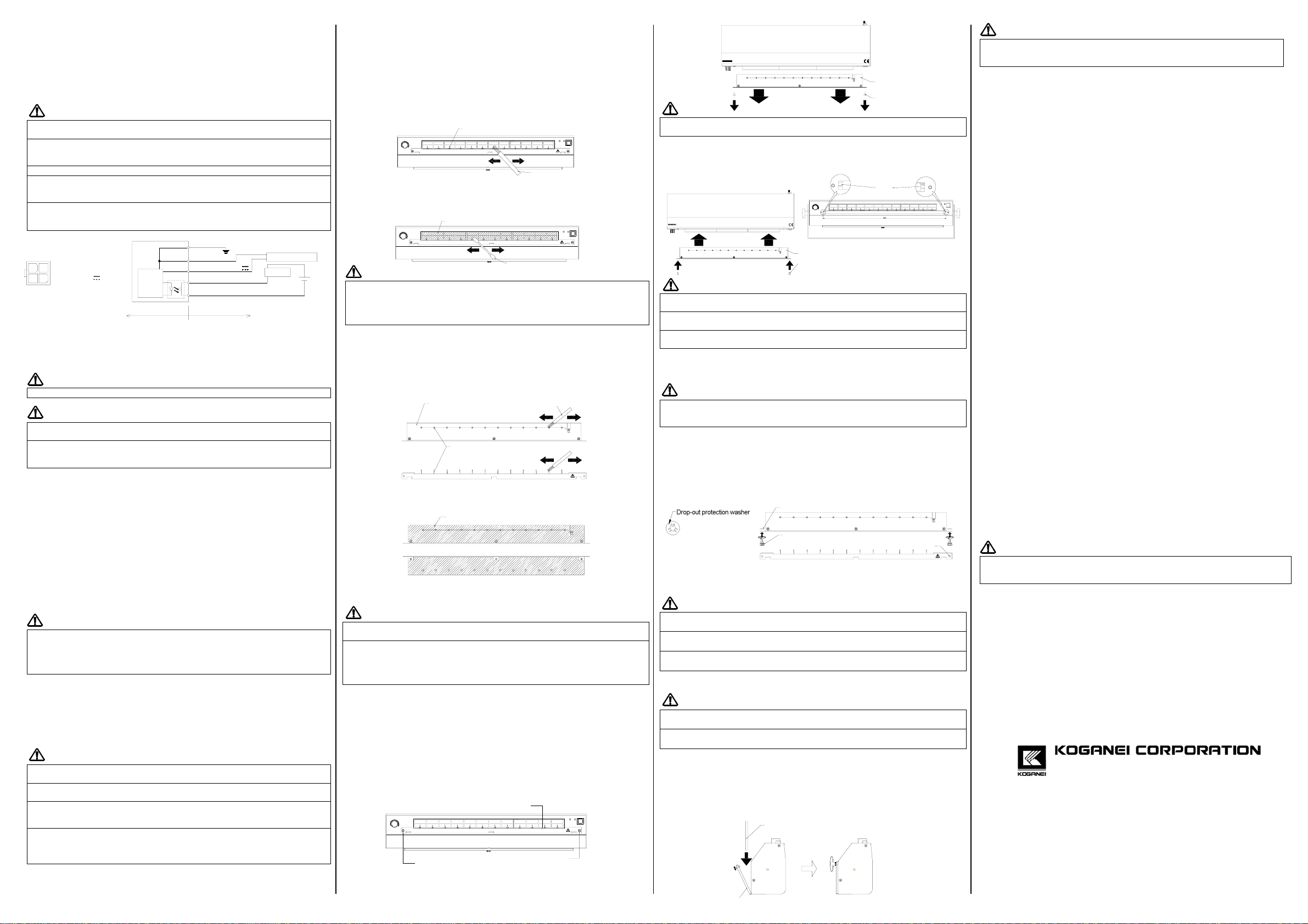
7.3 Discharge Needle Unit: How to Attach Knurl Screws
(1) Check the connectors on the back side of the main unit to confirm that no cable is
connected. If any cable is connected, disconnect it..
(2) Dismantle the Discharge Unit (DTRY-ZEM-W23) in accordance with the specified
method of replacement.
(3) Align a drop-out protection washer with each of the screwing positions for the
Discharge Unit and screw in a knurl screw on each of the 2 positions.
(4) Install the Discharge Unit (DTRY-ZEM-W23) in accordance with the specified
method of replacement.
Caution
The tip of the Discharge Needle is extremely sharp and pointed. Pay special
attention in working with the Discharge Needle Unit while it is being dismantled.
A Drop-out Protection Washer is a very small item. Be especially careful not to
misplace it.
When dismantling the Discharge Unit from the Main Unit, do not give a Knurl
Screw a strong pull, or else the Drop-out Protection Washer may come off.
7.4 How to Exchange the Filter (DTRY-ZFU-W23)
Caution
The Filter is a consumable item. When deterioration of the Filter is observed,
replace it with a new one.
When the Filter Cover is soiled or the Filter is clogged, the product cannot achieve
its full performance. Be sure to carry out regular maintenance.
(1) Confirm that the cable is not connected to the connector on the backside of the main
unit. If connected, disconnect the cable.
(2) In accordance with “How to Remove a Filter,” remove the Filter.
(3) Wipe off the soil from the Filter Cover using a piece of waste cloth soaked with
anhydrous alcohol such as isopropyl alcohol.
(4) Mount the newly prepared Filter in the Filter Cover.
(5) Close the Filter Cover and lock it on the main unit using Knurl Screws.
Caution
Make sure that the Knurl Screws are fully tightened. Any Knurl Screws not fully
tightened may cause the Filter Cover to be disengaged while the unit is used, or may
cause some noise to be generated.
7.5 Inspection
(1) Check the Power Supply Signal Cable to confirm that there is no deterioration or
breaking in the insulation.
(2) Check the power supply voltage and the width of its variation to ensure that they are
within the specified range.
(3) Check the main unit to confirm that there is no unknown noise generated from the
unit.
8. Troubleshooting
In case any abnormal condition is observed in this product, immediately turn of the power
from the main unit. Disconnect the cable from the connector on the backside or the main
unit. Then, read this section carefully and follow the instructions. If the abnormality cannot
be solved even after that, please contact the shop where you purchased the product (the
agency), or the nearest service station of our company.
○Symptom:
• The power cannot be supplied to the unit. (All indicators do not light up at all, and the
fan does not turn.)
●Contents to be confirmed:
• Check the DC power supply unit to confirm that the power is turned ON. If you are
using an AC adapter, check to see if the AC plug is securely inserted into the wall
outlet.
• Check the input voltage to confirm that it is within the specified range.
• Check the Power Signal Cable to confirm that the wire is not broken.
• Check the Power Signal Cable to confirm that the wiring has been correctly
performed.
• Check the Discharge Needle Unit is installed in the correct manner.
○Symptom:
• The abnormality indications LED lights up.
●Contents to be confirmed:
• The Discharge Needle may be soiled or damaged. Carry out the maintenance work
for the Discharge Needle Unit in accordance with the instructions given under
Section 7 “Maintenance.”
• Check the Discharge Needle Unit to confirm that the unit has been securely installed.
○Symptom:
• No static elimination is performed.
●Contents to be confirmed:
• The Discharge Needle may be soiled or damaged. Carry out the maintenance work
for the Discharge Needle Unit or replace the unit with a new one in accordance with
the instructions given under Section 7 “Maintenance.”
○Symptom:
• The abnormal output circuit is not working.
●Contents to be confirmed:
• Carry out the setting of the NO (contact a)/NC (contact b) contact selector switch
once again in accordance with 5.1 “Setting of Contacts for Abnormal Output” in this
manual.
Caution
The abnormal output circuits will start working about 2 seconds after the power is turned
on. Pay special attention when designing the abnormal detection circuits when this
product is to be built into a system.
○Symptom:
• The Power Switch LED lights up but the High-voltage Power Supply Indicator LED
and the Abnormal Indicator LED do not light up.
• The Power Switch LED lights up but the fan does not turn.
●Contents to be confirmed:
• It is possible that the product is broken down. Please contact the shop where you
purchased the product (the agency), or the nearest service station of our company.
○Any other abnormal condition:
• If any other abnormal condition than above has been observed, immediately turn
OFF the power from the product, and please contact the shop where you purchased
the product (the agency), or the nearest service station of our company
JUST CONSULT US
KOGANEI CORPORATION
OVERSEAS DEPARTMENT
3-11-18 Midori-cho, Koganei-shi Tokyo 181-8533, JAPAN
TEL: 042-383-7271 FAX:042-383-7276
Internet Home Page URL: http://www.koganei.co.jp
zPlease understand that the appearance and the specifications of this Product may be
altered without advance notice for improvements.
Ver.1.00
Discharge
needle(12pieces)
Discharge
needle unit
Discharge needle
cleaning brush
Parts to be cleaned
Front side of the Discharge needle unit
Back side of the Discharge needle unit
DTRY-ELW23
Discharge
needle unit
Discharge needle
unit set screw
DTRY-ELW23
Discharge needle
unit set screw
Discharge
needle unit
POWER
ALARMHV
FLOW
1
2
3
HIGHLOW
.
Slits
(Both ends)
Screw position(2locations)
Drop-out protection washer(2locations)
Dischage needle (12 pieces)
Discharge needle
cleaning brush
POWER
ALARM
HV
FLOW
1
2
3
HIGHLOW
.
Knurl screw(2locations)
Bracket of discharge needle unit
POWER
ALARMHV
FLOW
1
2
3
HIGHLOW
.
Discharge needle unit set screw
Discharge needle unit set screw
Filter
Filter cover
4
3
2
1
4(Green):0V
3(Red DC
2(Black)
1(Whit
MainunitConnectorNumber
):+24V
:ALARM
e):ALARM
Main
Circuit 1(White):ALARM
2(Black):ALARM
3(Red):+24VDC
4(Green):0V DCPower;+24VDC
LOAD DC24V
InternalCircuits ExternalCircuits
MAXDC24V
50mA
GroundingTerminal


