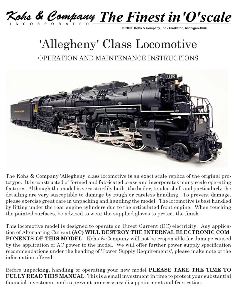
Kohs & Company New York Central J3a Hudson Manual

The Kohs & Company New York Central J3a 'Hudson' locomotive is an exact scale replica of the
original prototype. It is constructed of formed and fabricated brass and incorporates many scale
operational features. Although the model is very sturdily built, the boiler, tender shell and par-
ticularly the detailing are very susceptible to damage by rough or careless handling. To prevent
damage, please exercise great care in unpacking and handling the model. The locomotive is best
handled by lifting under the pilot 'horns' and rear cab deck. When touching the painted
surfaces be advised to wear the supplied gloves to protect the finish.
This locomotive model is designed to operate on Direct Current (DC) electricity. Any application
of Alternating Current (AC) WILL DESTROY THE INTERNAL ELECTRONIC COMPO-
NENTS OF THIS MODEL. Kohs & Company will not be responsible for damage caused by the
application of AC power to the model. We will offer further power supply specifications under
the heading of 'Power Supply Requirements', please make note of these recommendations.
Before unpacking, handling or operating this model PLEASE TAKE THE TIME TO FULLY
READ THIS MANUAL. This is a small investment in time to protect your substantial financial
investment and to prevent unnecessary disappointment and frustration.
OPERATION AND MAINTENANCE INSTRUCTIONS
New York Central J3a 'Hudson'
©1998 Kohs & Company, Inc - Clarkston, Michigan 48348

PREPARING THE LOCOMOTIVE FOR OPERATION
Although your 'Hudson' is ready to operate, a few preventive maintenance steps should be taken to ensure
the smooth operation and longevity of the model. The locomotive has been lightly lubricated during assem-
bly and testing, while this will suffice for initial operation and break-in, you may wish to further lubricate
the side rod assemblies by applying 1 or 2 drops of good quality fine oil to areas where moving parts are in
contact with each other (refer to figure #1).
Your local hobby dealer should be able to
guide you in the selection of a suitable lu-
bricant. Care must be taken to avoid soil-
ing the surface of the sound cams located
on the rear-most drive axle (see figure #2).
Should this occur you will notice an alter-
ation of the cuffing pattern heard during
the operation of the locomotive. This situ-
ation can be corrected by carefully remov-
ing the lubricant using a cotton swab and
alcohol.
LOCOMOTIVE AND TENDER CONNECTIONS
The J3a 'Hudson' locomotive and tender require that two pair of connectors be joined to allow the opera-
tion of the model. The locomotive will not operate without the tender connected. The connections are
made by matching the shape of the connectors and firmly pressing them together while holding them by the
black housings (it is not possible to incorrectly make these connections). With the connection made, the
excess wire may be carefully pushed into the locomotive and tender. When disconnecting the locomotive
from the tender, pull only on the housings - Do Not Pull On The Wires! It is advised that the wire
connections be made with the locomotive and tender in place on the track, do not attempt to move the pair
while connected together.
The stoker feed tube should be positioned inside the stoker feed-ramp receptacle under the cab when join-
ing the locomotive and tender. The feed-ramp will swivel from side to side during operation to prevent
binding. The rear cab deck apron should rest on the front edge of the tender deck when you are ready to
operate. The drawbar has two coupling holes, the one closet to the end of the drawbar being for normal
operation and the one closest to the cab being for close-coupled operation. The ability to operate in the
close-coupled manor will depend on your operating radius. The locomotive and tender may be close-coupled
when running on a radius of 72" or greater and for display purposes. When operating on a smaller radius,
you must use the coupling hole at the end of the draw bar to move the loco and tender further apart. When
making the draw bar connection, do not attempt to lift the tender on to the draw bar, instead you should use
a pair of tweezers to pull down on the draw bar, align it with the draw bar pin on the tender and then allow
it to spring up on the pin. You must have patience to properly connect the loco and tender, there are many
small detail items that may be otherwise damaged.
POWER SUPPLY REQUIREMENTS
The Kohs & Company 'Hudson' is a Direct Current (DC) electric scale locomotive. Do not attempt to use
AC power as damage will occur. The following criteria should be used when selecting your power
supply:
1) Direct Current (DC) which is filtered
2) 0-18 volts (DC)
3) Minimum available current should be approximately 8.0 amps
(figure #1)

PREPARING THE SOUND SYSTEM FOR OPERATION
The locomotive and tender contain a state-of-the-art sound system which digitally recreates actual locomo-
tive sounds including steam whistle, bell, blowers, compressors, emergency relief valve and cylinder ex-
haust chuff. While this sound unit requires track voltage to actuate certain sounds, the actual power used
to operate the sound system is supplied by two standard 9 volt batteries that are placed in the tender coal
bunker during operation of the locomotive, the batteries and wiring harness are packed in the box along
with the locomotive and tender. At the end of the wiring harness is a male plug which needs to be inserted
into the receptacle under the bearing box hatch cover on the floor of the bunker, with this connection made,
the coal load can be placed over the batteries to
conceal their installation. When you unplug the
batteries, do not pull on the wires, only the
plug shell.
NOTE: Your tender and sound control unit
come equipped with batteries. If you do
not plan to use your locomotive for an ex-
tended period of time it is highly recom-
mended that you remove these batteries.
The supplied sound system controller needs to
be wired in-line between your power supply and
the track in order to control the internal sound
system. There are four (4) screw terminals inside the control box which are labeled 'track' and 'cab'. To
allow easy access to these terminals, we left the upper and lower control-box shells unassembled. The
assembly screws and rubber feet are included inside the box for use after your connections have been made.
The tender was shipped to you with a scale 'tite-lock' style coupler installed for display purposes. For
operating and pulling consists you may replace the display coupler with the Kadee unit of your choice, the
holes are predrilled and tapped for the installation.
OPERATING THE LOCOMOTIVE
It is recommended that you operate the locomotive at a varying speeds and in both directions during the
break-in period, the break-in period should last for a total of approximately 60 minutes (this may be accom-
plished on an incremental basis). This will help the drive system to 'run-in' resulting in smoother running
characteristics.
You are now ready to put the locomotive into operation. To activate the sound system, locate the sound
system switch under the water tank hatch (see figure #3). Shortly after turning the system on you will
hear the blowers activate. With the locomotive stationary you will hear, in addition to the blowers, the air
compressors and pressure relief valves on an intermittent basis. When 'track' power is applied to the loco-
motive, the blowers will turn off and the brake release will sound. As soon as the drivers begin to turn, the
chuffing of the cylinder exhausts will start in independent synchronization with each set of drivers. When
the loco is brought to a stop, the blowers will again start up while the intermittent sounds continue. The
whistle may be sounded at any time, when the system is turned on. The bell may be activated by touching
the control button once to turn it on and again to turn it off.
(figure #2)
Should you choose to use a less expensive power supply or one which does not meet the above criteria,
undesirable operating characteristics may result as well as possible damage to the electronics used in the
model. If you have questions regarding your selection, do not hesitate to contact us for advise.

DYNAMIC ELECTRONIC BRAKE (optional)
The dynamic brake uses power from the sound system batteries located in the tender bunker,
these batteries must be installed and the switch turned on in order for the brake system to
function. To activate the brake, press the 'whistle' and 'bell' buttons on the sound control box
simultaneously, to deactivate the system press the buttons again. Make certain that you do not
operate the locomotive routinely with the brake engaged, this will cause unnecessary additional
wear and tear on the drive system in the locomotive. The brake system offers the final dimen-
sion in train control, use it together with the throttle for the ultimate in control on downgrades
and in emergency situations.
LOCOMOTIVE CARE AND MAINTENANCE
Routine maintenance consists of periodic lubrication as described under the heading 'Preparing For Opera-
tion' and replacement of the sound system batteries covered under the heading 'Sound System'. It is advis-
able to periodically check the tightness of the small fasteners used to assemble the side rods and other
detailing to make certain that parts will not be lost. If the model will not be operated for an extended period
of time, remove the batteries from the locomotive and sound controller.
SERVICE
The Kohs & Company J3a 'Hudson' comes with a limited lifetime warranty to the original owner. We will
repair any model requiring service as a result of normal use, but not abuse. All of our guidelines for opera-
tion must be followed including the use of a proper power supply, otherwise the warranty is voided. We will
not replace consumable items such as light bulbs and batteries as a matter of course, but will make such
items available to customers on a cost basis. If you have technical questions or questions regarding service,
please contact us directly:
Phone: 248-625-6396
Fax: 248-625-7994
Your 'Hudson' is also equipped with an electronic control for the re-
verse-gear mechanism. The system responds to the polarity of the
power reaching the model and not the movement of the model. During
operation take care not reverse the direction of the locomotive with-
out first bringing the model to a complete stop, this will protect the
reverse-gear mechanism and also the drive gears which could other-
wise be damaged. It is normal for the current draw to be considerably
NOTE: IF THE TENDER SOUND SYSTEM SWITCH IS LEFT
ON, THE BATTERIES WILL BE DRAINED OF POWER EVEN
IF ALL CONNECTIONS TO THE LOCOMOTIVE ARE NOT
COMPLETE.
higher (approx 2A higher) in reverse due to the reverse-gear actuator.
To improve the tractive effort of your J3a 'Hudson', we have included a removable ballast load that will add
approximately 1/2 pound of additional weight to your model. The ballast is in the form of a soft pouch
which can be placed in the smokebox of your model. The entire smokebox front is hinged, just as is the
prototype, which allows for easy access to this area. For display purposes, you may choose to leave the
ballast uninstalled to allow the display of the interior detail.
(figure #3)
Revision: 3/11/99
Table of contents
Other Kohs & Company Toy manuals

Kohs & Company
Kohs & Company Norfolk & Western Y6a Mallet Troubleshooting guide

Kohs & Company
Kohs & Company Pennsylvania K-4 "Pacific" Troubleshooting guide

Kohs & Company
Kohs & Company Allegheny Troubleshooting guide

Kohs & Company
Kohs & Company Pennsylvania Railroad GG-1 Locomotive Troubleshooting guide
Popular Toy manuals by other brands

GREAT PLANES
GREAT PLANES Super Sportster EP instruction manual

Fisher-Price
Fisher-Price 77455 instructions

Fisher-Price
Fisher-Price H8093 instructions

Real Good Toys
Real Good Toys Beachside Bungalow instructions

J-Power
J-Power Thunderbolt Mini A10 Assembly and operating instructions

REVELL
REVELL Bristol Beaufighter TF.X Assembly manual