Kohs & Company Norfolk & Western Y6a Mallet Troubleshooting guide

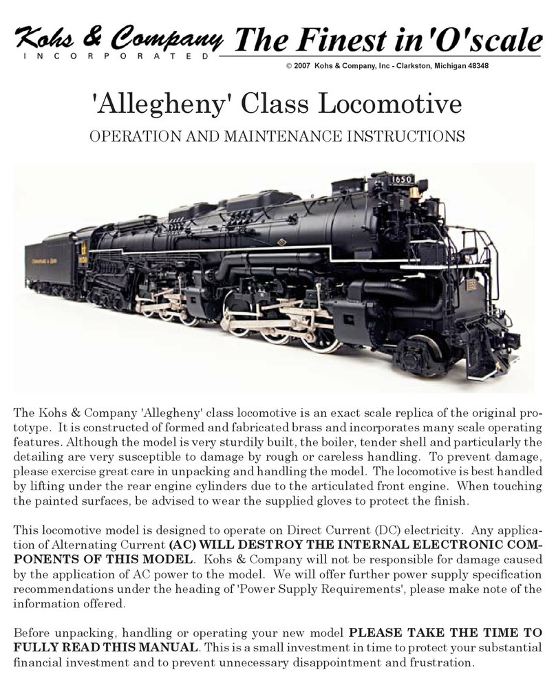
The Kohs & Company Norfolk & Western Y6a locomotive is an exact scale replica of the original
prototype. It is constructed of formed and fabricated brass and incorporates many scale operat-
ing features. Although the model is very sturdily built, the boiler, tender shell and particularly
the detailing are very susceptible to damage by rough or careless handling. To prevent damage,
please exercise great care in unpacking and handling the model. The locomotive is best handled
by lifting under the rear engine cylinders due to the articulated front engine. When touching
the painted surfaces, be advised to wear the supplied gloves to protect the nish.
This locomotive model is designed to operate on Direct Current (DC) electricity. Any applica-
tion of Alternating Current (AC) WILL DESTROY THE INTERNAL ELECTRONIC COM-
PONENTS OF THIS MODEL. Kohs & Company will not be responsible for damage caused
by the application of AC power to the model. We will offer further power supply specication
recommendations under the heading of 'Power Supply Requirements', please make note of the
information offered.
Before unpacking, handling or operating your new model PLEASE TAKE THE TIME TO FULLY
READ THIS MANUAL. This is a small investment in time to protect your substantial nancial
investment and to prevent unnecessary disappointment and frustration.
OPERATION AND MAINTENANCE INSTRUCTIONS
Norfolk & Western Y6a Mallet
© 2003 Kohs & Company, Inc - Clarkston, Michigan 48348

PREPARING THE LOCOMOTIVE FOR OPERATION
Although your Y6a is ready to operate, a couple preventive maintenance precautions should be
observed to ensure the smooth operation and longevity of the model. First of all, make certain
that all of the small fasteners used to assemble the running gear are snug and have not come
loose during shipping. Secondly, the locomotive has been lightly lubricated during assembly
and testing, while this will sufce for initial operation and break-in, you may wish to further
lubricate the side rod assemblies by applying 1 or 2 drops of good quality ne oil to areas where
moving parts are in contact with each other (refer to gure #1). Your local hobby dealer should
be able to guide you in the selection of a suitable lubricant. Care must be taken to avoid soil-
ing the surface of the sound cams located on the rear-most drive axle (see gure #2). Should
this occur you will notice an alteration of the cufng pattern heard during the operation of the
locomotive. This situation can be corrected by carefully removing the lubricant using a cotton
swab and alcohol.
LOCOMOTIVE AND TENDER CONNECTIONS
The Y6a locomotive and tender require that two pair of connectors be joined to allow the opera-
tion of the model. The connections are made by matching the shape of the connectors and
rmly pressing them together while holding them by the black housings (it is not possible to
incorrectly make these connections). With the connection made, the excess wire may be carefully
pushed into the locomotive and tender. When disconnecting the locomotive from the tender,
pull only on the housings - Do Not Pull On The Wires! It is advised that the wire connections
be made with the locomotive and tender in place on the track, do not attempt to move the pair
while connected together.
The stoker feed tube should be positioned inside the stoker feed-ramp receptacle under the cab
when joining the locomotive and tender. The feed-ramp will swivel from side to side during
operation to prevent binding. The rear cab deck apron should rest on the front edge of the
tender deck when you are ready to operate. The drawbar on the locomotive should be lined up
with the drawbar 'pocket' on the tender and the two units simply pushed together, the drawbar
will automatically lock in place when you hear the audible click of the drawbar pin locking.
To disconnect, pull on the ring hanging from the drawbar locking pin directly under where the
drawbar enters into the tender, a pair of tweezers will be required for this operation. You must
have patience to properly connect the loco and tender, there are many small detail items that
may be otherwise damaged.
POWER SUPPLY REQUIREMENTS
The Kohs & Company Y6a is a Direct Current (DC) electric scale locomotive. Do not attempt
to use AC power as damage will occur. The following criteria should be used when selecting
your power supply:
1) Direct Current (DC) which is ltered
2) 0-18 volts (DC)
3) Minimum available current should be approximately 8.0 amps

Should you choose to use a less expensive power supply or one which does not meet the above
criteria, undesirable operating characteristics may result as well as possible damage to the
electronics used in the model. If you have questions regarding your selection, do not hesitate
to contact us for advise.
PREPARING THE SOUND SYSTEM FOR OPERATION
The locomotive and tender contain a state-of-the-art sound/control/lighting system which digi-
tally recreates actual locomotive sounds, provides automatic and manual control of all lighting
functions and affords you automatic as well as manual control of the reverse-gear mechanism
all using standard DC track power. While this system requires track voltage to actuate certain
sounds and directional features, the actual power used to operate the system is supplied by
six standard 'AA' batteries that are placed in the tender coal bunker during the operation of
the locomotive. There is a wiring harness with battery holders packed in the box along with
the locomotive and tender. At the end of the wiring harness is a male plug which needs to be
inserted into the receptacle located in the coal bunker of the tender, with this connection made,
the coal load can be placed over the batteries to conceal their installation. When you unplug
the batteries, do not pull on the wires, only the plug shell.
Note: If the ON/OFF switch located under the tender cistern hatch is left in the on position
with the batteries installed, they will be drained whether the tender is connected to the locomo-
tive or not. If the locomotive will not be operated for an extended period or will be in storage,
it is highly recommended that the batteries be removed from the model.
To access the manual functions of the system, the supplied system controller needs to be wired
in-line between your power supply and the track. There are four (4) screw terminals on the
bottom of the control box which are labeled 'To Track' and 'From Trans', these should be self-
explanatory, there are also 'A' and 'U' designations to allow you to align your polarity. There is
an included 9V wall transformer to supply power for the control box, you will see the receptacle
on the control box near where the wires for the transformer and track are connected.
OPERATING THE LOCOMOTIVE
The tender was shipped to you with a scale 'E' type coupler installed for display and opera-
tion. A Kadee unit may be substituted for the scale unit, the holes are pre drilled and tapped
for the installation. It is recommended that you operate the locomotive at a varying speeds
and in both directions during the break-in period, the break-in period should last for a total of
approximately 60 minutes (this may be accomplished on an incremental basis). This will help
the drive system to 'run-in' resulting in smoother running characteristics.
You are now ready to put the locomotive into operation. To activate the sound system, locate
the sound system switch under the water tank hatch (see gure #3). Shortly after turning the
system on you will hear the blowers activate. With the locomotive stationary you will hear, in
addition to the blowers, the air compressors and pressure relief valves on an intermittent basis.
The whistle and/or bell may be sounded at any time, when the system is turned on simply by
touching the appropriate control button once to turn it on and again to turn it off.

When 'track' power is applied to the locomotive and as soon as the drivers begin to turn, the
chufng of the cylinder exhausts will start in independent 'quarter' synchronization on each
engine. Remember, the Y6a was a 'Compound' articulated locomotive, this is important to
the chufng sounds that you will hear; from startup to approximately 7 scale mph you where
hear two sets of chuffs emanating from both the high and low pressure cylinders, above that
speed there will be only one set of exhausts as the locomotive shifts into compound operation.
In normal operation all lighting and reverse-gear functions will happen automatically, if you
choose to issue a manual command, you will need to continue manual commands unless you
issue a 'Auto Reset' command, all command and button combinations are listed below.
HEADLIGHT - Headlight on/off HEADLIGHT / ALT - Backup Light on/off
MARKER - Marker Lights on/off AUX 1 - Cab Lights on/off
FORWARD - Reverse-gear Forward FORWARD / ALT - Cylinder Blowout on/off
REVERSE - Reverse-gear in Reverse REVERSE / ALT - Main Sounds on/off
BELL / ALT - Restore Auto Direction AUX 3 - Restore Simple Operation at Slow Speed
AUX 2 (AUX 1/ALT) - Auxiliary Tender Light on/off
The sound portion of the system uses three speakers (two in loco and one in tender) and three
audio ampliers to produce the sound. Each amplier has independent volume, bass and
treble controls that are accessible through the tender cistern hatch and the arrangement of
the controls is pictured on the Sound/Control System insert page included with these instruc-
tions. Using high or low extremes on these controls is not recommended as severe distortion
will result in the sound
LOCOMOTIVE CARE AND MAINTENANCE
Routine maintenance consists of periodic lubrication as described under the heading 'Prepar-
ing For Operation' and replacement of the sound system batteries covered under the heading
'Sound System'. It is advisable to periodically check the tightness of the small fasteners used
to assemble the side rods and other detailing to make certain that parts will not be lost. If
the model will not be operated for an extended period of time, remove the batteries from the
locomotive and sound controller.
SERVICE
The Kohs & Company Y6a comes with a limited lifetime warranty to the original owner. We will
repair any model requiring service as a result of normal use, but not abuse. All of our guidelines
for operation must be followed otherwise the warranty is voided. We will not replace consum-
able items such as light bulbs and batteries as a matter of course, but will make such items
available to customers on a cost basis. If you have technical questions or questions regarding
service, please contact us directly:
Revision: 12/1/2003

The photograph to the left shows the drawbar
release hanging down under the operational
buffer assembly. The prototypical double
drawbar inserts into the two slots just above
the release.
The Photograph to the right shows the
battery holders and wiring harness in
place in the tender coal bunker, the
battery holders should be placed in
the bunker backside to backside.
The photograph to the left shows the sound/
control system on/off switch under the cistern
hatch. The sound controls are accessed under
the hatch to the right of the switch.
The image to the right illustrates the
arrangement of the sound controls
as though looking through the cis-
tern hatch facing to the front of the
locomotive. The controls should be
adjusted using a small plastic screw-
driver to prevent shorting the circuit
board should you touch it during the
adjustment.

Shown above is the completed connection of the Y6a and 22C tender, notice the position of the
electrical connectors.
Pictured above is the sound system control box, in the left view the terminals and markings are
visible, in the right view notice the 9V wall adapter transformer and connection location.
There are two subjects that were not dealt with in the main body of the instructions, but
should be mentioned. The sound/control system is compatible with the current DCC
technology and there are connectors on the internal circuit boards to interface with DCC
decoders. For more specic information on this connection process, please get in touch
with us directly. Additionally, while our Y6a is delivered ready to use normal alkaline ‘AA’
batteries, the system does have a charger circuit built in to allow the use of rechargeable
nickel-cadmium ‘AA” batteries. A plastic shelled jumper that must be installed on the main
circuit board is included with the wiring harness packed with the model. If you would like
to employ nickel-cadmium batteries, get in touch for the detailed process.
Table of contents
Other Kohs & Company Toy manuals
Popular Toy manuals by other brands

Zippkits
Zippkits SLR Missile Thunderboat Building instructions

Crayola
Crayola Draw 'N Store Assembly instructions

Fisher-Price
Fisher-Price digital Studio Arts & Crafts Consumer information

Eduard
Eduard Spitfire Mk.IX surface panels manual

Mega Bloks
Mega Bloks Barbie Build'n Play Outdoor Party manual

Schlesienmodelle
Schlesienmodelle EU07 303E Operation manual

Extreme Flight
Extreme Flight 3DHS 48 EPP EXTRA 330SC Assembly manual

Buki
Buki Electronique Junior manual

TAPZ
TAPZ T8156 instruction sheet

The World Models Manufacturing
The World Models Manufacturing LA FLYER-40 instruction manual

Multiplex
Multiplex ParkMaster 3D Building instructions

Radio Flyer
Radio Flyer 612A instructions