KOHTECT BT-77 Instruction Manual

BT-77 Bearing Tester
with Non-Contact Tacho
Operating Instruction Manual


KOHTECT BT-77
CONTENT
Page
INTRODUCTION................................................................................1
1.0 BT-77 INSTRUMENT DISCRIPTION AND FUNCTION............1
1.1Specication
1.1.1StandardConditionforOperation
1.1.2SystemSpecication
1.2OverviewonRollingBearingConditionMonitoring
1.3UnderstandingShockInduced“Carpetvalue”and“Maximumvalue”
1.4Tachometer
1.5DesignofBT-77
1.5.1OperationKeys
2.0 TAKING MEASUREMENT WITH THE INSTRUMENT..............7
2.1.Instrumentdisplayandmeasuringmodes
2.1.1Settingthesystemrealtimeanddate
2.2TakingBearingDiagnosisMeasurements
2.2.1Selectionandsettingupthemeasuringpoints
2.2.2Setupinitialparameter&takingbearingmeasurements
2.2.3Takingbearingdiagnosismeasurementandsave
2.2.4Fileformatandopenmeasuredle
2.3EvaluationoftheMeasuringResults
2.4MeasuringRPMbyTachometer
2.4.1SetupinstrumentandmeasuringRPM
2.4.2MeasuringRPMbytheTachometer
3.0 ROLLER BEARING CONDITION MONITORING BY THE
SHOCK PULSE METHOD (MEASUREMENT METHOD)......14
3.1WhatisShockPulseMethod(SPM)anditbasis
3.2HowShockPulseMeasuredandEvaluatedforRollingBearing
3.3EvaluationofBearingConditionwithBT77
3.4Methodandmeasurementlocationofthebearing
4.0 DELIVERY.................................................................................19

KOHTECT BT-77

KOHTECT BT-77
INTRODUCTION
ThismanualisintendedforthestudyoftheBT-77bearingconditiontester.Themanual
containsdescriptionoftheBT-77 bearing checker operating principle, operating
proceduresoftheintendeduseandbearingshockpulseevaluationconcept.
1.0 BT-77 INSTRUMENT DISCRIPTION AND FUNCTION
1.1 Specication
1.1.1StandardConditionsforOperation:
Operatingtemperature(device&sensor),-10to55°С,(±5)°С;
Relativehumidity80%attemperature30°С;
Atmosphericpressure,84to106.7KPa(630-800mmHg);
Resonancefrequency,32kHz;
Measurementunit,dBi,dBc,dBm;
Range,max.99dB;
Resolution,1dB;
Accuracy,±5%;
Operatingtemperature(tacho),10to55°С,(±5)°С;
Tachometerrange,50-30,000rpm;
Tachometerresolution,1rpm;
Tachometersensingdistance,upto1m;
Memorycapacity,2MB;
PCcommunicationport,USB;
1.1.2SystemSpecication
Power supply, 3.6 �iMH rechargeable battery.Powersupply,3.6�iMHrechargeablebattery.
Continuous operation on batteries, not less than 10 hours.Continuousoperationonbatteries,notlessthan10hours.
•
•
•
•
•
•
•
•
•
•
•
•
•
•
•
•
1

KOHTECT BT-77
Current consumption 220, 50 Hz AC, not more than 5A.Currentconsumption220,50HzAC,notmorethan5A.
The limits of complementary error of the instrument at voltage changing fromThelimitsofcomplementaryerroroftheinstrumentatvoltagechangingfrom
3.6oltsto2.8olts.
Probabilityofno-failureoperation,notlessthan0.92per2000hrs.
Theaverageinstrumentlife,notlessthan10years.
Failuretime,1000hours.Theaveragefailuretimeissetforstan-dardconditions
foroperation.
Dimensions,notmorethan60х110х30(mm).
Weight,notmorethan210gram.
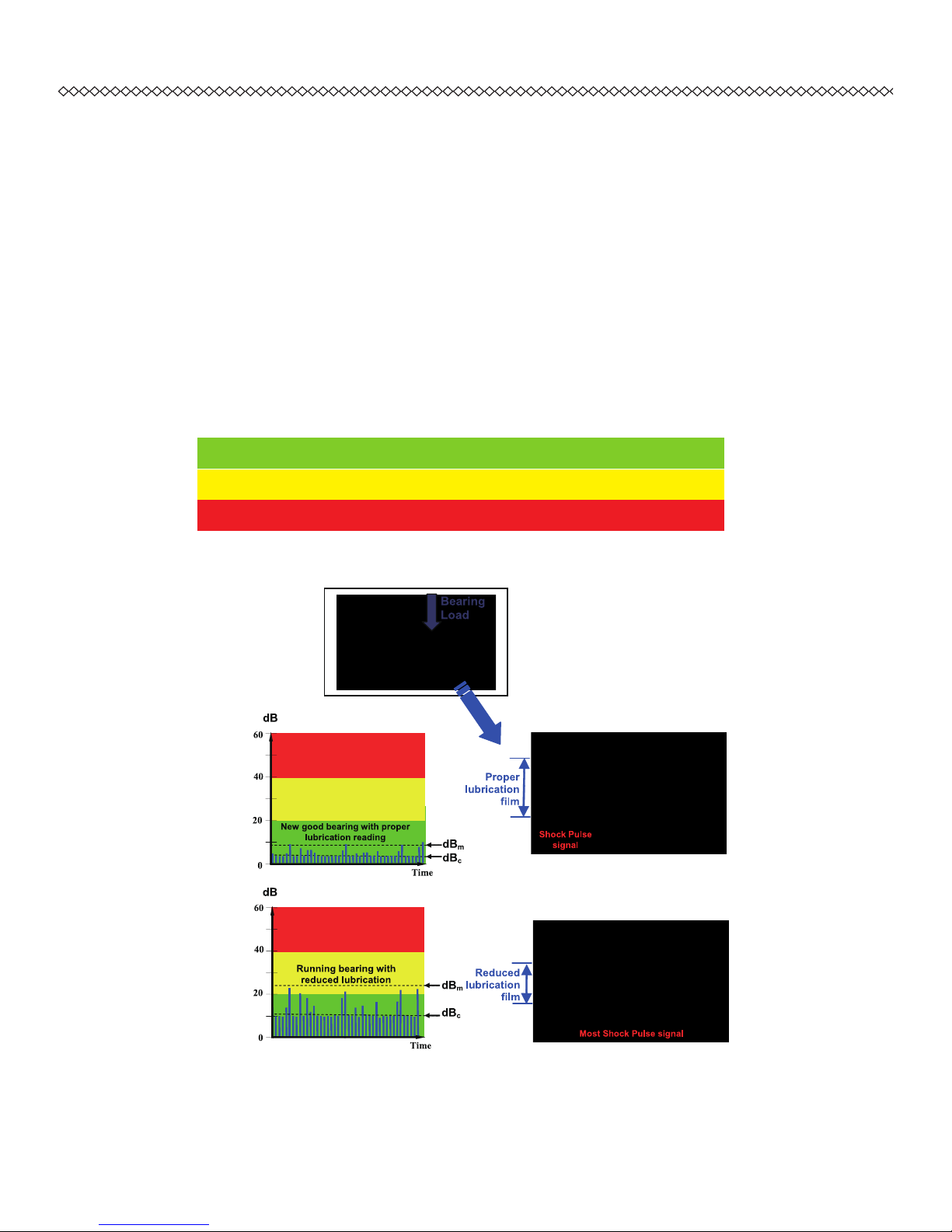
1.2 OverviewonRollingBearingConditionMonitoring
Ideally,rollingbearingelementsareseparatedbyaprotectivelubricantlm,which
impedes their collision. However, manufacturing defects, damages, which appear
duringoperation,dirtinthebearing,insufficientorincorrectlubrication–allthese
factorscausethecollisionofthebearingelementsand,asaresult,acoustic
oscillationsofawidespectrumaregeneratedinthebearingbody.
Aspeciallydesignedtransducer(patent№18652)isusedtolteroutthepartofthis
spectrumthatcarriesinformationonthebearingfaultsdetection.Thetransducerlters
thoseacousticoscillationswhicharegeneratedbythebearingdefects,andconverts
themintoelectronicsignalproportionaltothemagnitudeofshockpulsesignal,thatis
ampliedand measured bytheBT-77electronic unitintherelative units ofdecibels
(dB).
Arealnewbearingisjustfromthebeginningofitsuse,asourceofinducedvibration,
theamplitudeoftheshockpulseofwhichisdBi.
ThedBi,initialvaluedependsonthelargenumberoffactors;however,inpracticeitis
possibletolimitthemtodiameterD(mm)oftheneckanditsrotatingspeed�(rpm).The
•
•
•
•
•
•
•
2

KOHTECT BT-77
valueofdBifeaturestheconditionofanewcorrectlyinstalledandlubricatedbearing.
The shock pulse amplitude increases as a result of wear and improper use. Shock
accelerationamplitudeoverrunningthevalueofdBi -dBsvfeaturesadamage,andis
usedfortheevaluationofbearingcondition.
ThisenableBT-77totellthedifferenceofshockpulsevaluesinduceislowshockand
highshock,anormalizedmeasurementscalecalldBnisuses,seebeneathTable-1.0.
dBn = 0-25 Goodcondition
dBn = 25-40 Satisfactorycondition
dBn > 40 Poorcondition,breakdownrisk
Table-1.0
Fig-1.0
3

KOHTECT BT-77
50 -
-dBa-absolutevalueatmeasuringpoint
40 -
-dBsv -valuefeaturesbearingfailure(dBa-dBi)
30 -
20 -
-dBi-originalvalueoftheshockaccelerationamplitude
10 -
-
0 - responsethresholdofthebearingchecker
-5 -
-10 -
Figure-1.1-Anexampleofthesevaluesratio.
Patternoftheinducedoscillations,whichareregisteredbyBT-77,changesaccording
tothebearingfaults.
1.3 UnderstandingShockInduced“Carpetvalue”and“Maximumvalue”
Atthemeasurements,thebearingcheckerallowstolteroutandmeasuretwospecied
valuesoftheshockaccelerationamplitude:theCarpetvalue(dBc)andtheMax.value
(dBm).
ThedBcbackgroundvalue(theCarpet value) refers to the frequent collisions of the
bearingsurfaceroughness,dBcitgivesimportantinformationregardtothelubrication
ofthebearings,howwellthebearinghavebeenmountedandthewayinwhichthey
arebeenloaded,andisindicatedbythecontinuouslightofLED.ThedBmMaxalue
referstotheseparateshocks,characterizingthefaultslevel,andisindicatedbyseparate
LEDashes.
4

KOHTECT BT-77
Forinstance,attheshockaccelerationamplitudemeasuringofawelllubricatedand
correctly installed bearing, the dBm is only slightly higher than dBc. But when one
measures shock acceleration amplitude of a bearing having faults, these faults are
detectedbydBmmaximumvalues,atthat,thebackgrounddBcvaluedependsonthe
lubrication condition, and can grow increase substantially when there is insufcient
lubricationfollowedbyfrequentmetal-to-metalcontacts.
IncreaseofdBcbackgroundvaluemaybecausedbyotherreasonsaswell,e.g.atthe
drivecouplingmisalignment.Itiseasytodistinguishbetweenthesecases–withthe
couplingmisalignmenttherewillbethesamepictureforthebearingsonthebothsides
ofthecoupling.
Resultsoftheshockaccelerationamplitudemeasurementfordrivesbearingscanbe
inuencedby shocks produced duringthe running in ofa gear mesh, whichcan be
transferredontothebearings.However,mostlythegearteethhumissolowthatdoes
notimpedethemeasurement.
Withtheshocks,originatedbythegearwheelsdefects,thedBmMaxalueincreases
sharplyforthetwobearingssimultaneously(onbothsidesofgear).
The greatest effect from the technical state monitoring of bearings is reached when
measuringresultsarebeingputongraphagainstthetimefactor.Atthis,aforecastof
thetechnicalstatebecomespossible.Exampleofthemeasurementsresultsprocessing
isgiveninTable-1.0.
1.4 Tachometer
TheTI-7tachometeroperationisbasedonthemeasurementoffrequencyofinfrared
rayreturnfromthereectivetape(oranothermarker)xedontheturningshaft.Awhite
markerpenisprovidesinthepackagesothatusercanmarktherotortogetgood
5

KOHTECT BT-77
contrastwhentakingRPMmeasurement.
ThemeasuredRPMreadingcanalsobesavedwithinthedevicewithlenameendby
“tac”extension.
1.5 DesignofBT77
Constructively BT-77 Bearing Tester is designed in a light and strong alloy casing
protectedbysiliconsleevewiththerechargeableinternalbatterypowersupply,socket
forthemeasuringprobeandUSBportfortachometersensorsorleuploadtoPCfor
datamanagement.ThecontrolsandconnectorslocationisshownontheFig.1.2a&
Fig.1.2b.
Fig.1.2a Fig-1.2bTopviewofBT-77
1.BT-77device
2.Bearingshockpulsemeasuringprobe
3.Tachometersensorandmagneticstand
4.Socketformeasuringprobe
5.USBportforTachometersensor/PCcom
6.SocketforACcharger
7.Softmembranepushpadforoperation
8.Back-litemonochromeLCDdisplay
456
6
12
8
3

KOHTECT BT-77
1.5.1OperationKeys
TurnO� Entersetupmenu
OK/Start Return/backtoearlierstep
Adjustuporincrease Adjustdownordecrease/OFF(pressandhold)
2.0 TAKING MEAUSREMENT WITH THE INSTRUEMNT
Beforeusingtheinstrument,itisagoodpracticestocheckpropermechanicalfunctioning
ofthecontrols,connectorsandpowerstatewhenswitchon.
Note the device automatically switches off after 150 seconds when no further
operation.
2.1 InstrumentDisplayandMeasuringModes
Toswitch“O�”theBT-77bearingtester,press .Thedeviceperformselftest
asshowninFig-2.1andautomaticallyenterthefirstdefaultoperationmode-USB
interface,Fig-2.2.
ToconnectdevicetoPCforreportprintandview,makesuredeviceissetinUSB
interfacemode and press to ready for interface.Connect the USB cable
betweendeviceandPCviatheUSBport.
To go to other mode, press either or to scroll through the four operating
modeoption.
Fig-2.1Fig-2.2
Bearing Tester
KoHTECT BT-77
(c)070108 v3.01c
No. 1234455
www.kohtect.com
USB interface
*
3 . 0 2 v
25mar 07 14:30:50
7

KOHTECT BT-77
2.1.1Settingthesystemrealtimeanddate
Atanyoperationmodedisplay,press toenterdate/timemenufollowby
toseesetitems.
Press and tosettheminutesandfollow toconrmcorrectinput
setting.Thescreenproceedsandshowsubsequencesettingforhours,day,date,
monthandyeartobesetinsameway.
Whenalldateandtimesettingsarecorrectlyinput,press twicetoreturn
operationmodedisplaytobeginnewtask.
2.2 TakingBearingDiagnosisMeasurements
2.2.1Selectionandsettingupthemeasuringpoints
Whileselectingthemeasuringpoints,takeintoaccountthefollowingandseeFig3-3:
Metalcolumnbetweentheprobetipandbearingmustbe,ifpossible,straight
(don’ttakereadingsfromthecapthatcoversthebearinghousing).
Itiscriticalthatthemeasuringpointtobeselectedascloseaspossibleto
thebearing.
Whilemonitoringthebearing,usethesamemeasuringpoint.
Settingupmeasuringpoint:
Measuringpointsshouldbefreeofpaintanddirt;
Mountthe stationaryextenders(pins orbolts6-8 mm)ofdesired lengthor
provideholes for measuring probeaccess in the bearing housingslocated
behindthemachineprotectivegearsorcaps.
ATTENTION! Keep the probe location and the force the same during the measuring
cycle!
The BT-77 Tester automatically switches off after 150 seconds when no further
operation.
•
•
•
P
P
P
P
P
8

KOHTECT BT-77
2.2.2Setupinitialparameter&takebearingmeasurements
Press toturnonBT-77,press keytoswitchdisplaytobearingdiagnosis
measurementmodeshowsinFig-2.3.
Press tobeginnewmeasurementshowninFig-2.4andpress again
tostarttakingreading.
Fig-2.3Fig-2.4
Ifparametersonscreenare�OTcorrectsetandneedtobechange,press
twicetodisplaychangeofdBisetting(see note below for dBisetting).
IfdBiisunknown,press againtochangeD(diameterofshaftorbearingI/Ddia)
byusing or keytosetandpress toconrmtheDinputvalueand
gotonextsettingparameters.
ScreenwilldisplayRPM(shaftrotatingspeed)setting,sameusing or
keytosetandpress toconrm.
Thedisplaynowshows“Single”“Average”or“Contin”,setting.Tochangethe
calculationmethodbyusing or keytoset.
�owpress twicetoviewthenewlycalculateddBivaluewithchangedinput
parameters.
Ifallparameterhavesetcorrectly,press toreturnreadyformeasurement
screen,Fig-2.4.
Tobeginnewmeasurement,press tostarttakingreading.Waitformeasured
todisplaywithevaluationasshowninFig-2.5b
Note: dBican be input manually or calculate by device after input of the bearing inner
Bearings 77D11
*
2 . 7 7 v
25mar 07 17:30:59
================
D = 2 5 N = 3 0 0 0
dbi=30 Average
•
•
•
•
•
•
•
•
•
9

KOHTECT BT-77
diameter or shaft diameter “D” and RPM, “N” speed for the machine.
ATTENTION!
Measurement calculation method:
single reading with dBitaken into account. Result – normalized value of
dBm, dBcfor condition evaluation based on the technology developed
by the Central Research & Design Institute of Navy.
continuous reading with dBitaken into account. Result updates every
seconds. Press “STOP” button to end the procedure.
five readings are taken with dBitaken into account; the result is their
arithmetic mean value.
2.2.3Takingbearingdiagnosismeasurementandsave
After identied the measuring point on machine, place the probe rmly against the
machineatthedesiredmeasurementlocationandreadytotakereading.
Press andwaituntilbearingreadingisdisplayed.Whiletakingthereading,
displayshow“busy…”message,Fig.2.5a,andthemeasuringcycleis
approximately30-40secondif“Average”methodisselected.
Oncemeasurementnish,thedisplayshowsFig-5b,themeasuringresults:the
Maxvalue,Carpetvalue(dBmanddBc)andconditionofthebearingevaluated
ondBnchartasnalresult.
Fig-2.5aFig-2.5b
Tosavethereading,Press follow OKkeytoentermaindirectory.
Press again to make new directory, save, read or delete folder or press
Single-
Cont.-
Average-
•
•
dBm=
2 9
S a t i s f .
dBc=
1 8
================
D = 2 5 N = 3 0 0 0
dbi=30 Average
Max. value
Bearing evaluation
Carpet value
Input info
B u s y . .
•
•
10

KOHTECT BT-77
or toselectdesireddirectory(directorylineareshowswith)series of
numeric without “xxx.b77”or “xxx.tac” extension)tobesaved,seeFig-2.6in
section2.2.4savemeasuredfile.
Press toconrmdatasaved.
2.2.4Fileformatandopenmeasuredle
For BT-77, any measured reading on display reading is saved within the device in
standardformatwithselfdevicegenerateddirectoryorlenamesintermofdateand
time(“0325”mean25Marchand“165301”mean16hrs,53mins,01sec)followby
“b77”extensionformatfordatale,seeFig-2.6.
Fig-2.6
Toopendataleforreview,press or togotomydocumentsscreen
andpress toseeleanddirectoryasFig-2.6.
Press or tomovecursortodatale(withb77extension)andpress
toopenforview.
2.3 EvaluationoftheMeasuringResults
BearingconditionisdenedbytheshockaccelerationmagnitudedBn.
0...25dBn -goodcondition,optimaloperatingconditions;
25...40dBn -satisfactorycondition,themeasurementsaretakeninshort
timeintervaltoevaluatethetypeofcoming;
>40dBn -poorcondition,visiblefailuresappear,operatingconditionsbe
cameworse,accidentmayhappen.
/0324_170405
. .
0325_165211
0325_165301.b77
16b
Data saved
Main directory name
Back to earlier directory
Sub-dir name
Data file name saved
File size
•
•
•
11

KOHTECT BT-77
The measuring results are recorded into the report. While continuously monitoring the
equipmentcondition,itisrecommendedtousetherecordsasgraphicaldatarepresentation
toshowclearlythetendencyofconditionchangeatthemeasuringpoints.
Table-2
DiagramsintheTable-2showasfollows:
Bearing№1isingoodtechnicalcondition
Afterthemeasurementdated15.02.90thelubricationwasreplacedinthebearing
№2,presentlythisbearingisingoodconditionandneedsclosemonitoring(more
frequentmeasurements).
Bearing№3isingoodtechnicalcondition.
Conditionofbearing№4isgettingworse,afterthemeasurementdated15.03.90
thelubrication was replaced, no positive resultswere shown, it is advisable to
replace the bearing to avoid any serious faults (bending of the shaft, impeller
break-away,etc.).
2.4 MeasuringRPMbytheTachometer
2.4.1SetupinstrumentandmeasuringRPM
Applyreectingtapeormarkontheshaftwhichrotationfrequencyshouldbemeasured.
Themarkshouldbecontrastagainsttheshaftmaterial(alightmark-onthedark
Pump inventory numbe1121r
Bearing № 1 Bearing № 2 Bearing № 3 Bearing № 4
Date 10 30 50 10 30 50 10 30 50 10 30 50
18.01.90
31.02.90
15.02.90
22.02.90
01.03.90
15.03.90
22.03.90
28.03.90
1.
2.
3.
4.
12

KOHTECT BT-77
background,adarkmark–onalightbackground).
Reectivemarkingshouldnotlessthan20mmlengthonshaftfortachosensortotake
speedreading.
Placethetachometersothatyoufollowtherecommendationsonpositioningawayfrom
themeasuredobject.Selectthelocationofthetachometerthatwillprovidethereliable
andstableresponsefromthemark.Itisrecommendedtoplacethetachometeratthe
angledifferentfrom90degreesand10-20cmawaytothemarksurface–thiswill
decreasefaultresponsefromthesurfaceoftheshaftsurface.Useretro-reecting
tapeasamark.(Itispossibletousethecorrectionuid“Stroke”toapplythemark).
2.4.2MeasuringRPMbytheTachometer
Press toturn on BT-77,press key toswitchdisplay toTachometer
measurementmodeshowsinFig-2.7a.
Fig-2.7aFig-2.7b
Press twotimestostartrpmmeasurement.
Press torecordmachinerotatingspeedanddisplayRPMreading,Fig-2.7b.
When finish measuring, press save result or press to return to
programmodeoptionwhenRPMnoted.
•
Tachometer
*
2 . 7 7 v
24mar 07 17:30:47
T a c h o E P C = 1
RPM
3004.81
•
•
•
13

KOHTECT BT-77
3.0 ROLLER BEARING CONDITION MONITORING BY THE SHOCK PULSE
METHOD (MEAUREMENT METHOD)
3.1 WhatisShockPulseMethod(SPM)anditbasis
DesignationoftheShockPulseMethod(SPM)isasignalprocessingtechniqueused
tomeasure rolling bearing condition and the quality of their lubrication in the motor,
pumps,separators,turbocompressorsfordieselboost,etc.Usingtheinstrumentsto
measureshockpulses, one can determine the air or gas leaks vialoosenessinthe
high-pressurevesselsorpipes.TheresearchworkconductedatCentralResearch&
Design Institute of �avy allowed expanding the performance capabilities of the
instruments.Shockpulsecheckershavesettobeusedfortheevaluationofcondition
ofhigh-pressurefuelpumps,dieselinjectors,valvesofpistoncompressors.
The Shock Pulse Method (SPM) was developed by a Swedish instrument company
andbasedonmonitoringandanalyzingofhighfrequencycompression(shock)waves
causedbymechanicalimpact.Accelerationofmaterialparticlesgeneratespressureor
shockwavethatpropagatesasultra-sonicfrequencybandthroughtheobject.Inthe
initialphaseofimpact,theaccelerationofmaterialparticlesdependsonimpactvelocity
andisindependentofthemassofcollidingobjects.Withinshortperiodandthereisno
evidentdeformation.Thevaluewaveshockistheimpactvelocityofcollidingobjects.
In the second phase of the collision, the surfaces of two objects are deformed; the
energymovementdeclinestheobjectandgeneratesvibrationsthatarediagnosedby
thevibrationanalysis.
Piezoelectrictransducerisusedtomeasureshockpulse;vibrationandnoisebackground
donoteffectonit.Thetransducerselectricallyandmechanicallytuneto28…32kHz.
Shockwavecausedbythemechanicalimpactgeneratesthedecayingshockvibrations
intransducer.Themaximummagnitudeofthisdecayingvibrationisrelativetothevelocityof
theimpact(v).Sincethedecayingtransientiswelldenedandhasconstantdecayvalue,it
14

KOHTECT BT-77
canbeeasilylteredoutallothervibrations,i.e.vibrationfrequencies.Theshockpulse
methodinvolvesmonitoringandanalyzingthedecayingtransientprocess.
3.2 HowShockPulseMeasuredandEvaluatedforRollingBearing
Theouterracewaysofthebearingalwaysfeatureroughness.Thereforeabearingunder
normaloperatingundergoesthemechanicalimpactsandcreatesshockpulses.Shock
pulsevalueisdependentonthebearingsurfaceconditionandtheperipheralcondition
ofthebearing.Shockpulsevalueoftheregularbearingfeatures1000timesincrease
sincethetimeabearingisnewuptothemomentwhenabearingneedsreplacement.
Because of the very large dynamic range shock pulses are measured on a decibel
scale.
Empirical tests showed that even the new and lubricated bearing generates shock
pulses.ThevalueofthisinitialimpactissetasdBi(dB,initialvalue).Asthebearing
wears,thevaluedBa(averageshockpulsevalue)increases.�ormalizedvaluedBnfor
thebearingcanbeshownasfollowsdBn=dBa-dBi
(BearingLife)
Fig-3.1.depictsdBnandbearingliferatio.
Inorderfortheshockpulsesreadingtobequicklyandeasytoevalutatedonthebearing
condition,insimpleunderstandingscaledBnhasbeenderived.Itcategoriesthebearing
condition into three different zones by indicating the extent of bearing damage from
goodtopoorcondition,Fig-3.1:
100%
0
50
20
40
60
dB
n
100%
0
50
20
40
60
dB
n
15

KOHTECT BT-77
dBn < 20 Goodcondition
dBn = 20-40 Satisfactorycondition
dBn > 40 Poorcondition(i.e.bearingneedreplacement)
Table-3
3.3 EvaluationofBearingConditionwithBT-77
Technicalconditionofthebearingismainlydeterminedbythelevelandrelationoftwo
measuringvaluesdBmanddBc.
dBm-maximumvalueofnormalizedsignalindecibel.
dBc-carpetvalueofnormalizedsignalindecibel(backgroundofthebearing).
However, under the work of the bearing the peak strikes have not only varying
magnitudes, but frequencies as well. Fig-3.2 shows the typical examples of the
evaluationofbearingconditionandoperatingconditions(installation,rollerbearing
fit,alignment,lubrication)basedontherelationofshockmagnitudevalue(reading
ofscaledBc)andfrequencyvalue(numberofshocksperminute):
Fig-3.2
dB
m
60
40
20
0
Time
dB
c
dB
n
dB
n
60
40
20
0
Time
dB
m
dB
c
dBn
60
40
20
0
Time
dBm
dBc
dBm
dBc
60
40
20
0
Time
dBn
dB
c
60
40
20
0
Time
dB
m
dB
dB
n
dB
m
dB
c
60
40
20
0
Time
dB
dB
n
16
Table of contents