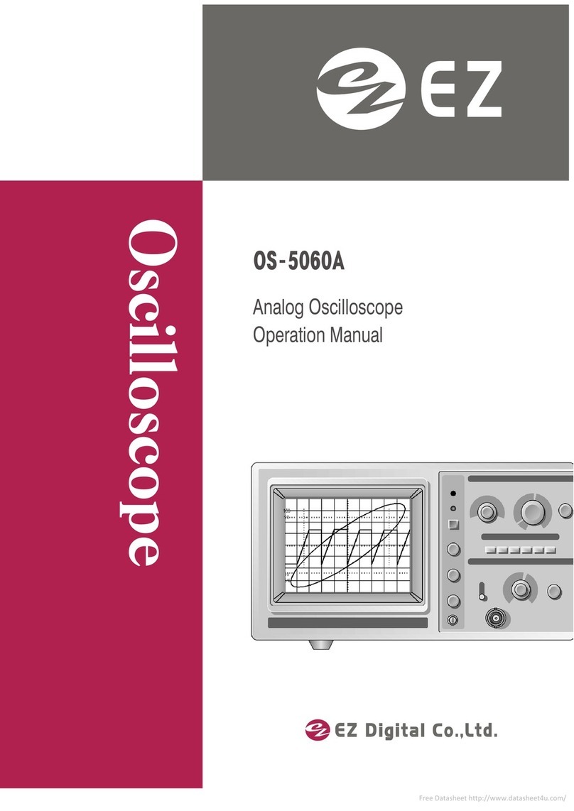
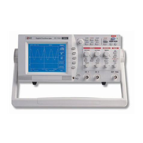
EZ Digital OS-3060D User manual

Oscilloscope
Digital Storage Oscilloscope
Operation Manual

@
ez
Digital Co.,Ltd.
05-
30200/400/600
•
----
fi\
;::..
:;::::.~
=.J
V
:;:;;;.
......
:;:;:.
......
~
()
!Q)l
0· , · ' • . • ' " , . . , ' • •" . ,
11" ' . ., . ' • • • • ", . ' . ' • • ,
.'
•••• , . , .
'.
"
Digital
Storage
Oscilloscope
Operation
Manual

DE
CLARATIO
N OF CONFORMITY
ac
cording
to ISO
/lE
e
Guid
e22
and
EN
45014
Manufacturer's
Name:
Manufacturer's Addres
s:
Declares thatthe product :
Product Name :
Model Number
s:
Date:
EZ Digital Co..
Ltd.
222-28. Nae
-dong,
Ojeong-gu.
Bu
che
on-s i, Gy
ecngg
i
-do
R.O.K, 421-160
OSC
ILLOSCO
PE
05
-302
00
,
05
-30400
,
05-306
00 ,
Aug.
18. 1995.
Conforms to the following product specifications :
Certified by
TUV
Rheinlan d
Safety:
EMC :
Supplementary Information:
EN 61010-1: 1993
(l EC 1010- 1: 1990+
A1:1
992, modified )
EN 50081-1: 1992
EN 50082- 1: 1992
The
produ
ct
herewith
complies with the requ
ireme
nts of the Low Voltage
Directive 73
/23
/EEC
and
the
EMC Direct ive 89
/336/EEC
.
Bucheon, Gyeonggi
Location
.
C.
)'
.
/LU'J?
Cheal Young Kim
Quality As
suran
ce
Manager

Safety Summary
Safety Precautions
Please take amoment to review these safety precautions. They are
provided for your protection and to prevent damage to the osc
illoscope
.
This safety information applies to all operator and service personnel.
Caution and warning statements.
CAUTION Is used to indicate correct operating or maintenance
procedures in order to prevent damage to or destruction
of the equi
pme
nt or other prop
ert
y.
WA
RNING
Ca
lls
attention to a potential danger that reqwres correct
procedures or practices in order to prevent personal injury.
Symbols
Cautionj refer to accompanying documents) and Warning,
Protective ground(earth) symbol.

Introduction
Thank you for
pur
chasing a EZ product. Ele
ctr
onic measuring instrume
nts
produ ced
by EZ Digital
ar
e high technology products
mad
e under
st
rict qu
alit
y control.
We guarantee their exceptional precision and
utmo
st reliability. For proper use of
the product please read this user
manual
carefully.
~
EZ
Digital
CO.
.Lt
d,
Note
I. To fully maintain the precision and reliability of the product use it within the range
of
sta
nda rd
set
ting
(tempe
rat
ure W'C - 35·C. hu
midit
y45%
-8
5%) .
2. After turning on-power. please allow a pre-heating period of as long as some 15 minutes
before use.
:J
.
Thi
s equip
ment
should be used with a triple line power cord for safety.
4. For quality improvement the exterior design and specifications of the product can be
changed without prior notice.
5.
If
you have further questions concerning usc. please co
nta
ct the EZ Digital service
center or sales outlet.

Warranty
Warranty service covers a period of one year from the
dat
e of original
purchase.
In case of technical failu re within a year, r
epair
service will be
provided by our service center or sales outlet free
of
charge.
We charge customers for repairs after the one-year warranty period has
been expired. Provided that against any failure resulted from the user's
negligence, na tural disaster or accident, we charge you for repairs
regardless of the w
arr
anty period.
For more professional repair service, be sure to contact our service
center or sales outlet.

- CO
NTE
N
TS
-
l.
Des
cr
iptions
of
the
prod
uct
\-1. Introduction
1-2. Specifications
1-3. P
oint
s to bc checked prior to usc
1-4. Accessories
2.
Op
eratin
g in
stru
cti
on
s
2-1.
Fun
ction of each block
2-1-1. Display and power blocks
2-1-2. Vertical amplifier block
2-1-3. Sweep and trigger blocks
2-1-4. R
ead
out
2-1-5. Storage block
2-1-6. Miscellaneous featu re
2-2. Basic func tions and measurement
2-2-1.
Con
nection
of
measuring signals
2-2-2. Adjustment during initial operation
2-2-3. Data display
( I) Real time m
ode
display
(2)
Storage mode display
2-2-4. Real time mode measurement
(()
Single-trace measurement
(2)
Dua
l-trace measurement
(3)
Trigger selection
II
I I
13
17
18
14
21
21
·····
21
23
·
·····
26
27
28
29
24
30
33
33
35
38
38
.
~
<)
-I
I

(4) Addition
and
difference measurement
(5) X-Y measurement ··
(6) Delayed-time axis operation
2-2-5. Digital storage mode function
(
I)
Normal
storage mode (MO
DE)
·
(2) Equivalent sampling mode
(3) Roll
mod
e
(4) Single mode
(5)
Hold mode
(6) Save mode
(7) Save memory display (RECALL)
(8)
X-Y plot output
(9) Hori
zont
al magnification display
( 10) Interpolation
( I I ) ALT
MA
G .
( 12) GO
-NOGO
·
(13) Menu mode
(14) X - Y measurement
2-3. Measurement applications .
2-3-1. Ampl itude mea
sur
ements
2-3-2. Time interval mea
sur
emen
ts
2-3-3. Frequency meas urements .
2-3-4. Phase difference mea
sur
ements
2-3-5. Rise time measurement
44
45
46
49
49
49
51
52
53
53
53
54
54
57
58
59
59
65
66
66
70
72
73
77

3.
X-Y
digital
output
3-1. Application X-Y plott
er
3-2. Plotter specification
3·3. Connection
3-4. Setting
3-5.
Operation
3-6. RS-232C interface
3-7. Major trouble,
4.
Serial
commu
nication
using RS-232C
4-1. Introduction
4-2. Specification
4-3.
Connector
pin
arrangement
and
signal descripti
on
4-4. C
onne
ction
4-5.
Operation
and
c
ommand
4-6.
Transmission
/reception
dat
aformat
4-7. Separating
chara
cter
4-8.
Abn
ormal operation
handling
RO
80
80
R5
85
.···· 90
90
90
91
..···· 9 \
91
.......
. 91
93
94
96
102
102
4-9. RS-232C interface cable connection
and
instrument operation .... 102
4-10.
Generation
of d
ata
tran
smissi
on
/reception program
4-11. Key cause
of
abn
ormal
data tr
ansmi
s
sion
/reception
4-12.
Program
examples
\0 2
....
···1
0:1
\0:1

5.
Use
r maintenance
guide
J J I
5-1. Cle
anin
gJ
II
5-2.
Calibr
ati
on
JI I
6. OS-
3IXX)
DSRS diugrum
-,
J12
6-1. External views J12
6-2. Block diagram
II
.'

1.
Description
of
produc
t
1-J. Introduction
This
product OS-3000DSRS is the 2 c
han
nel digital storage oscilloscope
which is equipped with
ND
converter.
It
combines
the benefits
of
digital scope to measure, store, interpret and
commu
nicate the rapid trace, with the benefits of analog scope to measure
the wide
band
width, 2 time axis generator, delay sweep and separated TV
trigger signal.
It
reduces the mea
sur
ement error,
and'
uses 6% squared type CRT with
inte
rna
l fl
our
esc
ent
scale which enables to take the
phot
ograph of
observed waveform.
(l)
High speed optical frequency band width
ND
converter installed on each c
hannel
samples the
input
signal at
the max. rate of 20MHz samples/sec. Any signal with perfect
rcpcat
edn
ess can be stored. (Max. 20-60 M
Hz
)
Thi
sproduct can be used as
an
ordinary real time oscilloscope with
frequency rangebetween 20
and
60MHz.
(2) Large storage capacity
Each
channel
has 2kW memory. Since
it
can
indicate the waveform
composed of
IkW
data
, it measures any rapidly
cha
nging transition
trace with high accuracy.
(3)
Wav
eform save
It
has 1kW memory to save two waveforms stored in each channel.
(4) Multi-Function
It
has a variety
of
following functions to interpret a wide range
of
signals :
- Roll
mode
function to mea
sur
e low signal.
-Average function to elimina te noise from the signal and to mea
sur
e
the pure signal.
II

(5)
Output
It
uses bot h RS-232C interface function to input/
output
the digital
data
to the personal com puter,
and
RS-232C to
cond
uct screen h
ard
copy
thro ugh digital plotter. It also interprets and records the stored
data
.
(6)
CRT
and cursor readout
It can pro mptly perform the
operation
and
meas
ure
ment
using
bot
h the
CRT r
ead
out function to display the set information of
pan
el a
nd
the
cur
sor
r
ead
out f
unction
to display the voltage difference (8 V). time
difference (8 T) and frequency difference
(l
/8
T)
between two
cursors.
12

1-2.
Spec
ificatio
ns
Spec. Model OS-J0
201l
OS-J04
00
OS-
JOWO
-CRT
1. Con
figu
ra
tion and 6-inch
rec
tangular
screen
with internal graticulc ; Sx 10 DiV
useful
screen
(1div= [
em
), marking for mea
surem
ent of
ri
se time.
2mmsubdivisions along the cent
ral
axis.
2. Accel
eratin
g+1.9kV approx. +11.5kV
approx
.
potential
(ref. cathode) (ref. cathode)
J. Phosphor PJI (standard)
4. Focussing po
ssible
twith
autofocus
correc
tion
circuit)
5.
Tra
ce
rotati
on
provided
6.
Scal
e
illumin
ation
variabl
e
7. Intensity
control
provided
-
Z-Axis
input
(Intensity Modulation)
I. Input signal
Positive
going
signal
decreases
inte
nsity.(+
5Vp-p
or m
ore
signal
cases
no
ticea
ble modulation at
normal
intensity
senings.)
2. Band
-wi
dth DC-2MHz(-3dB)
DC-3
.5MHz (-3dB)
3. Coupling DC
4. Input
impedance
2a-3Ok-o
hms
5. M
aximum
i
nput
voltage
30Y
(DC+
peak
AC)
*
Vertical
Deflection
I.
Band-width
(-3dB) DCto20MHz
normal
DCto
40MH
zno
rmal
DCto60MHz
normal
DC
coupled
DCto 7MHz
magnified
DCto 7MHz magn
ifi
ed DCto
IO
MHz
magnifie
d
AC coupled
10H
zto
20MHz
normal
10Hz
to
40
MHz
no
rmal
10Hz
1060MHz
normal
10Hz
10
7MHz
magnified
10Hz
to
7MHz
magnified
10Hz
10
IO
MHz
magnified
2. Modes CHI. CH2.ADD. DUAL CHI.C
H2,ADD.DUAL
(CHOP;TIm
eJ
div switch -0.25to 5m
<,
(CHOP :
Tune/div
switch
ALT
;Tim
cJdi
vswitch 2ms10 O.211s 0.25to5ms
ALT:Tim
cJdiv
switch
2m
st
o
O.
I
I'S
3. Deflection Factor SmY/div to SV/div in 10
calibrated
steps of a
1-2-5
sequence.
Continuously
variabl
e
between
steps at least I : 2.5
xS MAG;
ImVldiv
to
IVidiv
in
IO
ca
librated
steps.
4. A
ccura
cy
normal
;+3%. magnified; +5%
5. Input i
mpe
dance approx.
IM-<>hm
in
parallel
with
2SpF+3pF
6.
Maximum
input
voltage
Direct
;
3OOV
(DC+peak AC), (with probe;
refe
r to
probe
s
peci
fication)
7.
Input
couplin
gAC
-DC.GND
8. Rise time 17.5n
sorle
ss 8.8nsor less 5.8ns or less
(s
On
sorless;x5) (s
On
sor less;,5 ) (35ns orless;x5)
9. CHI out
approx.
20mY
/div
into
50 ohms ; DC to
IOM
Hz (-3dB)
10.
Polarity
inversion CH2
only
11.
Signal
delay
none delay cable supplied
13

.- OS-.'020D OS -
.'060D
Spec.
--------
______
Model OS-.'O·jOD
*Horizontal Deflection
I. Display modes A, A int, B. B TRIGD. X-V
2.
Time
base
A
O.2i
'sh
Jiv
10
O.2sid
iv in 19 calib
ra
ted steps, 1
-2-5
sc- 0.1
P~/
di
v10
O.2s-'
uiv in 20
qucncc. uncalibrutcd continuous control
bcrwcc
ncal
ibra
ted
steps
1-2-5
sc-
s
teps
at least 1 : 2.5 quence uncalibrated con-
tinuous con
tro
l
between
s
te
ps at least 1:
2.5
Hold-off time va
ria
ble
with
the
holdolT
control
3. Time base B
Ool/
Js/
div toO.2/ls.div in 7 ca
librated
s
te
ps.
1-
2-5 se- 0
.1
}Js.'di
v to
IO
IJs
h.l
iv in 7
qucnec. calib
rated
s
tcps
t-z
-S
sc-
quence
Delayed s
wee
pI div or less to 10 div or more
Delay
tim
e ji
tte
rbe
tte
r than I : 2
(xx}()
4. Sweep magnif
ication
IOtimes (maximum sweep
r..Ll
c;20n\-idiv) l
Otirnc
s
tr
nacimurn sweepI
NOle;50ns/div, lOns/div of A
TI~
lE
BASE
are uncalibrutcd. rate; I
On
s/div
5. Accuracy + 3%. (ot 10 50t ).
additi
onal e
rro
r for
magn
ifier
+ 2%
*
Trigge
r System
I. Modes AlITO. NORM. lV-V.
lV
-H
2. So
urce
CHI, CHl,
LINE.
EXT
3. Coupling AC
4. Slope +or
5.
Sens
it
ivity
and
2O
Hz
·1
M
Hz
lM
Hz
·1O
MHz
2O
Hz
·1
M
Hz
2M
Hz-40
MH
z
2O
Hz·1
M
Hz
lMll
z.ffi
Mliz
F
requ
ency !NT
U.S
div l.Sdiv INT O.5div 1.5div INT
Il.Sd
iv l.Sdiv
AlITO. NORM
EXT
O.2Vo-o
O.8Vo-o
EXT
O.2
Vo-o O.8Vo-o
EXT
O.2Vo-o
O.8
Vo-o
lV
-V. lV-H at least I div or
l.O
Vp-p
Composite Sync.
6. External triag" fMo hm in pararall with approx. 30pF
Input Impe ance
Max. input voltage 250V(LlC+p
cak
AC)
*X
·y
Operation (same as CHI except for the following)
l.
X·'
3Xi
sDefl
ecti
on factor: same as that of CHI
Accuracy; ±5%
Freq
uency response ; DC to 500k
ll
Z(-3dlll
~
.
Y axis same as CH2
.
~
.
X·Y phu-,e
dittcrcu
c
...
·3" or less (at DC to 50kHz)
*Readout Function
I. Cursor r
eadou
tVoltage
re
f
ere
nce ~V;
~-REF
f
unc
t
ion
Time
re
fere
nce
~
T
;
~
·
R
E F
Freque
ncy
refe
ren
ce II
~V;
~
-REF
2.
Panel
sett
ing Vertical axis (CHI. CH2)VfDlV. UNCAL. MAG (convened value)
di
splay
sHorizontal axis : SfDlV. UNCAL. MAG (convened value)
3.
Effec
tiv
e
cursor
V
ert
ical : withinf 3div
range
from
c
enter
Ho
ri
zontal
:
with
inf4div
graticule
4. Resolution 1(25 div
1
-1

Spec.
Model
()
S
-
Jll~O()
OS ·.'O·I
O»
(lS
-'ON))
• Digital storage function 1()l)l
)W
tlnh
/C
H
I. Display memory I00:IWortJ
...
elf
»:
2
2. Sav'c memory
3. Acquisition memory Sus/div - 2
0sl
div : 2000word,
IC
Ii ! Susl div
-20
sldiv :
2000
w
ord
siCH
0.2u
sld
iv - 2sl div :
IOOOw
ords/
CIi
o
.lu
,ldiv
-2
usl div :
IOOOw
ord
siC
H
-
4. Vertical resolut ion
2
~ p
o
i
nL
t1
i\
5. Horizontal resolution lOOPoint
/div
6. Maximum sapmling rate 20 Msl s
7. Digital Band Width SM
lIl
(4 samplesl Cycle)
single shot event 20MII, 4OMI17 6OM
II,
.
"':
I'll..'II\ v
\,.'\
cru 7MHz at Y axis xS 7MJlz 31 Y ax is x5 7MHz at Y axis xS
MAG MAG MAG
8. Data acqu isition · NORM mode : storage the data each time trigger
method · AVG
mode
: averaging from 4to 256 times
· ROL L
mode
: da ta is
continuo
usly stored on the CRT
· 1I
0LD
mode
: data is held for
'h
e NORM. AVG. ROLL
· SI
NGL
E
mod
e:
waveform is held after stored
9. Display Function ·SM
OOTI
i : the storage waveform is displayed by dots or s
moo
th
·I
l'o
TE
RPO LAn ON : the sto rage wa
vef
orm is displayed by dot.
linear of sine interpolation
· ALI MAG : Simultaneo usly dis playi ng the original
wavef
orm and its
magnified waveform
·
GO
·
NOGO
: judgement and comparing of acquisition signal
10. Data save Up to IwO
sto
ra~
data can be saved.
Saved data can reca lled to tnc display wheneverreauired.
I I. Pre-trigger Variable (0.04 div step)
12. Plotter plotter output of the CRT
d~
layed
information to an IJP
·GL
plotter via the RS·232C inte ace.
1
,'\
"Il.
L1
.1
outp
ut RS·232C
14. Magnified display x \0 by Tirne/ div switch or MAG switch
15. X-Y operation Sigle trace X-Y X axis - C H 1
·X
axis - SA
Yaxis - CH 2 Y axis -
S8
Dual trace X-Y Xaxis - CH I
Yaxis - CH 2
Sensitivity X
axis
: CII I
ImV
-S
V/div ±S%
Y axis : CH 2 Im
V-
S V/div ±S%
Phase error 3" or less from DC
-SO
Kllz
16. Swee p time O.2I
Js.
'div- 20s div 0_11'-dl\
-2
0" di_
repetitive signaLO.2Ils/di",'
-2
/Js
/div repetitive signal:O.1jJs Ji \ - 2ps div,
roll mode:O.5j
'S,
,'di\"-20s.'di\ roll mooe:O.5j
'S.
'd
i\"
- 20s.'div
ALT:
O
.5
1
1~d
i
v- 20s div AI.T O.I
,><;Idiv"().5
msldiv
CIIOP:Imsldi_- 20, 'div CHOP:O.I
ms
'd
iv-2
0s!div
17. Readout function (Panel seuing disp
ld:
)
V/ div. uncal. MA .
Sidiv, uncal. MAG _
X-Y.
T
ri
~g
er
point, no. of averaging.roll mode. smoolhing.
interpola tion method.
save
mem
ory information.
trobe
seni ng
( ursor reado ut)
Voltage difference 6V : o -Ref
Time
diff
erence ,0, T : t::.-Ref
Frequency II t::.I : 6-Ref
Pretn gger 'm.G : 6
I:;

S
f'L"
.-
\l
uJd
()S
· .
l
O
~
()1>
OS
-.10.1
(1)
OS·.1( 01)1)
*
Calibrat
or
'(
probe
~
I
J
j )
approx. lU I, fn
..
"Ju
clli.) ',
05\
'
(.t]%
)' q U.IH.'\ \
;j\
I..'
Juty rall\l 50%
*Power Supply F , ,
I. Voltage range voltage range
..
'1
I()()
( 40
-I
IOV)
'AC"
2A F2A
120( IOK- I32V)/AC
220( 198 . 242V)/AC IA FIA
2.1(~207
·
250V)iAC
2. Frequency 50 I1'011,
3. Power consumption appro,. 70W. upprov. 7
11
\\ ..ppm\ . 70W.
*Physical
Characteristics
I. Weight approx. 8k
Je
approx
.8kJ;::
"Pp'O\
. Ski:
2. Dimension 320 m W) X 140 m (
10
X 430 m (LJ
*Environmental
Characteristics
I. Temperarure range + 1Ot: to +
3st:
(+
5O
'F to +9S'F)
for rated
opera
tion
2.
~
t
a:<
.
ambient
operating temperature a
t:
to +
4O
t:
(+
3tF
to + 104'F)
3. M
a:<.
storage
tcmerurure -
2O
tto + 70
t:
(-
4'F to +ISS'F)
4. Humidity mnge for
rated
operation 45" to +
85"
R11
5. Max. ambient
operating humidity
35"
to +85% RH
• Safety Er\61010-1 overvoltage CAT
IT.
degree of poilulion 2.
Approval:TOVI
, B tC lnt
erf
erdnce:EN50081-1
Susceptab,hty:EN50082-1. IEC801-2, 3. 4
cCautiono.Sourccs like small hand -held radio transceivers, fixed station radio and television
tran
smitters. vehicle radio
tran
smitters anJ cellular phones generate electromagnetic radiation
that may induce
voltages
in the leads
of
alest probe In such ca ses the accu racy
of
the
oscilloscope cannot be guaranteed due to physical reasons.
16

1-3. Points to be checked prior to use
Comply with the following procedures for safety and to prevent damage to
the product prior to operating this product.
1-3-1. Line voltage selection
Before use, check the voltage.
This instrument must be operated with the correct line voltage selector
switch setting to prevent damage in reference to table I-I.
To change the line voltage select
ion
:
1. Decide the voltage range and fuse in reference to table I-I.
2. Make sure the instrument is disc
onnect
ed from the power source.
3. Pull
out
the Line Voltage Selector switch on the rear
pan
el. Select
the arrow mark position of the switch from Table I-I. Slide the
arrow
mark
to the desired position
and
plug it in.
<Caution> : This product
has
the gro
un
d chassis (3 wire power cord is
used). Check whether any
other
equipment connecting with
this product requires the transformer bef
or
e use. If so, do
not connect the DC/AC or the hot chassis equipment if no
transformer is available.
Do not directly con nect it to the AC power
nor
to the
circuit directly
con
nected to the AC power.
Otherwise serious personal injury or
damag
e to this product
for a long time without trouble.
Table 1-1. Line voltage selection and fuse ratings
Line voltage Arrow mark position Fuse Ratings(250V)
ULl98G IECI27
90 - IIOVAC 100 2A F2A
108 - 132VAC 120
198 - 242 VAC 220 IA FIA
207 - 250 VAC 230
17

I copy
l EA
2 EA
IEA
1-3-2. Installation and handling precautions
When placing the OS-
3()()()DSR
Sin service at your workplace, observe the
following precautions for best instrument perf
orm
ance and l
on
gest
service life.
1. Avoid placing this instrument in an extremely
hot
or c
old
place.
Specifically, don't leave this instrument in a close
car
,exposed to
sunlight in midsummer, or next to a space heater.
2, Do not use this instrument immediately after
brin
ging it in from the
cold. Allow time for it to warm to room t
emp
e
ratur
e, Similarly,
don't move it from a warm place to a very cold place, as
condensation might imp
air
its operation,
3. Do not expose the instrument to wet or dusty environments.
4. Do not place liquid-filled containers
on
top
of
this instrument.
A spill could seriously damage the instrument.
5. Do not use this instrument where it is subject to severe vibration,
or strong wind.
6. Do not place heavy objects
on
the case, nor block the ventilation
holes.
7. Do not use this oscilloscope in strong magnetic fields, such as
near
motors.
8. Do not insert wires, tools, etc. through the ventilation holes.
9. Do not leave a hot soldering iron ne
ar
the instrument.
10. Do not place this oscilloscope upside dow down on the ground,
otherwise damage to the knobs may result.
11. Do not use this in
strument
upright while BNC cables are attached to
the rear-panel connectors,
This
will damage the cable.
12. Do not apply voltages in excess of the m
aximum
ratings to the input
c
onn
ectors or probes. (Refer to 1-2 specification)
13. This oscilloscope is 10 use UL listed double insulated probes only,
-4. Accessories
The below listed accessories are
con
tained in the
pac
kage
of
this
instrument.
( I) Operating m
anual
(2) AC power code
(3) Probc
(OPTION
)
(4) Fuse
18

2. O
pe
rat
ing
Instructi
on
s
(A)
FR
ONT PANEL IT
EM
S
35 20 33
WAItN'N(;
.........
"
.......
"'
-
._"'
..
"'
..-
....
C......
ToO/<
........
__
..
,-
...-s
' .... .
..........,."""
.
.
..
_
~
.....
."...
4 ''''
__
.'''
,
,. '"
7 8
(B)
REAR
PANEL
ITE
MS
Fig. 2
-1
.
05
-3020D front/rear views
19

~
r
~--
I
"'"
1'
I
.''''-
~
:,
:0:
'.-
-,
~:;
..
..
'',,);,'
,.,.?
~
c=j'1
Ii
I
'IT
r-'
"
..
ss:
~
d
f
'-
-
~
-
0'
-
---f"
-----+---
~
.
Lo
I~'
©
" ;'
,
...
a,0 0 Ll'LJ':
!..
..
,_. . . " _ ., J
T
.
~
-
..
"
Iq.
..
_- , "
~
~
"'
-
,
::
eMf!'!)'!
W5
i
C)
~
~
~
~
!
'
S>
l~~
r-C::I
. • == L:..I
L..J
L.J
~
~'-
<"
_
I0 -· -' °' = .
..
•. - _ .. .
~
."
-........c:::J
4 •
DO
~OCJCJ
J0
~
-
~
-
-~'
~
,,..',
9.
©
~:
:
O~ O
§g
o::OU
©
~
.. .
(I)
-t
:
~
~~
~
~
......
~&
I
---
--
ICH1
(rJ
0
.:::
,
,,
I,
II
"
..
..
...
,
~
....
I
'·
~
~
'
-
_ .
n.
_A'::'"A:
I
-,
..
@&,
," :,\
<6:
.0
@i
~
o
; o¥
iB ., . -
"'
J
'-._-
'...
...
....
.
..
_- -
...
-
0'
~~
~
~4:
C)
--=
·.
==
ClCJc:::l=
_ ...
"'00
D O' 0 0 0 0
--=
·.
-,1/" !!
II
,
C)
~
-
~
-
_
.
~
,..',
©
~
:'0 :' c
~
CD
.'0 .
©
~
9-
- ) I •
/,,,
...
-- .,'"
(I)
&
~
~
-c:
il:h.
~
"",,~~
,
c-- -
--
I
;~
"
.
)
CHI
:Z:
C
H
2
1!lI
S~
~
",:
,
-,
-, ,
lA
-_ i
..
'h U ' ,
/
....
,~~
~
.-._
..... _-
I
..
~
«
(j
1
Q
©
~
'
®§
~
I.
.:
,; .J : '
",
'
,'
R.,.
_.
~J
,, - - , ,
-oJ
. , ..
~
~,!IZ;.?
~,t.
.
0
--=
==
c.J
CJ
CJ
CJ
......
-.
0 = _
aoro
__
--=
·.
==
CJ
CJ CJ
ca
I,i
ll",
41
I
I
~
~
-
~
-
_.
~
~ ~
,.I
@5l
"
©
~
::0,:.©
CD
.'
() . 8
:-
9.
-''--, ' - .
...
"
/,-,..
~
......
~
~
I!
(I)
'
'''.
~
~
......
~
I-._-..-
--
I- -
~I
( Hl
l[
( Hl lt ~10:.
05-300005R5
Front Views
20
05·30200
05
·3
0400
05
·30600
This manual suits for next models
2
Table of contents
Other EZ Digital Test Equipment manuals
Popular Test Equipment manuals by other brands

Factair
Factair F6001 operating manual

Keysight Technologies
Keysight Technologies U1610/20A Service guide

Dongguan Xin Bao Instrument
Dongguan Xin Bao Instrument XB-OTS-106 Operation manual

Keysight
Keysight E7515B UXM 5G Getting started guide

MARTINDALE
MARTINDALE E-ZeTest EZ2500 instructions

IDEAL INDUSTRIES
IDEAL INDUSTRIES TRACETone 62-140 operating instructions