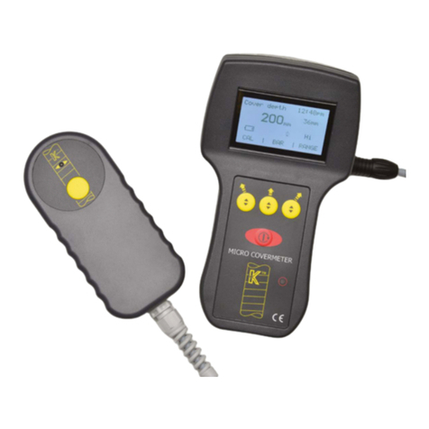
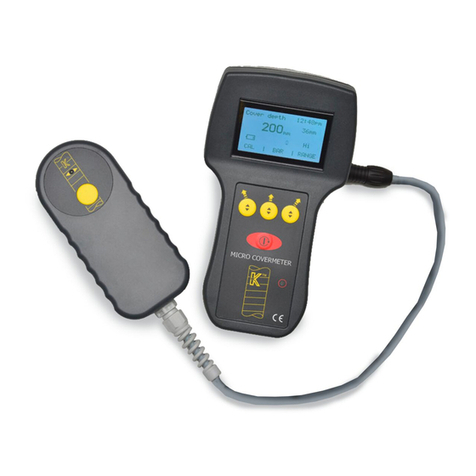
Kolectric 8020 User manual

INSTRUCTION
MANUAL
Micro Covermeter 8020
1. UNPACKING
On receipt of your new Micro Covermeter 8020 ( MC 8020 )
unpack carefully and examine items for any possible transit
damage. Any such damage should be notified to your
supplier and carrier immediately.
2. EQUIPMENT
The following items are included in the specially designed
Carry Case.
Micro Covermeter 8020 instrument with integral re-
chargeable battery.
Shoulder harness and wrist strap.
AC/DC adaptor for battery charging, with cable and
connector.
Probe
Spacer
Connection cable
Download cable and software
Earphone
On-site charger *
* If specified at time of order.
On receipt it should be noted that the on-board battery has
approximately 20% of a full charge available which will be
sufficient to enable the function check described below to
be carried out. However, prior to first time use in the field, it
is necessary to fully charge the unit.
Kolectric Research Limited
Couching House, Couching Street
Watlington, OX49 5PX United Kingdom
Tel: +44 (0) 1491-613523
Fax: +44 (0) 1491-613339
www.kolectric.com
KOLECTRIC
1
CONTENTS
1. UNPACKING
2. EQUIPMENT
3. OPERATION
4. SETTING UP A NEW INSTRUMENT
5. SWITCH ON AND GO
6. AUTOMATIC BAR SIZING
7. PROBE SEARCHING METHODS
8. SPECIFICATION OF PROBE
9. BATTERY
10. CHARGING
11. LOW COVER ALARM MODE
12. DATA LOGGING
13. DOWNLOADING TO A PC
14. ON-SITE POWER SUPPLY **
15. EARPHONE
** OPTIONAL EXTRA
Page
1
1
2
4
9
11
12
13
14
15
15
16
17
17
17

3. OPERATION
Basic operation and function check.
Connect the K9 Probe.
There are sockets fitted either side of the hand grip and it will
be noted that the socket configurations are different. It will
only be possible to attach the Probe to the correct socket.
Having pushed the connector home, the outer ring of the
connector is rotated to lock the plug to the socket.
Press the red Mode key which has the international ON
symbol surrounded by a circular arrow. This key both turns
the unit ON and OFF (with a longer key press) and also
cycles through the display screens. On pressing this key
there will be a high pitched sound and the screen will light up
with the first display which will show the instrument name
"MC 8020", together with a software version number and the
serial number of the instrument. Verify that the serial number
corresponds with the number quoted on the delivery note
and advise your supplier in case of any discrepancy.
FIRST SCREEN DISPLAY
MC 8020
Software version
Serial number
After this display the screen display below will be shown
automatically within a few seconds.
Hold the K9 Probe in air well away from any metallic object,
and out of any magnetic field from, say, a fluorescent light or
computer screen, and press the left hand yellow 'Softkey'
button positioned under the word "CAL" on the display
screen. The display will change to the sample below. At the
time that the key is pressed there will be a high-pitched
sound, and after the calibration process has been carried out
by the instrument there will be a second, confirming, sound.
(Please note that on every key press the instrument will
indicate acceptance of the command by sounding and where
a calculation or other task is being carried out there will be a
second sound to confirm that such task has finished. The
following text excludes further mention of these sounds.)
Press the Mode key again and you will come to the Data log
screen
Press the Mode key again and you will arrive at the Main
menu screen. The reason for passing through these opening
screens before arriving at the Main Menu is that, once set up,
you will wish most often to be able to SWITCH ON & GO
(see section 5 ) without requiring to do any further setting up.
Now bring the K9 probe towards a metallic object and note
that the display changes from 200* to a smaller number. If the
metallic object is suitably large you will note that the display
may reach 0. At the same time the smaller numbers, below
and to the right of the main depth number, will increase from
0 to possibly, a five figure number such as 16000. This is the
signal strength display and it will be discussed later.
*see later section 5. Switch on & Go
This simple test will have enabled you to confirm that the
instrument is functioning. You will see a battery outline above
the word CAL and there may be some portion not "blacked
out". This denotes that the battery will need charging before
the instrument is used in the field. You may now switch the
instrument OFF by pressing the Mode key and holding this
down for about two seconds. A shorter key press will just
cycle you to the next available screen. If this happens press
again for two seconds and the unit will switch OFF. You may
switch the instrument OFF when in any screen. The
instrument will switch itself OFF if there has been no key
press for 10 minutes in order to conserve battery life. If this
happens during use you must press the Mode key in order to
bring the unit back into operation.
4.SETTING UP A NEW INSTRUMENT
It will now be advisable to set up the instrument with the
correct date and time, and also to put into the memory the set
of instructions for bar size etc., that most closely suits your
local environment and testing requirements.
Turn the instrument ON by pressing the Mode key. After the
opening screen and then the basic CAL screen have
appeared, press the Mode key again and you will come to
the Bar size screen.
Cover depth 14.17
12mm
0mm
Hi 1234
CAL BAR Hi-Lo
PRE-CALIBRATION DISPLAY (TYPICAL)
DISPLAY AFTER CALIBRATION (TYPICAL)
2
45
3
Bar size 14.17
0mm
SIZE
BAR SIZE SCREEN
Data log 14.17
Cover
Bar Date
Time
Log no
DATA LOG SCREEN
MAIN MENU SCREEN
SELECT
Main menu
Measurement Menu
Data Log Menu
Audio Menu
Date and Time Menu
Cover depth 14.17
12mm
200mm
Hi 1234
CAL BAR Hi-Lo

Now select the Audio Menu
This mode will allow the option of having the Audio tone
turned off, or working whilst performing basic cover surveys,
or having the alarm function when in the Low Cover Alarm
mode (see later chapter)
Volume can be modified between a figure of 0 and 20 and
the noise level increases as the numbers cycle through the
display when the Select button is held down.
The final option on the Main menu is the Data log Menu
The Overwrite function when ON allows the unit to overwrite
earlier logged readings when the memory becomes full. If
the Overwrite function is switched OFF then the data
logging will cease when the memory is full and these
readings will have to be downloaded to PC to enable space
to be freed up.
Clear log completely clears the Data log memory and thus if
the Clear log line is highlighted and the middle Softkey is
pressed, then the Go symbol will change to Sure?. A
second press will then delete all logged readings. If you do
NOT wish this to happen, then press the Mode key to exit
from this screen. When returning to the same screen it will
be seen that the Clear log message has reverted to Go.
5. SWITCH ON & GO
Measuring cover - manual bar selection
Connect the K9 Probe and switch on as described earlier.
Perform the calibration process. Note that the basic CAL
operation should be repeated before deep cover
measurements, and also at regular intervals anyway. If you
have already selected the units in which you are likely to be
working as recommended in section 4, then you may
commence searching for rebars. Identify the normal working
face of the Probe and explore the concrete surface. In
correct use the circular keypad with the yellow 'LOG' button
will be on top. The yellow baseplate will wear in use to
The left and right hand Softkeys have the same function of
moving the highlight to the desired line and the Right Facing
Arrow above the middle Softkey will enable each line to be
modified to the desired word or number. The time format is
either 12 or 24 hour clock. The date format is either
day/month/year (d/m/y) or month/day/year (m/d/y).
One further press of the Mode key returns you to the Main
menu where you should now highlight the Measurement
Menu. The screen display will now be as below
By default the cover units will be in mm. If this is as required
then you may change the bar size to the known or an
estimated bar size prior to commencing scanning. You may
use the automatic routine to determine the bar size when
scanning and thus may forego making any change at this
time. If the cover units have been selected to be in mm then
the bar size and low cover settings will automatically be
shown in mm.
If the cover units have been set to inches then the low cover
setting changes to inches also. When in inch setting the bar
size will be shown as a number between 0.2 and 1.6 inches.
If you toggle between inches and mm you will see that the
nearest mm bar size will be selected to the inch size entered
and vice-versa.
The final cover units selection is an 0-1000 scale available
for situations where the customer has set up his own table of
depths to suit special requirements such as the checking of
large diameter pipes or other pre-fabricated items.
The low cover setting is to activate the alarm at a preset
depth and is used in conjunction with the audio menu to
switch on this function. More information in section 11.
The final option on this screen is to turn on and off the
backlight function. This is a power hungry feature and should
only be used where the ambient light conditions demand. The
backlight may remain on when the unit has switched to
power save mode. After the unit has been switched off
manually, the backlight feature defaults to 'off'.
Pressing the right hand yellow 'Softkey' button above which
can be seen on the display the icon of an inverted triangle,
you will see that the highlighted bar moves down the menu.
Using the left hand side Softkey above which is the icon of a
triangle, the highlighted bar moves up the screen. Use these
Softkeys to highlight the Date and Time Menu and press the
middle Softkey, marked "SELECT" on the display. This will
bring up the Date and Time Menu screen.
6
89
7
DATE AND TIME SCREEN
Date and Time menu
Time fmt
Hour
Minute
Second
Date fmt
Year
Month
Date
MEASUREMENT MENU SCREEN
Measurement Menu
Bar size 12
Cover units mm
Low cover 50
Backlight off
AUDIO MENU SCREEN
Audio menu
Mode
Volume
DATA LOG SCREEN
Data log menu
Overwrite
Clear log

eventually show white. At this stage the stick-on baseplate
should be replaced to prevent damage to the probe housing
which may reduce the IP65 rating.
The Probe is correctly aligned over the rebar when the depth
reading is nearest to zero, or the tone of the Audio is at its
highest pitch if this function is switched on. The smaller
numbers referred to earlier as the signal strength may also
be noted and can be used to obtain a very precise
positioning of the probe. Note that at any time the size of the
bar being displayed on the screen can be changed by
pressing the middle Softkey above which is the word BAR.
If Data logging is taking place then when a strongest reading
is found, using the signal strength, indicating that the probe is
above the bar and positioned parallel with the axis of the bar,
then the yellow button on the K9 probe is pressed. At this
moment a floppy disc symbol will be displayed on the screen
above the Hi-Lo indicator to confirm that a reading has been
committed to the data log memory.
When the instrument leaves the factory it is usual that the
default setting of Hi will have been set and thus at CAL the
depth 200mm will be shown with the probe in air. If this has
been changed then the Lo setting will be indicated with a
reading of 120mm after CAL and with the probe in air. It must
be remembered that the last settings prior to the instrument
being switched off will remain in the memory and will be the
default settings until changed by the operator. The Hi-Lo
setting key can be selected at any time to enable the
searching to be refined to your requirements. It is not
necessary at this time to perform a further CAL. However it is
advisable to CAL whenever an important measurement is to
be made. The instrument calibrates both ranges in
succession and this can be noted on the display.
The K9 probe has a small red LED in the keypad. It will be
seen that this activates after the top dead centre of a bar
has been passed and the probe is moving away from the
bar. It can be used to aid the identification of the exact
position of the bar, though bars at the greater depths will not
act upon this feature as well as bars closer to the surface.
This LED feature taken together with the signal strength
reading and the depth display will be the best combined
method of locating a bar.
6. . AUTOMATIC BAR SIZING
During normal operation one press of the mode key will
bring up the bar size screen. Having used the previously
discussed searching techniques to locate the direction and
centre line of the bar you may now press the middle softkey
under the word Size and the instrument will perform an
automatic routine to estimate the size of the target bar. An
indication that the instrument is performing the calculation is
given and, providing always that an error message is not
shown, then a revised bar size will be displayed on this
screen accurate to one decimal point. Moving back to the
cover depth screen you will note that the bar size has been
up-dated to a whole number.
Errors that might be indicated will be that the bar being
targeted is either too near or too far for an accurate bar size
determination to take place.
7. PROBE SEARCHING METHODS
The K9 Probe is placed on the surface to be examined with
the circular keypad on the opposite face to that applied to
the surface, and thus visible. It is most convenient to have
the lead coming out of the Probe towards the operator so
that it lies under the wrist. The K9 Probe can then be moved
about on the surface until a reading is obtained. It is
recommended that the Hi setting be selected in order that
any bars within the range of the K9 probe may be detected.
When performing automatic bar sizing it may be found
desirable to change to the Lo setting to obtain a satisfactory
result. Then the Probe is rotated at this point until the
reading in the display is at the lowest number possible
(nearest to zero) which will indicate that the Probe is now
aligned with its longest face over the bar and with the bar
centrally positioned During the searching procedure
additional help can be obtained from either the pitch of the
audio if this feature has been selected, or by noting the
signal strength numbers arriving at the largest number when
directly over the bar and falling off towards zero when the
bar is passed. The red LED on the probe will also signal
when the top dead centre of the bar has been passed by
giving a brief indication as the probe moves away. On
sweeping back over the bar the LED again gives an
indication as the probe moves away, this time in the
opposite direction. Mark the point at which the indicators
suggest the top dead centre of the bar and now move the
probe along this axis to confirm the position of the bar.
Deflections may be found at points where bars at, say, 90
degrees are found. Mark these points for a later
examination. Now look for bars running parallel to the first
bar and gradually a grid can be drawn of the reinforcement.
10
12 13
11
8. SPECIFICATION OF K9 PROBE
Range 6mm bar 5 - 108 mm
40 mm bar 22 - 185 mm
Measurement is to the bar surface,
ignoring ribs
Accuracy 1mm up to60 mm
2mm up to 120 mm
3mm up to 160 mm
4mm above160 mm
Display Metric display is in whole millimetres.
Imperial display is in inches with 10ths
displayed.
Cover range 8mm to 22 mm minimum dependent on
for bar size bar diameter, although this can be
calculation overcome by the introduction of any spacer if
the bar is too close to the surface of the
concrete.
Bar size resolution is to 0,1 mm
6 mm bar - 60 mm maximum
40 mm bar - 80 mm maximum
Bar resolutionBar spacing resolution is dependent on bar size
and cover. Some examples of resolution
Performance
Bar diameterCoverMinimum bar spacing
16mm 60mm 70mm
16mm100mm110mm
25mm 130mm 150mm

Selection of Low Cover Alarm Mode
The function is selected in the Audio Menu on the Mode line.
pressing the middle Softkey will cycle the display between
OFF, COVER and LOW COVER. The depth is selected in the
Measurement menu under Low cover. Depths between 10 -
100 mm may be entered If inches are selected then the
depths will be shown in increments of 0.05 ins. Pressing and
holding the middle Softkey will cycle the numbers whilst
individual key presses will increment the number by one unit.
12. DATA LOGGING
Method of operation.
Access the Cover depth screen and locate the bar as
described above. Whilst over the bar (or in the orientation
desired) press the yellow button on the K9 probe. A symbol of
a floppy disc will be shown briefly to confirm that this reading
has been added to the memory. To confirm this you may now
press the Mode key twice to enter the Data log screen. The
last measurement logged will be visible on the screen. You
may move backwards through the saved Logged
measuements by pressing the right hand Softkey and then
back up through the sequence by pressing the left hand
Softkey.
You will note that the following pieces of information have
been stored
Cover
Bar size
Date
Time
Log number.
Performance characteristics
The instrument is fully stabilised against battery voltage
reduction until close to the point of exhaustion. A warning light
on the front face of the instrument and showing through a small
red outlined circle, will indicate when the unit should be switched
off in order to conserve any readings which have been
committed to the Data log memory.
10. CHARGING
The AC/DC adaptor supplied has a connector which it will be
seen attaches to the opposite socket to the one to which the
Probe is fitted. Push home and connect to the mains supply. The
MC 8010 should preferably be switched off during the charging
process as shortly after charging commences the symbol of the
battery will become "full" and you may remove the charger too
soon. If this happens you will see the battery symbol quickly
show that a full charge has not yet been achieved.
11. LOW COVER ALARM / QUICK SCAN MODE
Function
This mode allows a cover value to be entered into the memory.
When a Quick Scan is made over the area under test an audio
alarm will sound when the reinforcement is found closer to the
surface than the preset value. The cover at which such
reinforcement is found is shown in the display. Approximately
one square metre can be scanned in one minute in this mode.
When the memory becomes full you will find that the oldest logged
measurement is overwritten if this function has been selected in the
Data log menu. The Logged results can be downloaded to a PC
using the Download cable which connects in place of the Probe.
13. DOWNLOADING
Install the supplied software and follow the instructions
14. ON-SITE POWER SUPPLY **
This optional extra enables the operator to carry on working with
MC 8020 after the on-board power supply has been exhausted.
The unit is connected to the MC 8020 via the same socket as the
normal mains charger.
15. EARPHONE
This enables the operator to utilise the audio function of the MC
8020 when in a noisy working environment.The earphone is
connected to the MC 8020 via the charging / accessory socket.
NB The operator should take care to ensure that when using
the earphone a safe volume level is maintained.
Bar sizing 0,5 mm to 1,5 mm dependent on bar
accuracy size and cover depth under ideal
circumstances. Error codes indicate to the
user if there is too much or too little cover
for a bar size to be estimated. Otherwise
the bar size is indicated and the current
bar size used by the unit to estimate cover
is updated automatically.
FerrousFerrous concrete effects are fully
aggregates compensated for and cause no
significant errors.
Search method By reference to the screen display, the
LED indicator on the K9 probe or by use
of the Audio function.
9. BATTERY
The instrument contains a rechargeable battery which is not
user serviceable or user interchangeable. When correctly
charged the unit will give in excess of 20 hours operating life in
normal temperatures.
Battery indication.
A symbol visible in the standard Cover depth display shows the
approximate state of the battery, and the AC/DC adaptor
supplied should be used to keep the battery as fully charged
as possible to reduce the likelihood of finding that whilst on site
the unit fails because of a low battery. This unit works from
100-240 AC Volts and can therefore be plugged into a 110
volts supply, for example from an on-site generator.
14
16 17
15
Table of contents
Other Kolectric Measuring Instrument manuals