Komatsu PC18MR-3 User manual

OPERATING WEIGHT
PC18MR-3 1,780 kg 3,920 lb
PC20MR-3 2,155 kg 4,750 lb
PC27MR-3 2,890 kg 6,370 lb
PC30MR-3 3,140 kg 6,920 lb
PC35MR-3 3,575 kg 7,880 lb
PC45MR-3 4,755 kg 10,480 lb
PC55MR-3 5,160 kg 11,380 lb
COMPACT
HYDRAULIC EXCAVATOR
PC18MR-3 PC20MR-3
PC27MR-3 PC30MR-3
PC35MR-3 PC45MR-3
PC55MR-3

COMPACT HYDRAULIC EXCAVATOR MR-3 SERIES
3
MR-3 SERIES COMPACT HYDRAULIC EXCAVATOR
2
WALK-AROUND OPERATING WEIGHT
PC18MR-3 1,780 kg 3,920 lb
PC20MR-3 2,155 kg 4,750 lb
PC27MR-3 2,890 kg 6,370 lb
PC30MR-3 3,140 kg 6,920 lb
PC35MR-3 3,575 kg 7,880 lb
PC45MR-3 4,755 kg 10,480 lb
PC55MR-3 5,160 kg 11,380 lb
Photo may include optional equipment
Performance and Versatility
• Komatsu HydrauMind hydraulic system
• Automatic load sensing two-speed travel
• Standard auxiliary hydraulics
• Integrated counterweight and tight tail swing
Service and Maintenance
• Wide opening engine hood and side covers
• Side-by-side radiator and oil cooler are easy to inspect and clean
• Extended lubrication and engine oil replacement intervals reduce maintenance and down time
• Tilt-forward operator’s station provides full access to engine
Operator Comfort
• Large operator platform
• Fully adjustable suspension seat
• Pilot proportional joystick controls
• Large monitor panel
• Easy entry and egress
• Low noise
Value, Durability, and Strength
• High strength X-track frame
• Castings are used for boom foot, tip, and swing yoke
• Single large diameter swing pin
• Three track options: rubber, steel, and Roadliner
• O-ring face seal hydraulic fittings
• Moisture/dust resistant electrical connectors
General Features
• Two-post ROPS canopy or ROPS cab
• Neutral engine start system
• Excellent visibility enhances job site awareness
• Low emission Komatsu engine with dual element air cleaner
• One key operates the ignition and all machine locks

3m 10'
Rating at max. reach
Max. drawbar pull
PC55MR-3
Auxiliary flow
PC55MR-3
PC55MR-3
Max. digging height
Max. digging depth
Max. digging reach
at ground level
Loading height
PC55MR-3
COMPACT HYDRAULIC EXCAVATOR MR-3 SERIES
5
MR-3 SERIES COMPACT HYDRAULIC EXCAVATOR
4
PRODUCTIVITY FEATURES
Tight Tail Swing
Operator is able to focus on the work in front of them and
worry less about a rear swing impact, even in confined areas
with only an 80mm 3" projection over the tracks.
Confined Job Site
Advantage
Operator can focus on digging
and improve productivity,
because they can worry less
about obstacles to the rear of the
machine, such as parked cars,
walls and trees.
PC18MR-3 2,070mm 6'9"*
PC20MR-3 2,250mm 7'5"*
PC27MR-3 2,515mm 8'3"*
PC30MR-3 2,415mm 7'11"*
PC35MR-3 2,550mm 8'4"*
PC45MR-3 2,830mm 9'3"*
PC55MR-3 2,800mm 9'2"*
* : When boom swing
CLSS HydrauMind Hydraulic System
When two or more actuators are operated simultaneously,
the pressure-compensated CLSS system ensures each
actuator works according to its control input, regardless of
the size of the load. This gives the operator precise control
at all times.
2,365mm
2,365mm
2,540mm
2,800mm
2,800mm
Working Ranges
Digging Force
Automatic Two-speed Travel
The travel speed selector switch installed on the blade control
allows the operator to
engage high speed trav-
el. Once engaged the
system automatically
senses he travel load
and shifts between high
speed and low speed
travel.
Stability
The MR-3 series offers exceptional lifting capacity and stabil-
ity in a tight tail machine.
Auxiliary Flow
Max. digging reach
Max. digging depth
Loading height
Max. digging height
at ground level
Max. digging height
Max. digging depth
Max. digging reach
at ground level
Loading height
PC27MR-3
mm ft.in.
Max. crowd force: Arm
Max. digging force: Bucket
kg lb
Drawbar Pull
Lifting capacity comparison
The conditions of this comparison are a standard arm, sideways, blade on
ground, and at a height of 0m (ground level).
W
Max. reach
5000 16'5"
3110 10'2"
5170 17'0"
1805 5'11"
PC35MR-3
PC18MR-3 PC30MR-3
PC45MR-3
PC45MR-3
2100 4630
3050 6720
PC35MR-3
PC27MR-3
PC18MR-3 PC30MR-3
Auxiliary flow
ltr/min USgal/min
PC45MR-3
70 18.5
PC35MR-3
PC27MR-3
PC18MR-3 PC30MR-3
Max. drawbar pull
kg lb
PC45MR-3
3400 7500
PC35MR-3
PC27MR-3
PC18MR-3 PC30MR-3
3m 10'
Rating at max. reach
kg lb
PC45MR-3
580 1280
345 760
PC35MR-3
PC27MR-3
PC18MR-3 PC30MR-3
3615 11'10"
2160 7'1"
3935 12'11"
1220 4'0"
1010 2230
1620 3570
35 9.2
1700 3750
220 480
185 410
Expandable undercarriage (PC18MR-3)
The PC18MR-3 can pass through narrow space due to nar-
row width and undercarriage can be expanded for good sta-
bility during excavation.
1280mm
"
expanded
990mm
!!
reduced
PC55MR-3
5515 18'1"
3350 12'0"
5575 18'3"
1945 6'5"
4480 14'8"
2550 8'4"
4550 14'11"
1650 5'5"
5945 19'6"
3800 12'6"
6070 19'11"
1930 6'4"
4840 15'11"
2760 9'1"
4910 16'1"
1700 5'7"
2200 4850
3460 7630
1500 3310
2230 4920
2440 5380
3980 8770
1800 3970
3000 6610
70 18.5
4280 9440
50 13.2
3200 7050
70 18.5
4280 9440
70 18.5
3400 7500
995 2190
505 1110
1005 2220
435 960
370 820
245 540
365 800
220 480
PC20MR-3
4000 13'1"
2280 7'6"
4000 13'1"
1430 4'8"
PC20MR-3
1390 3065
1920 4235
Max. crowd force: Arm
Max. digging force: Bucket
PC20MR-3
35 9.2
PC20MR-3
2060 4540
PC20MR-3
285 630
240 530

7
COMPACT HYDRAULIC EXCAVATOR MR-3 SERIES
MR-3 SERIES COMPACT HYDRAULIC EXCAVATOR
6
OPERATOR ENVIRONMENT
Large Entrance and Foot Space
The two-post canopy design allows the MR-3 series to have
larger entrance for entry and egress.
Excellent Visibility
The operator’s station design allows the operator to maintain
360˚ field view.
Large Operator’s Cab (optional equipment) (not available for PC18MR-3)
The cab provides outstanding foot space. Ergonomic design helps reduce fatigue.
The large rear glass provides the operator excellent rear visibility.
Photo may include optional equipment
Upper-rail Type Sliding Door
Large Rear Glass Large-capacity Air Conditioner
(optional equipment)
(not available for PC20MR-3)
Provides comfortable operator environ-
ment throughout the year.
Photo may include optional equipment
Pattern Change Valve (optional equipment)
Pattern change
valve allows the
operator to change
easily between
ISO or SAE control
patterns.
Cup Holder
Large cup holder is standard equip-
ment.
Canopy Cab
Fully Adjustable Suspension Seat
The spacious operator’s compartment provides outstanding
ride quality. The large suspension seat enhances operator
comfort.
Joystick Controls
PPC joystick controls are low effort and provide fine control.
PC18MR-3

COMPACT HYDRAULIC EXCAVATOR
9
MR-3 SERIES
MR-3 SERIES COMPACT HYDRAULIC EXCAVATOR
8
EASY MAINTENANCE
Wide opening
Round shape design
High Strength X-track Frame
X-track frame is a large hydraulic
excavator concept and deters
dirt and debris build up
saving the operator
valuable time when
cleaning the
machine.
O-ring Face Seal
O-ring face seals are highly
reliable.
DT Connector
DT connectors are moisture
and dust resistant.
Tilt-up Operator Compartment
Operator’s compartment floor tilts forward
providing easy access to hydraulic compart-
ments.
Fully Opening Engine Door
and Side Cover
Allow easy access for daily checks and reg-
ular maintenance.
Larger Diameter Swing Pin
Has high durability and
maintains suitable clear-
ances between pin and
bushing after long-term
operation.
Photo may include optional equipment
FEATURES
Two-post ROPS & OPG Canopy
ROPS [Roll-Over Protective Structures]
This canopy meets the requirements of ROPS, with the
advantage of a two-post design.
Neutral Engine Start System
Locks out drives and hydraulics during machine start up.
Tie-Downs or Anchor Points
Large tie-downs or anchor points in the track frame and
blade allow the machine to be secured quickly for transport.
Roadliner (not available for PC18MR-3 and PC20MR-3)
Replacement is fast, easy and cost
efficient as individual shoes are
replaced when damaged or worn
instead of replacing the entire track.
Steel Shoes with
Rubber Pad
Optional Blade
(Bolt-on cutting edge type)
PA Blade (not available for PC18MR-3,
PC20MR-3 and PC27MR-3)
Blade angle
20 degrees
20 degrees
OPTIONAL EQUIPMENT

ED
B
C
A
?
@>
=
COMPACT HYDRAULIC EXCAVATOR MR-3 SERIES
11
MR-3 SERIES COMPACT HYDRAULIC EXCAVATOR
10
SPECIFICATIONS
Operating weight
PC30MR-3PC20MR-3PC18MR-3 PC45MR-3 PC55MR-3PC35MR-3
3575 7880
ROPS Canopy, Rubber shoe
21.4/2400
28.6/2400
0.11 0.14
0.10 0.13
530 21
600 24
4.8 3.0
2.8 1.7
Flywheel horse power
9
0.36 5.1
Bucket capacity
3400 7500
(SAE heaped)
(CECE heaped)
30
Bucket width
3050 6720
(incl.side cutters)
2100 4630
Travel speed
Perfomance
Komatsu 3D88E–6
Hi
Lo
Direct injection
Swing speed
1.642 100
Ground pressure
Max. traction force
12
Gradeability
58
Bucket digging force(ISO)
40
Arm crowd force(ISO)
2.3
Model
Engine
Electric
system
1740 x 355
Type
5'9'' x 1'2''
Piston displacement
Hydrostatic
Hydraulic lock type
Operation voltage
Rubber
Battery
Grease
Alternator
44 (steel)
Starter
1
Width x height
Blade
4
Variable capacity x 2
Drive method
Drive
system
gear x 1
Type of travel brake
36.1 x 2+ 19.8
Type of travel shoe
9.5 x 2 + 5.2
Adjustment of the track tension
Undercarrige
Variable capacity x 2
Number of shoes (for each side)
fixed capacity x 1
Number of carrier rollers (for each side)
265 3770
Number of track rollers (for each side)
70
18.5
Type of hydraulic pump
44 11.6
14 3.7
Max. oil flow
Hydraulic
system
6.7 1.8
Hydraulic motor
(travel)
(swing)
Max. pressure setting
Auxiliary hydraulic flow
Refilling
capacity
Fuel tank
Hydraulic tank
Engine
Coolant
kg lb
kW/rpm
HP/rpm
m3yd3
mm in
km/h MPH
km/h MPH
rpm
kg/cm2PSI
kg lb
deg.
kg lb
kg lb
—
—
ltr. in3
V
Ah
A
kW
mm ft.in.
—
—
—
—
—
—
—
—
ltr/min
USgal/min
—
—
kg/cm2PSI
ltr/min
USgal/min
ltr. USgal
ltr. USgal
ltr. USgal
ltr. USgal
3.3 0.9
4755 10480
ROPS Canopy, Rubber shoe
28.5/2400
38.2/2400
0.14 0.18
0.13 0.17
530 21
600 24
4.6 2.9
2.8 1.7
9
0.25 3.6
4280 9440
30
3460 7630
2200 4850
Komatsu 4D88E–6
Direct injection
2.189 134
12
72
40
2.3
1960 x 355
6'5'' x 1'2''
Hydrostatic
Hydraulic lock type
Rubber
Grease
39 (steel)
1
4
Variable capacity x 2
gear x 1
53.5 x 2+ 33.8
14.1 x 2 + 8.9
Variable capacity x 2
fixed capacity x 1
270 3840
70
18.5
65 17.2
20 5.3
7.5 2.0
8.5 2.2
5160 11380
ROPS Canopy, Rubber shoe
28.5/2400
38.2/2400
0.16 0.21
0.14 0.18
580 23
650 26
4.6 2.9
2.8 1.7
9
0.29 4.1
4280 9440
30
3980 8770
2440 5380
Komatsu 4D88E–6
Direct injection
2.189 134
12
72
40
2.3
1960 x 355
6'5'' x 1'2''
Hydrostatic
Hydraulic lock type
Rubber
Grease
39 (steel)
1
4
Variable capacity x 2
gear x 1
53.5 x 2+ 33.8
14.1 x 2 + 8.9
Variable capacity x 2
fixed capacity x 1
270 3840
70
18.5
65 17.2
20 5.3
7.5 2.0
8.5 2.2
1780 3920 2155 4750 3140 6920
ROPS Canopy, Rubber shoe
11.2/2600
15/2600
0.044 0.058
0.04 0.052
400 16
450 18
4.3 2.7
2.3 1.4
8.9
0.32 4.6
1700 3750
30
1620 3570
1010 2230
Komatsu 3D67E-2
Swirl chamber
0.778 47
12
41
40
1.2
990 or 1280 x 250
3'3'' or 4'2''x 10''
Hydrostatic
Hydraulic lock type
Rubber
Grease
35 (steel)
0
3
Variable capacity x 1
gear x 1
41.6 x 1+ 12.7
11.0 x 1 + 3.4
Variable capacity x 2
fixed capacity x 1
235 3340
35
9.2
19 5.0
15.2 4.0
3.3 0.9
3.1 0.8
ROPS Canopy, Rubber shoe
15.5/2500
20.8/2500
0.066 0.086
0.06 0.08
430 17
500 20
4.6 2.9
2.8 1.7
8.9
0.27 3.9
2060 4540
30
1920 4230
1390 3065
Komatsu 3D76E-6
Swirl chamber
1.115 68
12
45
40
1.4
1450 x 300
4'9'' x 1'0''
Hydrostatic
Hydraulic lock type
Rubber
Grease
39 (steel)
0
3
Variable capacity x 1
gear x 1
53.4 x 1+ 15.5
14.1 x 1 + 4.1
Variable capacity x 2
fixed capacity x 1
250 3560
35
9.2
28 7.4
19 5.0
3.4 0.9
3.0 0.8
PC27MR-3
2890 6370
ROPS Canopy, Rubber shoe
19.2/2600
25.7/2600
0.08 0.10
0.07 0.09
430 17
500 20
4.8 3.0
2.6 1.6
9.2
0.32 4.6
3200 7050
30
2230 4920
1500 3310
Komatsu 3D82AE-6
Direct injection
1.33 81
12
58
40
2.3
1550 x 355
5'1'' x 1'2''
Hydrostatic
Hydraulic lock type
Rubber
Grease
40 (steel)
1
4
Variable capacity x 1
gear x 1
70.6 x 1+ 21.4
18.7 x 1 + 5.7
Variable capacity x 2
fixed capacity x 1
250 3560
50
13.2
44 11.6
14 3.7
5 1.3
3.3 0.9
ROPS Canopy, Rubber shoe
21.4/2400
28.6/2400
0.09 0.12
0.08 0.10
430 17
500 20
4.6 2.9
2.5 1.6
9.3
0.30 4.3
3400 7500
30
3000 6610
1800 3970
Komatsu 3D88E-6
Direct injection
1.642 100
12
58
40
2.3
1550 x 355
5'1'' x 1'2''
Hydrostatic
Hydraulic lock type
Rubber
Grease
44 (steel)
1
4
Variable capacity x 1
gear x 1
69.8 x 1+ 19.8
18.4 x 1 + 5.2
Variable capacity x 2
fixed capacity x 1
265 3770
70
18.5
44 11.6
14 3.7
6.7 1.8
3.3 0.9
WORKING RANGE
LIFTING CAPACITY
Blade on ground with additional counterweight (X-weight)
Arm length
PC18MR-3
2m 6.5' 3m 10' Maximum
SideFrontSideFrontSideFront
*310 *680 235 520 *315 *700 215 470
*355 *780 *355 *780
*365 *810 230 510 *320 *710 180 400
*805 *1780 395 870
*650 *1435 420 930
*410 *900 220 480 *335 *740 185 410
*635 *1400 400 880 *340 *750 245 540
*795 *1750 390 860 *400 *880 215 470 *300 *660 165 360
3m 10'
2m 6.5'
1m 3.25'
0m 0'
–1m –3.25'
0m 0'
Arm length
PC20MR-3
2m 6.5' 3m 10' Maximum
SideFrontSideFrontSideFront
*515 *1135 375 825
*525 *1155 310 685 *545 *1200 250 550
*1310 *2885 550 1215 *685 *1510 295 650 *595 *1310 225 495
*1535 *3385 530 1170 *790 *1745 285 630 *655 *1445 240 530
*1260 *2780 545 1200 *740 *1630 345 760
*1495 *3295 515 1135 *750 *1655 275 605 *555 *1220 195 430
3m 10'
2m 6.5'
1m 3.25'
0m 0'
–1m –3.25'
0m 0'
Arm length
PC30MR-3
2m 6.5' 3m 10' Maximum
SideFrontSideFrontSideFront
*795 *1750 435 960 *825 *1820 290 640
*1000 *2200 420 930 *825 *1820 225 500
*1320 *2910 385 850 *845 *1860 210 460
*2660 *5860 680 1500 *1440 *3170 365 800 *870 *1920 220 480
*2140 *4720 695 1530 *1250 *2760 365 800 *880 *1940 275 610
*2820 *6220 670 1480 *1415 *3120 360 790 *780 *1720 185 410
3m 10'
2m 6.5'
1m 3.25'
0m 0'
–1m –3.25'
0m 0'
Arm length
PC35MR-3
2m 6.5' 3m 10' Maximum
SideFrontSideFrontSideFront
*990 *2180 *990 *2180 *1020 *2250 585 1290
*1530 *3370 1100 2430 *1060 *2340 500 1100
*2125 *4690 1025 2260 *1120 *2470 480 1060
*2610 *5750 1100 2420
*2345 *5170 995 2190 *1195 *2640 505 1110
*2245 *4950 1120 2470
*2195 *4840 995 2190 *1280 *2820 600 1320
*2735 *6030 1085 2390
*2275 *5020 980 2160 *1045 *2300 430 950
3m 10'
2m 6.5'
1m 3.25'
0m 0'
–1m –3.25'
0m 0'
Arm length
PC45MR-3
2m 6.5' 3m 10' Maximum
SideFrontSideFrontSideFront
*705 *1550 680 1500 *690 *1520 385 850
*960 *2120 655 1440 *710 *1570 315 690
*1290 *2840 610 1350 *845 *1860 335 740
*1430 *3150 580 1280 *885 *1950 345 760
*3010 *6640 1965 *4330
*1325 *2920 580 1280 *920 *2030 415 910
*1250 *2760 *1250 *2760
*1435 *3160
*850 *1870 500 1100
*2030 *4480
1140 2510 *885 *1950 440 970
*2260 *4980
1045 2300 *930 *2050 420 930
*2170 *4780
1005 2220 *985 *2170 435 960
*2205 *4860
1000 2200 *1050 *2320 500 1100
1010 2230 *895 *1970 390 860
*2790 *6150 1960 *4320
*1285 *2830 *1285 *2830
*1390 *3060 575 1270 *720 *1590 275 610
3m 10'
2m 6.5'
1m 3.25'
0m 0'
–1m –3.25'
0m 0'
965mm 3'2''
1215mm 4'0''
970mm 3'2''
1320mm 4'4''
Arm length
PC27MR-3
2m 6.5' 3m 10' Maximum
SideFrontSideFrontSideFront
*650 *1430 425 940 *695 *1530 325 720
*1215 *2680 800 1760 *795 *1750 410 900 *705 *1550 250 550
*1065 *2350 385 850 *735 *1620 230 510
*2230 *4920 680 1500 *1185 *2610 370 820 *775 *1710 245 540
*1820 *4010 695 1530 *1020 *2250 370 820 *810 *1790 315 690
*2305 *5080 660 1450 *1155 *2550 355 780 *695 *1530 205 450
3m 10'
2m 6.5'
1m 3.25'
0m 0'
–1m –3.25'
0m 0'
1100mm 3'7''
1370mm 4'6''
1240mm 4'1''
1610mm 5'3''
1370mm 4'6''
1720mm 5'8''
1375mm 4'6''
1770mm 5'10''
Arm length
PC55MR-3
2m 6.5' 3m 10' Maximum
SideFrontSideFrontSideFront
3m 10'
2m 6.5'
1m 3.25'
0m 0'
–1m –3.25'
0m 0'
1640mm 5'5''
2000mm 6'7''
*Load is limited by hydraulic capacity rather than tipping. Rated loads do not exceed 87% of hydraulic capacity or 75% of tipping load.
D
JK
B
G
FE
C
A
H
I
DIMENSIONS
A Overall length mm ft.in.
B Overall width mm ft.in.
C Overall height mm ft.in.
D Tail swing radius mm ft.in.
E Crawler length mm ft.in.
F Track gauge mm ft.in.
G Track shoe width mm in.
H/I Boom swing angle deg.
J Bucket offset LH mm ft.in.
K Bucket offset RH mm ft.in.
a Max. digging height mm ft.in.
b Max. dumping height mm ft.in.
c Max. digging depth mm ft.in.
d Max. vertical digging
depth
e Max. digging reach mm ft.in.
f Max. digging reach mm ft.in.
at ground level
g Min. swing radius mm ft.in.
(When boom swing) mm ft.in.
h Max. blade lift mm ft.in.
i Max. blade depth mm ft.in.
STD ARM WORKING RANGE
4825 15'10"
1740 5'9"
2520 8'3"
950 3'1"
2105 6'11"
1440 4'9"
300 12"
LH75/RH55
580 1'11"
770 2'6"
PC35MR-3PC30MR-3PC27MR-3PC18MR-3 PC45MR-3
5000 16'5"
3530 11'7"
3110 10'2"
2690 8'10"
5300 17'5"
5170 17'0"
2030 6'8"
(1600 5'3")
360 1'2"
390 1'3"
a Max. digging height mm ft.in.
b Max. dumping height mm ft.in.
c Max. digging depth mm ft.in.
d Max. vertical digging
depth
e Max. digging reach mm ft.in.
f Max. digging reach mm ft.in.
at ground level
g Min. swing radius mm ft.in.
(When boom swing) mm ft.in.
h Max. blade lift mm ft.in.
i Max. blade depth mm ft.in.
5270 17'3"
3790 12'5"
3455 11'4"
3120 10'3"
5640 18'6"
5520 18'1"
2140 7'0"
(1710 5'7")
360 1'2"
390 1'3"
LONG ARM WORKING RANGE
3650 12'0"
1280 4'2"
2410 7'11"
715 2'4"
1555 5'1"
1045 3'5"
230 9"
LH70/RH50
465 1'6"
785 2'7"
3615 11'10"
2610 8'7"
2160 7'1"
1785 5'10"
4025 13'2"
3935 12'11"
1670 5'6"
(1355 4'5")
280 11"
255 10"
3820 12'6"
2815 9'3"
2410 7'11"
2000 6'7"
4270 14'0"
4190 13'9"
1770 5'10"
(1435 4'8")
280 11"
255 10"
PC55MR-3
PC35MR-3PC30MR-3PC27MR-3PC18MR-3 PC45MR-3 PC55MR-3
PC35MR-3PC30MR-3PC20MR-3PC18MR-3 PC45MR-3 PC55MR-3
4480 14'8"
3190 10'6"
2550 8'4"
2080 6'10"
4650 15'3"
4550 14'11"
1980 6'6"
(1660 5'5")
360 1'2"
315 1'0"
4690 15'5"
3390 11'1"
2840 9'4"
2370 7'9"
4930 16'2"
4840 15'11"
2030 6'8"
(1700 5'7")
360 1'2"
310 1'0"
4840 15'11"
3350 11'0"
2760 9'1"
2400 7'10"
5050 16'7"
4910 16'1"
2055 6'9"
(1560 5'1")
360 1'2"
310 1'0"
5070 16'8"
3580 11'9"
3130 10'3"
2770 9'1"
5390 17'8"
5215 17'1"
2190 7'2"
(1665 5'6")
360 1'2"
310 1'0"
5515 18'1"
3785 12'5"
3350 11'0"
2645 8'8"
5735 18'10"
5575 18'3"
2340 7'8"
(1770 5'10")
430 1'5"
330 1'1"
5780 19'0"
4060 13'4"
3770 12'4"
3060 10'0"
6130 20'1"
5980 19'7"
2410 7'11"
(1860 6'1")
430 1'5"
330 1'1"
5945 19'6"
4230 13'11"
3800 12'6"
3020 9'11"
6220 20'5"
6070 19'11"
2270 7'5"
(1740 5'9")
430 1'5"
330 1'1"
6215 20'5"
4495 14'9"
4160 13'8"
3380 11'1"
6570 21'7"
6430 21'1"
2380 7'10"
(1840 6'0")
430 1'5"
330 1'1"
3750 12'4"
1450 4'9"
2520 8'3"
805 2'8"
1880 6'2"
1200 3'11"
250 9.8"
LH75/RH50
510 1'8"
760 2'6"
4560 15'0"
1550 5'1"
2520 8'3"
855 2'10"
2105 6'11"
1250 4'1"
300 12"
LH80/RH50
580 1'11"
845 2'9"
5220 17'2"
1960 6'5"
2550 8'4"
1060 3'6"
2520 8'3"
1560 5'1"
400 16"
LH85/RH50
630 2'1"
880 2'11"
5550 18'3"
1960 6'5"
2550 8'4"
1060 3'6"
2520 8'3"
1560 5'1"
400 16"
LH85/RH50
630 2'1"
880 2'11"
PC20MR-3
PC20MR-3
4000 13'1"
2760 9'1"
2280 7'6"
1860 6'1"
4150 13'7"
4000 13'1"
1790 5'10"
(1450 4'9")
340 1'1"
240 9.4"
4300 14'1"
3020 9'11"
2580 8'6"
2215 7'3"
4500 14'9"
4350 14'3"
1940 6'4"
(1515 5'0")
340 1'1"
240 9.4"
PC27MR-3
4240 13'11"
1550 5'1"
2520 8'3"
855 2'10"
1950 6'5"
1250 4'1"
300 12"
LH85/RH50
580 1'11"
845 2'9"

STANDARD/OPTIONAL EQUIPMENT
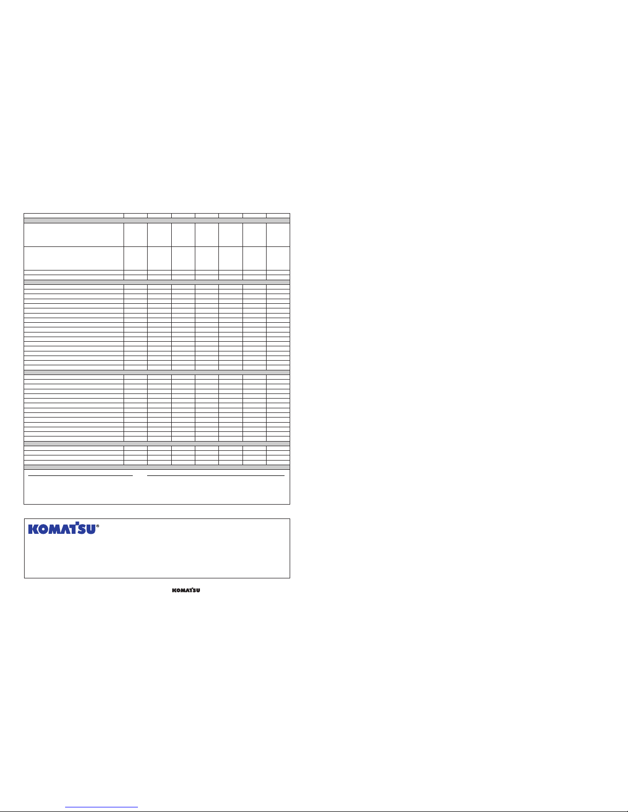
䢇: Standard equipment 嘷: Optional equipment
PC55MR-3PC45MR-3PC35MR-3PC30MR-3
Arm
PC27MR-3
STD arm with aux. piping
PC27MR: 1100mm 3'7" PC30MR: 1240mm 4'1"
PC18MR: 965mm 3'2" PC20MR: 970mm 3'2"
PC35MR: 1370mm 4'6" PC45MR: 1375mm 4'6"
Long arm with aux. piping
PC27MR: 1410mm 4'8" PC30MR: 1610mm 5'3"
PC18MR: 1215mm 4'0" PC20MR: 1320mm 4'4"
PC35MR: 1720mm 5'8" PC45MR: 1770mm 5'10"
STD arm without aux. piping
Long arm without aux. piping
Bucket Capacity Bucket width (incl. side cutters)
0.035m30.046yd3250mm 10" (320mm 13")
0.044m30.058yd3280mm 11" (350mm 14")
0.04m30.052yd3350mm 14" (400mm 16")
0.055m30.072yd3350mm 14" (420mm 17")
0.044m30.058yd3400mm 16" (450mm 18")
0.055m30.072yd3300mm 12" (370mm 14")
0.09m30.12yd3430mm 17" (500mm 20")
0.11m30.14yd3530mm 21" (600mm 24")
0.11m30.14yd3430mm 17" (500mm 20")
0.13m30.17yd3630mm 25" (700mm 28")
0.14m30.18yd3535mm 21" (600mm 24")
0.16m30.21yd3585mm 23" (650mm 26")
Track shoes
300mm 12" rubber shoes
400mm 16" rubber shoes
300mm 12" steel shoes
400mm 16" steel shoes
300mm 12" steel shoes with rubber pad
400mm 16" steel shoes with rubber pad
300mm 12" road liner
400mm 16" road liner
Blade
Blade assembly
Expandable blade assembly
Blade assembly with BOC
PAT blade
PC55MR: 1640mm 5'5"
PC55MR: 2000mm 6'7"
PC20MR-3PC18MR-3
0.033m30.043yd3250mm 10" (320mm 13")
0.022m30.029yd3300mm 12" (350mm 14")
0.044m30.058yd3350mm 14" (420mm 17")
0.066m30.086yd3430mm 17" (500mm 20")
250mm 10" rubber shoes
250mm 10" steel shoes
230mm 9" steel shoes
250mm 10" steel shoes with rubber pad
230mm 9" steel shoes with rubber pad
0.08m30.10yd3430mm 17" (500mm 20")
230mm 9" rubber shoes
0.08m30.10yd3530mm 21" (600mm 24")
Others
Standard equipment
• Additional counterweight
(PC18MR-3 and PC20MR-3)
• Air cleaner, single element
• Automatic two-speed travel
• Rear view mirrors, RH and LH
• Seat belt, 78mm 3" width
Optional equipment
• Additional working light
• Air conditioner (for cab)
(not available for PC18MR-3 and PC20MR-3)
• Cigarette lighter (for cab)
• Pattern change valve (ISO - Backhoe)
• Radiator net
• Radio (for cab)
• Steering pedals
• Rigid seat, reclining
with arm rests
• Travel alarm
• Two-post ROPS & Top
guard canopy
• Suspension seat, reclining with arm rests
• ROPS & Top guard cab
with heater, front window
washer/wiper,
cup holder and ashtray
(not available for PC18MR-3)
• Seat belt, 50mm 2" width
䢇䢇䢇䢇
嘷嘷嘷嘷
嘷嘷嘷嘷
嘷嘷嘷嘷
嘷
嘷
嘷
嘷嘷
嘷
䢇
䢇
嘷
嘷嘷
嘷
䢇
䢇
嘷
䢇䢇
䢇䢇
嘷嘷
嘷嘷
嘷嘷
嘷嘷
嘷嘷
嘷嘷
䢇䢇䢇䢇
嘷嘷嘷嘷
嘷嘷嘷嘷
䢇
嘷
嘷
嘷
嘷
嘷
嘷
䢇
嘷
嘷
嘷
䢇
嘷
䢇䢇
嘷
嘷
嘷
嘷
嘷
䢇
䢇
嘷
嘷
䢇
嘷
䢇
嘷
嘷
嘷
嘷
嘷
嘷
䢇
䢇
䢇
嘷
嘷
CEN00374-01 Materials and specifications are subject to change without notice
is a trademark of komatsu Ltd, Japan
www.Komatsu.com Printed in Japan 200906 IP.As(10)
Other manuals for PC18MR-3
3
This manual suits for next models
6
Table of contents
Other Komatsu Compact Excavator manuals