manuals.online logo
Brands
  1. Home
  2. •
  3. Brands
  4. •
  5. Komatsu
  6. •
  7. Compact Loader
  8. •
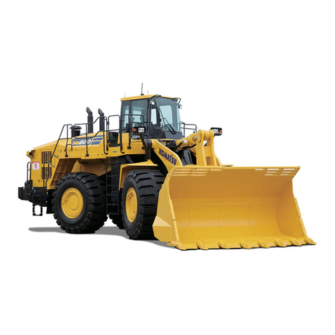
  9. Komatsu WA800-2 User manual

Komatsu WA800-2 User manual

This manual suits for next models

1

Other Komatsu Compact Loader manuals

Komatsu D475A-5 Install guide

Komatsu

Komatsu D475A-5 Install guide

Komatsu WA600-8 Manual

Komatsu

Komatsu WA600-8 Manual

Komatsu WA480-6 Manual

Komatsu

Komatsu WA480-6 Manual

Komatsu WB140-2N Manual

Komatsu

Komatsu WB140-2N Manual

Komatsu WA470-6 Manual

Komatsu

Komatsu WA470-6 Manual

Komatsu WA380-6 Install guide

Komatsu

Komatsu WA380-6 Install guide

Komatsu WA200-7 Install guide

Komatsu

Komatsu WA200-7 Install guide

Komatsu WA380-8 Manual

Komatsu

Komatsu WA380-8 Manual

Komatsu avance WB97R-2 Manual

Komatsu

Komatsu avance WB97R-2 Manual

Komatsu WB140-2N Manual

Komatsu

Komatsu WB140-2N Manual

Komatsu WA470-7 User manual

Komatsu

Komatsu WA470-7 User manual

Komatsu A96001 Install guide

Komatsu

Komatsu A96001 Install guide

Komatsu Avance WA500-3 Manual

Komatsu

Komatsu Avance WA500-3 Manual

Komatsu WA180PT-3 Manual

Komatsu

Komatsu WA180PT-3 Manual

Komatsu WA430-6E0 Install guide

Komatsu

Komatsu WA430-6E0 Install guide

Komatsu WA380-6 Manual

Komatsu

Komatsu WA380-6 Manual

Komatsu H75051 Manual

Komatsu

Komatsu H75051 Manual

Komatsu A47001 Manual

Komatsu

Komatsu A47001 Manual

Komatsu WB93R-5 Manual

Komatsu

Komatsu WB93R-5 Manual

Komatsu WA270-8 Manual

Komatsu

Komatsu WA270-8 Manual

Komatsu PC200LC-7L Manual

Komatsu

Komatsu PC200LC-7L Manual

Komatsu ecot3 HD465-7E0 Manual

Komatsu

Komatsu ecot3 HD465-7E0 Manual

Komatsu GD530A-2 Install guide

Komatsu

Komatsu GD530A-2 Install guide

Komatsu WA75-3 User manual

Komatsu

Komatsu WA75-3 User manual

Popular Compact Loader manuals by other brands

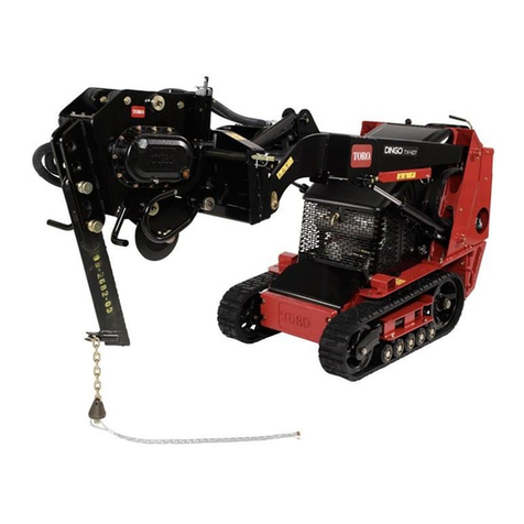
Toro TX 427 Quick start quide

Toro

Toro TX 427 Quick start quide

Kubota B2601 Operation manual

Kubota

Kubota B2601 Operation manual

Allis-Chalmers TL-16 Operator's manual

Allis-Chalmers

Allis-Chalmers TL-16 Operator's manual

Noblelift ECL15B Series Instruction handbook

Noblelift

Noblelift ECL15B Series Instruction handbook

Ballymore PLD PLUS Instruction handbook

Ballymore

Ballymore PLD PLUS Instruction handbook

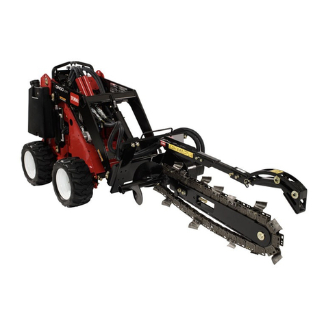
Toro 22911 Operator's manual

Toro

Toro 22911 Operator's manual

Toro 22473 Operator's manual

Toro

Toro 22473 Operator's manual

Tigercat 230C Service manual

Tigercat

Tigercat 230C Service manual

Toyota FORKLIFT 5FGIO Series manual

Toyota

Toyota FORKLIFT 5FGIO Series manual

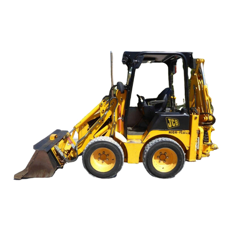
jcb 1CX Service manual

jcb

jcb 1CX Service manual

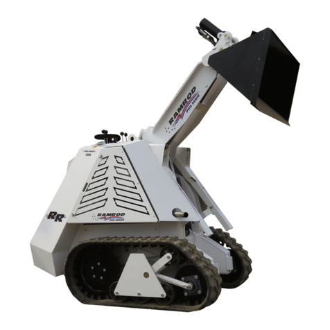
RAMROD PRO 1330 Operator's manual

RAMROD

RAMROD PRO 1330 Operator's manual

RAMROD 950 Operator's manual

RAMROD

RAMROD 950 Operator's manual

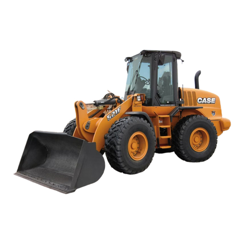
Case 521F Operator's manual

Case

Case 521F Operator's manual

Parkside 391623 2201 operating instructions

Parkside

Parkside 391623 2201 operating instructions

Worldwide Construction And Forestry Division 444K Technical manual

Worldwide Construction And Forestry Division

Worldwide Construction And Forestry Division 444K Technical manual

Case 1221F Service manual

Case

Case 1221F Service manual

jcb 135 HD Service manual

jcb

jcb 135 HD Service manual

Koyker 310 owner's manual

Koyker

Koyker 310 owner's manual

manuals.online logo
manuals.online logoBrands
  • About & Mission
  • Contact us
  • Privacy Policy
  • Terms and Conditions

Copyright 2025 Manuals.Online. All Rights Reserved.

FieldAssembly
Instruction
SEAW04280202
WHEEL LOADER
SERIALNUMBERS WA8004 -10540 andUP
This material is proprietary to Komatsu Dresser Company and is not to be reproduced, used, or disclosed except
in accordance with written authorization from Komatsu Dresser Company.
It is our policy to improve our products whenever it is possible and practical to do so. We reserve the right to make
changes or add improvements at any time without incurring any obligation to install such changes on products sold
previously.
Due to this continuous program of research and development, periodic revisions may be made to this publication.
It is recommended that customers contact their distributor for information on the latest revision.
March 1995 Copyright 1995 Komatsu Dresser Company
CONTENTS
1.
2.
3.
4.
5.
6.
7.
CHART OF SEPARATED UNITS ............................................... 3
DIMENSIONS OF SEPARATED UNITS .......................................... 3
ORDER FOR ASSEMBLY, FACILITIES TO USE, SCHEDULE FOR ASSEMBLY .......... 4
WORK SPACE LAYOUT DIAGRAM ............................................. 5
TOOLS AND EQUIPMENT TO USE ............................................. 6
PARTS LIST FOR FIELD ASSEMBLY ........................................... 14
PROCEDURE FOR FIELD ASSEMBLY .......................................... 21
Assembly processNo.
A-l Setting bare machine on supports ........................................... 21
A-2 Assembly of rear axle .................................................... 23
A-3 Assembly of front and rear drive shaft ....................................... 27
A-4 Assembly of front axle ................................................... 29
A-5 Assembly of fuel tank .................................................... 33
A-6 Assembly of ladder (Left, Right) ............................................ 41
A-7 Assembly of floor and cab assembly ......................................... 42
A-8 Assembly of floor hand rail ................................................ 52
A-9 Assembly of tire and wheel assembly ........................................ 53
A-10 Assembly of battery box assembly .......................................... 55
1OA Assembly of counterweight assembly ........................................ 60
A-l 1
A-12
A-13
A-14
A-15
A-16
M-l
M-2
M-3
M-4
M-5
M-6
M-7
M-8
M-9
Assembly of muffler pipe ................................................. 61
Assembly of lift arm assembly .............................................. 62
Assembly of front fender ................................................. 66
Assembly of front lamp assembly ........................................... 67
Assembly of ROPS canopy assembly ......................................... 68
Assemblyofbucket ...................................................... 70
Bleeding air from brake line ............................................... 74
Greasing work equipment and chassis ........................................ 75
Adjusting bucket positioner ............................................... 76
Adjusting boom kick-out .................................................. 77
Inspection of all parts .................................................... 78
Procedure for starting engine ............................................... 7g
Procedure for bleeding air from piston pump ................................... 80
Procedure for bleeding air from work equipment hydraulic circuit .................. 81
Charging air conditioner gas ............................................... 82
APPENDIX
FIELD ASSEMBLY INSPECTION REPORT
1. CHART OF SEPARATED UNITS 2. DIMENSIONS OF SEPARATED UNITS
12. ler stack.
8. Floor hand rail ass’y
6. Floor and cab ass’v ass’y
13. Fuel tank ass’y
w 5. Lift arm ass’y 16. Bare machine
‘Y
1
4. Bucket ass’y . Ladder ass’y (each) 3. Wheel and tire ass’y (each) 1. Front axle ass’y
2 Rear axle ass’y 8610 4340 1700 960
(axle support) (300) (1354) (230) (605)
3 Wheel and tire ass’y 13900 4800 2720 2720
(each 1 (3475) (1200) (2720) (2720)
4 Bucket ass’y 9485 5030 2350 2430
5 Lift arm ass’y 11090 5200 1900 1460
6 Floor and cab ass’y 950 1515 1400 1950
7 ROPS canopy ass’y 1295 1633 2330 2197
8 Floor hand rail ass’y 20 1200 1100 350
20 1400 1200 350
12 Muffler stack (2 PCS) 50 1450 520 260
13 Fuel tank ass’y i 790 2000 1900 850
14 Battery box ass’y 700 1800 1520 650
15 Counterweight 2500 I 350 3200 610
16 Bare machine 32570 I I
Total 90700
3
3. ORDER FOR ASSEMBLY, FACILITIES TO USE, SCHEDULE FOR ASSEMBLY
Assembly unit 1. Set chassison supports 1. Rear axle ass’y
2. Front axle ass’y
(front wheel and tire ass’y)
3. Front, rear drive shaft
1. Fuel tank ass’y
4. Floor handle ass’y
5. Wheel and tire ass’y
(rear wheel and tire)
* (Tighten wheel mounting
nuts to specified torque)
1. Muffler stack
2. Lift arm ass’y
* Check oil, water levels;
add oil and water
* Grease work equipment
* Charge air conditioner with
1. Front fender
2. Front lamp ass’y
3. ROPS canopy ass’y
I., Bucket ass’y
*“Adjust bucket positioner,
boom kick-out
* Check all parts for oil
Assembly Procedure No.
Maintenance (adjust-
ment) No. A-10, IOA, M-l (A-9) A-11 -A-l2
M-2 M-6 - M-9 A-13-A-15 M-3 - M-5
Air compressor
No. of workers
Forklift truck
(operator included in
number of workers
above)
5 persons
Remarks
Meeting before starting
operation,
unloading parts,
start of assembly
Remove supports Start engine Completion of assembly
4
4. WORK SPACE LAYOUT DIAGRAM
(The larger the work space is, the easier it is to carry out operations. The area shown in the diagram below (25 m x $I m)
is the minimum size needed.)
25 m
Tire and wheelass’y
Rear axle ass’y
Front axle ass’y
I72
c
5
5. TOOLS AND EQUIPMENT TO USE
1. Tools required
N
IO. Name Specification O’ty Remarks
Spanners, two-ended ring wench, box
1 Set of common standard tools wrench, cold chisel, screwdrivers, hammer, 2
adjustable wrench, hexagon wrenches, etc.
2 Power wrench 16 times
3 Power wrench 4 times
4 Socket 60 (Insertion angle; 38.1) x L: 84
5 Socket 36 (Insertion angle; 25.4) x L: 68
1 Front, rear axle mounts,
ROPS canopy mount
1 Fuel tank mount
1 For front, rear axle mount
1 For rear axle support cover, tire,
counterweight (lower)
6 Socket
7 Socket
8 Socket
9 Extension bar
IO Adapter
II Extenson bar
46 (Insertion angle; 25.4) x L: 72
55 (Insertion angle; 38.1) x L: 82
55 (Insertion angle; 25.4) x L: 82
Insertion angle: 12.7 x L: 150
Insertion angle: 19 x 12.7 x L: 55
Insertion angle: 25.4 x L: 160
1 For fuel tank, counterweight
1 ROPS mount
1 ROPS mount
1 For fuel tank
1 For fuel tank
1 For tire, counterweight,
ROPS canopy
12 Preset torque wrench (box type) 4 - 28 kgm 1 For power wrench
I 3 Interchangeable head type preset
torque wrench 6 - 14 kgm 1 For connecting hoses and tubes
,4 Interchangeable head type preset
torque wrench 2 - 4.5 kgm 1 For connecting hoses and tubes
,5 Interchangeable head type preset
torque wrench 3 - 7 kgm 1 For connecting hoses and tubes
Width across flats: 27 (insertion hole: $15) One
,6 Heads (spanner type) for inter- Width across flats: 19 (insertion hole: 912)
changeable head type preset Width across flats: 22 (insertion hole: Q12) each For connecting hoses and tubes
Width across flats: 24 (insertion hole: $12)
17 Preset torque wrench (box type) 20 - 140 kgm 1 For rear axle support cover,
counterweight
18 Preset torque wrench (box type) 50 - 210 kgm 1 For counterweight
19 Preset torque wrench (box type) 6 - 42 kgm 1 For rear axle support cover
20 Impact wrench Capacity: 1.5 - 7.5 kgm 1
21 Impact wrench Capacity: 5.5 - 31.5 kgm 1
6
40. Name
22 Impact wrench
23 Adapter
24 Adapter
25 Large hammer
26 Air grinder
27 Bars
Specification Q’ty Remarks
Capacity: 20.5 - 84.5 kgm 1 For tire, ROPS canopy
Insertion angle: 19 x 25.4 x L: 71 1 For power wrench, torque wrenc
Insertion angle: 12.7 x 9.5 x L: 41 1 For power wrench, torque wrenc
10 pounds 1
1
Large, medium, small Two Hole adjustment,
each for moving heavy things
28 Bar - 2 Hole adjustment
29 Grease gun (hand pump type) Capacity: Approx. 300 cc 1 For oiling to pin
30 Oil container Capacity: 1000 - 2000 cc 1 For bleeding air from brake line
31 Vinyl hose I.D. $6.5 - 47.0 x L: 1000 - 1500 1 For bleeding air from brake line
2. Equipment required
lo. Name Specification Q’ty Remarks
1 Truck crane 45 ton 1
2 Truck crane 30 ton 1
For comparatively
3 Forklift truck 2 unloading light
ton 1 components and parts, assembling
fuel tank
4 Compressor Capacity: 32Q I I
1 Impact wrench,
bleeding air from brake
5 Roller for moving rear axle to side I I
1 See page 10,4-6
6 Lever block 1 ton 3 For supporting cylinder,
drive shaft
7 Stand (for worker) 4 steps (approx. 1.5 m) 3 For use during operation
8 Steel sheet (t) 9x 1219x 2438 4 For positioning bare machine
7
No. Equipment Specification I I
Q’ty Remarks
9 Steel sheet (t)25 x 250 x 600 4 For positioning bare machine
10 Wooden blocks 400x400x900 14
200x400x800 4 For positioning bare machine
11 Air type grease gun Capacity: 189 1
I I
If another gas charger is used.,
12 Air compressor gas charger Charge manifold, leak detector 1 f$l;$the mstructlons supplled
13 Tester 1
I *
3. Lifting tools required
No. Name Specification Q’ty Remarks
1 Front frame lifting tool 2-point suspension (L=2250 1 See diagram below.
chain diameter=@20, sling hook=(
2 Rear frame lifting tool
3 Rear axle lifting tool
4 Nylon sling
Balanced 2-point suspension
(Chain diameter=@20, sling hook=( ’ See diagram below.
2-point suspension (L=5500
chain diameter=@1 6, grab hook(G)) ’ See diagram below.
50 x 2000 2 Axle support, cylinder sling
5 Front, rear axle lifting tool ~~~~~~~~~~~~~~~~~ook=~SL)) 1 See diagram below.
(Chain diameter=$12:5, grab hook=(G))
6 Nylon sling for drive shaft 50 x 5000 1
I I
7 Fuel tank lifting tool 2-point suspension (L=5000
chain diameter = 46.3, sling hook=( i I
2 See diagram below.
8 Floor and cab lifting tool
9 Nylon sling
10 Wire sling
2-point suspension (L=2000,
chain diameter=o6.3, sling hook=( 2 See diagram below.
150 x 10000 1 Lifting tool for tire
Capacity: 15 ton L=2500 2 Lifting tool for lift arm (lifting
Capacity: 11 ton L=2000 1 front) when removing blocks
under chassis
11 Shackle For 2 ton, 5 ton, 10 ton, 15 ton Two
each
8
[Lifting tools]
1. Front frame lifting tool
Chain diameter
2. Rear frame lifting tool
Chain diameter
20 mm i
t d
(SL)
3. Rear axle lifting tool 5. Front, rear axle lifting tool
--r
f \
‘m
Chain diameter ! \Cr
16mm \“o
i
/L
\
\
\
(G)
7.8. Fuel tank, floor and cab lifting tool
I\ i
Chain diameter,
Chain
Chain diameter
12.5 mm
(G)
9
4. Oil, grease, fuel, paint, etc.
No. Kind of fluid Specification Quantity
1 Oil . .. Brake oil SAEI OW CD IO Q
2 Molybdenum disulphide grease with (KES LM-P, SAEJBI Oa
high pressure additive NLGI: No. 1 or equivalent) 500 mQ
3 Molybdenum disulphide lithium (KES LM-G, SAEJ31 Oa
grease NLGI: No. 2 (or No. 1) or equivalent 10 Q
4 Fuel Diesel fuel As necessary
(Fuel tank: 1200 Q)
5 Paint for touching up Komatsu yellow spray can 3 cans
Komatsu blue 4 litre can
6 1Air conditioner gas / Freon gas can (400 g) 1 can
7 Window washer solvent 2 cans
All the above items except No. 4 Fuel are shiped together with the machine.
(1) Others
Roller for
Angle 50 x 50 x 850 (x 4)
5. Protective wear
Work clothes, safety boots, helmet, thick gloves, goggles, raincoat
10