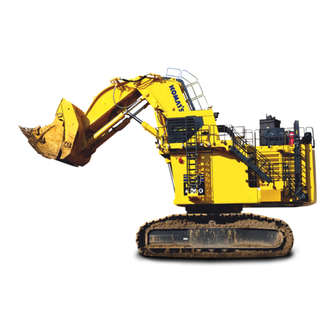
Komatsu 06253 Manual

Operation & Maintenance
Manual
PC3000-6
HYDRAULIC MINING SHOVEL
SERIAL NUMBER 06253
This material is proprietary to Komatsu Mining Germany GmbH and is not to be reproduced, used,
or disclosed except in accordance with written authorization from Komatsu Mining Germany GmbH.
It is our policy to improve our products whenever it is possible and practical to do so. We reserve
the right to make changes or add improvements at any time without incurring any obligation to install
such changes on products sold previously.
Due to this continuos program of research and development, periodic revisions may be made to this
publication. It is recommended that customer contact their distributor for information on the latest
revision.
November 2007 Copyright 2007


3
1. INTRODUCTION

1.1 CONTENTS OF THE BINDER INTRODUCTION
4
1.1 CONTENTS OF THE BINDER
Assembled in this file are the Operation-, Lubrication- and Mainte-
nance Manuals for your KOMATSU Hydraulic Mining Shovel.

INTRODUCTION 1.2 DIVISION OF THE BINDER
5
1.2 DIVISION OF THE BINDER
Part 1:
Operation Manual
Part 2:
Lubrication- and Maintenance Manual
Part 3:
Depending on the volume of Part 3 a second Binder "Volume 2" is
being delivered with the Shovel. This Binder contains the General
Assembly Procedure Manual for the Shovel, Specification Book-
let, Service Literature for the Power Unit (Diesel Engine or Elec-
tric Motor) and for Special Equipment. The Electrical- and
Hydraulic Diagrams are attached in the pocket of the front cover.
Refer to the "TABLE OF CONTENTS VOLUME 2 BINDER"
for details.
Read the Manuals before You Start the Engines.
Before operating the machine, familiarize yourself with its instru-
ments and controls.
Observe the instructions in these manuals for:
●your Personal SAFETY
●Operating SAFETY, and
●READY and EFFICIENT PERFORMANCE of your
KOMATSU Hydraulic Mining Shovel.
Periodic preventive inspections and maintenance are the surest
means of keeping the machine in proper working order. Prompt
detection and correction of minor irregularities, and immediate
replacement of worn out or broken parts will prevent failures and
avoid expenses.
Replace damaged graphics and symbols.
Observe safety precautions to prevent injury and damage.
If you have any questions concerning this literature please con-
tact
Komatsu Mining Germany GmbH
Service Information
Department 8151.40
P.O. Box 18 03 61
D - 40570 Düsseldorf
GERMANY

1.3 DESIGNATED USE OF THE SHOVEL INTRODUCTION
6
1.3 DESIGNATED USE OF THE SHOVEL
This machine has been manufactured in accordance with
advanced and up-to-date technology standards including recog-
nized safety rules. Nevertheless, its use may constitute a risk to
life and limb of the user or of third parties, or cause damage to the
machine and to other material property.
The machine must only be used in technically perfect condition in
accordance with its designated use and the instructions set out in
the operation manual. Only trained safety-conscious operators
who are fully aware of the risks involved should operate the
machine. Any functional disorders, especially those affecting the
safety of the machine, should, therefore, be rectified immediately.
The hydraulic Shovel is designed exclusively for excavating, i.e.
excavation of bulk material and natural soil structure (e.g. earth,
clay, sand and stones ashore and off-shore). Observe local and
national safety regulations. Special conditions at the worksite
require additional safe working precautions, follow your com-
pany's safety instructions. Short traveling distances for changing
the working site are considered as part of the designated use of
the Shovel.
Using the Shovel for purposes other than those mentioned above
(such as object handling and use as a transport vehicle) is consid-
ered contrary to its designated use. The manufacturer/supplier
cannot be held liable for any damage resulting from such use.
The risk of such misuse lies entirely with the user.
WARNING
Special use of the Shovel beyond its designated use, e.g.
object handling operations, require written agreement from
the manufacturer and retrofitment of the Shovel with respec-
tive safety related equipment before such special applica-
tions are permitted.

INTRODUCTION 1.4 DELIVERY OF THE SHOVEL
7
1.4 DELIVERY OF THE SHOVEL
The Shovel is being delivered disassembled into its main compo-
nents.
For assembling the Shovel refer to the separate Manual
”Assembly Procedure” in Volume 2 Binder.
WARNING
Personnel entrusted with work on the machine must have
read the Assembly Manual, the Operation,- Lubrication- and
Maintenance Manual and in particular the section on safety
before beginning work. Reading the instructions after work
has begun is too late.
If there are any questions concerning the assembling procedure,
contact your local Service Center.
Prior to first operation, inspect the Shovel thoroughly with the Ser-
vice Engineer responsible for the erection of the machine. Check
all fluid levels according to the Lubrication and Maintenance
Schedule.
Damages and defects caused by incorrect operation and mainte-
nance are not covered by the manufacturers guarantee.
N
OTICE
If the Shovel is equipped with a fire suppression system,
make sure that the system is ready for operation.
SPARE PARTS
For your spare part orders refer to the Parts Catalogue.
In order to keep your Shovel in first-class operating condition use
only genuine spare and wear parts.
The use of any part other than the genuine part releases the
KOMATSU MINING GERMANY GmbH from any guarantee.
SERVICE
For all questions related to your Shovel please contact your local
Service Center.
In all your written or phoned inquiries please indicate the model
and serial number of your Shovel.

1.5 EXPLANATION OF ABBREVIATIONS INTRODUCTION
8
1.5 EXPLANATION OF ABBREVIATIONS
ABB. Definition
A Ampere
AC Alternating Current
API American Petroleum Institute
cSt Centistoke
°C Degree Celsius
CENTRY Engine Electronic Control System
CLS Central Lubrication System
DC Direct Current
DIN German Institute for Standardization
ETM Electronic Text Monitoring System
FGPS Front Guard Protective Structure
FOPS Falling-Object Protective Structure
GL Gear Lubricant
h hours of operation
HPF High Pressure Filter
(Hydraulic Oil)
HT High Tension
LED Light Emitting Diode
LT Low Tension
MPG Multi-Purpose Grease
NNewton
Nm Newton meter
PM Planned Maintenance
ppm parts per million
PRO Protocol memory of the ETM
PTO Power Take-Off
(Pump Distributor Gear)
SAE Society of Automotive Engineers
SLS Swing circle pinion Lubrication System
STA Statistics memory of ETM
VVolt
1/min Revolutions Per Minute (RPM)

INTRODUCTION 1.6 TABLE OF CONTENTS
9
1.6 TABLE OF CONTENTS
1. INTRODUCTION...........................................................................................3
1.1 CONTENTS OF THE BINDER ........................................................................................................... 4
1.2 DIVISION OF THE BINDER ............................................................................................................... 5
1.3 DESIGNATED USE OF THE SHOVEL .............................................................................................. 6
1.4 DELIVERY OF THE SHOVEL ............................................................................................................ 7
1.5 EXPLANATION OF ABBREVIATIONS ............................................................................................. 8
1.6 TABLE OF CONTENTS ..................................................................................................................... 9
2. SAFETY ......................................................................................................15
2.1 SAFETY INSTRUCTIONS ................................................................................................................ 16
2.1.1 WARNINGS AND SYMBOLS .............................................................................................. 16
2.1.2 BASIC OPERATION AND DESIGNATED USE OF THE HYDRAULIC SHOVEL ............... 16
2.1.3 ORGANIZATIONAL MEASURES ....................................................................................... 17
2.1.4 SELECTION AND QUALIFICATION OF PERSONNEL - BASIC RESPONSIBILITIES ...... 19
2.1.5 SAFETY INSTRUCTIONS GOVERNING SPECIFIC OPERATIONAL PHASES ................ 20
2.1.6 WARNING OF SPECIAL DANGERS .................................................................................. 23
2.1.7 TRANSPORTING AND TOWING -RECOMMISSIONING .................................................. 25
2.1.8 SPECIAL SAFETY EQUIPMENT ........................................................................................ 25
2.1.9 SAFETY HARNESS IN CONFORMITY WITH EN 361 (EUROPEAN STANDARD) ........... 29
3. OPERATION ...............................................................................................37
3.1 FOREWORD .................................................................................................................................... 38
3.2 CONSTRUCTION OF THE SHOVEL ............................................................................................... 39
3.2.1 OVERALL VIEW .................................................................................................................. 39
3.2.2 UNDERCARRIAGE AND SUPERSTRUCTURE ................................................................. 40
3.2.3 HYDRAULICALLY OPERATED ACCESS LADDER ........................................................... 46
3.2.4 EMERGENCY ESCAPE LADDER ...................................................................................... 50
3.2.5 EMERGENCY ESCAPE LADDER AND ESCAPE HATCH IN THE MACHINERY HOUSE
(SPECIAL EQUIPMENT) .................................................................................................... 52
3.2.6 EMERGENCY ENGINE SHUTDOWN FROM GROUND MAN OR OPERATOR WARNING
SYSTEM .............................................................................................................................. 54
3.2.7 OPERATOR’S CAB WITH INTEGRATED FALLING OBJECT PROTECTIVE STRUCTURE
(FOPS) ................................................................................................................................ 56
3.2.8 ENGINE OIL MANAGEMENT SYSTEM ............................................................................. 64

1.6 TABLE OF CONTENTS INTRODUCTION
10
3.3 OPERATOR’S CAB - CONTROLS .................................................................................................. 72
3.3.1 CONTROLS WITH BACKHOE ATTACHMENT .................................................................. 72
3.3.2 CONTROLS WITH BOTTOM DUMP BUCKET ................................................................... 76
3.3.3 OPERATOR’S CONSOLE ................................................................................................... 81
3.4 ELECTRONIC TEXT MONITORING SYSTEM ETM ....................................................................... 88
3.4.1 INTRODUCTION ................................................................................................................. 89
3.4.2 SYSTEM COMPONENTS ................................................................................................... 93
3.4.3 FUNCTIONS OF THE ETM SYSTEM ................................................................................. 95
3.4.4 DISPLAY THE CONTENTS OF THE RECORD (PROTOCOL) MEMORY ......................... 99
3.4.5 SEVERAL MESSAGE CONDITIONS OCCUR AT THE SAME TIME ............................... 111
3.4.6 SETTINGS OF THE TEXT DISPLAY UNIT ....................................................................... 113
3.5 OPERATING THE HEATER, VENTILATION AND AIR CONDITIONING ..................................... 128
3.5.1 CONTROL MODULE FOR AUXILIARY CAB HEATER (IF SO EQUIPPED) .................... 133
3.5.2 AUXILIARY HEATER FOR OPERATORS CAB (IF SO EQUIPPED) ............................... 135
3.5.3 AUXILLIARY HEATER FOR OPERATORS CAB (IF SO EQUIPPED) ............................. 137
3.5.4 FUEL PUMP ARRANGEMENT ......................................................................................... 139
3.6 MACHINERY HOUSE .................................................................................................................... 140
3.6.1 EMERGENCY ENGINE SHUTDOWN SWITCHES .......................................................... 141
3.7 ELECTRICAL EQUIPMENT IN CAB BASE .................................................................................. 142
3.7.1 SWITCH BOX (X2) IN CAB BASE .................................................................................... 147
3.7.2 COMPONENTS OF ELECTRICAL PREHEATING SYSTEM IN CAB BASE .................... 151
3.8 PREHEATING SYSTEMS .............................................................................................................. 156
3.8.1 FOR OIL, COOLANT AND BATTERIES ........................................................................... 156
3.8.2 HEATERS FOR MACHINERY HOUSE (SPECIAL EQUIPMENT) .................................... 162
3.9 CHECKS BEFORE STARTING THE ENGINE .............................................................................. 164
3.10 STARTING THE ENGINE .............................................................................................................. 170
3.10.1 STARTING PROCEDURE ................................................................................................ 171
3.10.2 STARTING PROCEDURE AT AMBIENT TEMPERATURE UP TO -25° .......................... 173
3.11 MOVING THE SHOVEL ................................................................................................................. 182
3.11.1 TRAVEL CONTROL WITH FOOT PEDALS ...................................................................... 182
3.11.2 TRAVELLING INSTRUCTIONS ........................................................................................ 185
3.12 SLEWING AND BRAKING THE SUPERSTRUCTURE ................................................................. 186
3.12.1 SLEWING THE SUPERSTRUCTURE .............................................................................. 186
3.13 WORKING WITH THE ATTACHMENT .......................................................................................... 189
3.13.1 MACHINES EQUIPPED WITH”EURO” CONTROL SYSTEM ........................................... 189
3.13.2 MACHINES EQUIPPED WITH”KMG” CONTROL SYSTEM ............................................. 190
3.13.3 BOTTOM DUMP BUCKET ................................................................................................ 191
3.13.4 DROP BALL OPERATION ................................................................................................ 192
3.13.5 COMBINED OPERATION CYCLES .................................................................................. 195


INTRODUCTION 1.6 TABLE OF CONTENTS
11
3.14 WORKING INSTRUCTIONS .......................................................................................................... 197
3.14.1 STABILITY OF THE SHOVEL ........................................................................................... 197
3.14.2 SHOVEL OPERATION ...................................................................................................... 197
3.15 PARKING THE SHOVEL ............................................................................................................... 200
3.16 STOPPING THE ENGINE .............................................................................................................. 202
3.16.1 RELIEVE PRESSURE IN THE HYDRAULIC SYSTEM .................................................... 205
3.17 AUTOMATIC LUBRICATION SYSTEMS ...................................................................................... 206
3.17.1 OPERATION OF THE AUTOMATIC LUBRICATION SYSTEMS ..................................... 207
3.18 FIRE DETECTION AND SUPPRESSION SYSTEM ...................................................................... 210
3.18.1 HIGH LEVEL ALARM ”FIRE” ............................................................................................ 213
3.18.2 ENGINE SHUT-DOWN THROUGH FUEL SHUT-OFF SOLENOID VALVE ..................... 213
3.18.3 ACTUATION MODES OF THE FIRE SUPPRESSION SYSTEM ..................................... 213
3.18.4 INDICATION OF OPERATIONAL MODES AT CONTROL MODULE, AFTER AUTOMATIC
ACTUATION OF THE FIRE SUPPRESSION SYSTEM ................................................... 215
3.18.5 LOCATIONOFTHEEXTINGUISHINGAGENTTANKASSEMBLIESANDEXPELLANTGAS
CARTRIDGES ON POWER HOUSE ROOF ..................................................................... 217
3.19 CENTRAL REFILLING SYSTEM ................................................................................................... 218
3.19.1 SYSTEMS CONNECTED TO THE REFILLING SYSTEM ................................................ 219
3.19.2 OPERATING THE HYDRAULIC SERVICE ARM ............................................................. 221
3.19.3 RECEIVER PANEL WITH MONITOR BOX ...................................................................... 223
3.19.4 REFILLABLE GREASE CONTAINERS OF THE AUTOMATIC LUBRICATION SYSTEMS ...
227
3.20 TRANSFER PUMP FOR HYDRAULIC OIL ................................................................................... 228
3.20.1 OPERATING THE TRANSFER PUMP ............................................................................. 229
3.20.2 FUNCTIONS OF THE TRANSFER PUMP ....................................................................... 229
3.21 WORK ON THE LOADER ATTACHMENT .................................................................................... 232
3.22 TRANSPORTATION AND LIFTING OF THE
SHOVEL ......................................................................................................................................... 233
3.22.1 DISASSEMBLING OF THE SHOVEL ............................................................................... 233
3.22.2 TRANSPORTATION AND LIFTING .................................................................................. 233
3.23 RETRIEVAL PROCEDURE ........................................................................................................... 234
3.24 SHOVEL STORAGE ...................................................................................................................... 235
3.24.1 PREPARING FOR STORAGE .......................................................................................... 235
3.24.2 ONE MONTH REPETITIVE SERVICE PERIOD ............................................................... 236
3.24.3 SIX MONTH REPETITIVE SERVICE PERIOD ................................................................. 236
3.24.4 PREPARING FOR OPERATION ...................................................................................... 237
3.25 TROUBLE SHOOTING .................................................................................................................. 238
3.25.1 ENGINE ............................................................................................................................. 238
3.25.2 HYDRAULIC SYSTEM ...................................................................................................... 239
3.25.3 FINAL DRIVES AND SWING GEAR ................................................................................. 240
3.25.4 CRAWLER TRACKS ......................................................................................................... 240

1.6 TABLE OF CONTENTS INTRODUCTION
12
4. MAINTENANCE........................................................................................241
4.1 FOREWORD .................................................................................................................................. 242
4.2 PRECAUTIONS FOR MAINTENANCE ......................................................................................... 243
4.3 FLUIDS AND LUBRICANTS .......................................................................................................... 245
4.3.1 LUBRICANTS FOR OPERATION IN COLD AND ARCTIC CLIMATES ........................... 245
4.3.2 FLUIDS AND LUBRICANTS FOR MODERATE AND HOT CLIMATES ........................... 246
4.4 FILLING CAPACITIES ................................................................................................................... 248
4.5 STANDARD TORQUE LIST .......................................................................................................... 249
4.6 LUBRICATION AND MAINTENANCE SCHEDULE ...................................................................... 250
4.6.1 INITIAL SERVICING .......................................................................................................... 250
4.6.2 PERIODIC SERVICING INTERVALS ............................................................................... 250
4.6.3 PERIODIC SERVICING SCHEDULE ................................................................................ 251
4.6.4 PERIODIC REPLACEMENT OF SAFETY CRITICAL PARTS .......................................... 257
4.6.5 EXTENDED SERVICE INTERVALS FOR ENGINES WITH ENGINE OIL MANAGEMENT
SYSTEM ............................................................................................................................ 261
4.6.6 RESETTING THE ENGINE OIL BURNING SYSTEM CENTINEL .................................... 263
4.6.7 MAINTENANCE OF THE ENGINE ................................................................................... 267
4.7 WHEN NECESSARY ..................................................................................................................... 268
4.7.1 ENGINE AIR CLEANER MAINTENANCE ......................................................................... 269
4.7.2 SWING CIRCLE TOOTHING LUBRICATION ................................................................... 273
4.7.3 AUTOMATIC LUBRICATION SYSTEMS FILL GREASE CONTAINERS ......................... 275
4.7.4 TRACK ROLLERS AND GUIDE WHEELS - REPLACE FLOATING SEALS .................... 279
4.7.5 COLD STARTING AID, REPLACE FLUID CYLINDER ..................................................... 281
4.8 EVERY 10 OPERATING HOURS OR DAILY ................................................................................ 282
4.8.1 WALK - AROUND INSPECTION ....................................................................................... 283
4.8.2 AIR CLEANER - CLEAN PRE-CLEANER ......................................................................... 295
4.8.3 RADIATOR - CHECK COOLANT LEVEL .......................................................................... 297
4.8.4 TRACK GROUPS - CLEAN ............................................................................................... 297
4.8.5 FUEL SYSTEM WATER SEPARATOR - DRAIN WATER ................................................ 299
4.9 EVERY 50 OPERATING HOURS OR WEEKLY ........................................................................... 300
4.9.1 SWING GEAR AND MOTOR ADAPTER HOUSING - CHECK OIL LEVEL ...................... 301
4.9.2 TRAVEL GEARS, BRAKE HOUSINGS AND MOTOR ADAPTER HOUSINGS - CHECK OIL
LEVELS ............................................................................................................................. 305
4.9.3 PTO (PUMP DISTRIBUTOR GEAR) - CHECK OIL LEVEL .............................................. 309
4.9.4 HYDRAULIC ACCESS LADDER - CHECK SAFETY SENSOR ....................................... 311
4.9.5 HYDRAULIC OIL COOLERS - INSPECT AND CLEAN IF NECESSARY ......................... 313
4.10 EVERY 250 OPERATING HOURS OR MONTHLY ....................................................................... 314
4.10.1 AIR CONDITIONING COMPRESSOR - CHECK DRIVE BELT TENSION ....................... 315
4.10.2 RADIATOR FAN BELT AND AUTOMATIC BELT TENSIONER - MAINTENANCE CHECK ..
317
4.10.3 GENERATOR - CHECK BELT TENSION ......................................................................... 321

INTRODUCTION 1.6 TABLE OF CONTENTS
13
4.10.4 SIGNAL HORN COMPRESSOR - LUBRICATE ............................................................... 323
4.10.5 HYDRAULIC OIL COOLER FAN - CHECK CONDITION AND FASTENING ................... 323
4.10.6 AUTOMATIC LUBRICATION SYSTEMS - CLEAN IN-LINE GREASE FILTER AND CHECK
BREATHER FILTER ......................................................................................................... 325
4.10.7 CAB AIR CLEANER - CLEAN OR REPLACE FILTER ELEMENT ................................... 329
4.10.8 WINDSHIELD WASHER RESERVOIR - CHECK FLUID LEVEL ..................................... 331
4.10.9 AIR CONDITIONING FOR OPERATOR’S CAB - CHECK REFRIGERANT LEVEL ......... 331
4.11 EVERY 500 OPERATING HOURS OR MONTHLY ....................................................................... 332
4.11.1 BATTERIES - CHECK FLUID LEVEL ............................................................................... 333
4.11.2 FLEXIBLE DRIVE COUPLING - CHECK OIL LEVEL ....................................................... 335
4.11.3 FUEL TANK - DRAIN CONDENSATION .......................................................................... 337
4.11.4 CRAWLER TRACK - INSPECTION .................................................................................. 339
4.12 EVERY 1000 OPERATING HOURS OR EVERY 6 MONTH ......................................................... 344
4.12.1 HIGH STRENGTH BOLT CONNECTIONS - CHECK TORQUE LOAD ............................ 345
4.12.2 HYDRAULIC SYSTEM - FILTER SERVICE ..................................................................... 377
4.12.3 PTO (PUMP DISTRIBUTOR GEAR), SWING GEAR AND TRAVEL GEARS - OIL SAMPLE
ANALYSIS ......................................................................................................................... 391
4.12.4 SIGNAL HORN COMPRESSOR - CLEAN AND LUBRICATE .......................................... 393
4.12.5 HYDRAULIC TRACK TENSIONING SYSTEM - CHECK PRESSURE ACCUMULATORS ....
395
4.12.6 HYDRAULIC OIL COOLER - INSPECT AND LUBRICATE DOOR HINGES .................... 397
4.12.7 MACHINERY HOUSE DOORS - INSPECT AND LUBRICATE DOOR HINGES .............. 397
4.13 EVERY 2000 OPERATING HOURS OR YEARLY ........................................................................ 398
4.13.1 HYDRAULIC SYSTEM - CHANGE OIL, REPLACE SUCTION STRAINERS AND
PULSATION DAMPER ...................................................................................................... 399
4.13.2 EMERGENCY ESCAPE LADDER - INSPECTION ........................................................... 413
4.14 EVERY 3000 OPERATING HOURS HOWEVER AT LEAST ONCE A YEAR .............................. 414
4.14.1 SWING GEAR AND MOTOR ADAPTER HOUSING - CHANGE OIL ............................... 415
4.14.2 TRAVEL GEARS, BRAKE AND MOTOR ADAPTER HOUSINGS - CHANGE OIL .......... 423
4.14.3 PTO (PUMP DISTRIBUTOR GEAR) - CHANGE OIL ....................................................... 427
4.15 FIRE PREVENTION ....................................................................................................................... 430
4.16 WELD REPAIRS ............................................................................................................................ 432
4.16.1 PROTECTIVE MEASURES BEFORE STARTING WELD REPAIRS ON THE
UNDERCARRIAGE ........................................................................................................... 435
4.16.2 PROTECTIVE MEASURES BEFORE STARTING WELD REPAIRS ON THE LOADER
ATTACHMENT .................................................................................................................. 437
4.16.3 PROTECTIVE MEASURES BEFORE STARTING WELD REPAIRS ON THE
SUPERSTRUCTURE ........................................................................................................ 439
4.16.4 AFTER FINISHING THE REPAIR WELDINGS ON THE SUPERSTRUCTURE ............... 441

1.6 TABLE OF CONTENTS INTRODUCTION
14

15
2. SAFETY

2.1 SAFETY INSTRUCTIONS SAFETY
16
2.1 SAFETY INSTRUCTIONS
2.1.1 WARNINGS AND SYMBOLS
The following signs and designations are used in the manual to
designate in-structions of particular importance.
WARNING
Refers to orders and prohibitions designed to prevent injury
or extensive damage.
CAUTION
Refers to special information and/or orders and prohibitions
directed towards preventing damage.
N
OTICE
Refers to special information on how to use the machine
most efficiently.
2.1.2 BASIC OPERATION AND DESIGNATED USE OF THE HYDRAULIC
SHOVEL
Refer to "DESIGNATED USE OF THE SHOVEL" on page 6
for details.
WARNING
The use of the Shovel for object handling operations without
the respective safety related equipment is not allowed.

SAFETY 2.1 SAFETY INSTRUCTIONS
17
2.1.3 ORGANIZATIONAL MEASURES
●The Operation,- Lubrication and Maintenance Manual must
always be at hand at the place of use of the machine, e. g. by
stowing them in the box provided for such purpose.
●In addition to the Operation,- Lubrication and Maintenance
Manual, observe and instruct the user in all other generally
applicable legal and other mandatory regulations relevant to
accident prevention and environmental protection.
These compulsory regulations may also deal with the han-
dling of hazardous substances, issuing and/or wearing of per-
sonal protective equipment, or traffic regulations.
●The Operation,- Lubrication and Maintenance Manual must
be supplemented by instructions covering the duties involved
in supervising and notifying special organizational features,
such as job organization, working sequences or the person-
nel entrusted with the work.
●Personnel entrusted with work on the machine must have
read the Operation,- Lubrication and Maintenance Manual
and in particular the chapter on safety before beginning work.
Reading the instructions after work has begun is too late. This
applies especially to persons working only occasionally on
the machine, e. g. during setting up or maintenance.
●Check - at least from time to time - whether the personnel is
carrying out the work in compliance with the Operation,-
Lubrication and Maintenance Manual and paying attention to
risks and safety factors.
●For reasons of security, long hair must be tied back or other-
wise secured, garments must be close-fitting and no jewellery
- such as rings - may be worn. Injury may result from being
caught up in the machinery or from rings catching on moving
parts.
●Use protective equipment wherever required by the circum-
stances or by law.
●Observe all safety instructions and warnings attached to the
machine.
●See to it that safety instructions and warnings attached to the
machine are always complete and perfectly legible.
●In the event of safety-relevant modifications or changes in the
behaviour of the machine during operation, stop the machine
immediately and report the malfunction to the competent
authority/person.
●Never make any modifications, additions or conversions
which might affect safety without the supplier’s approval. This
also applies to the installation and adjustment of safety
devices and valves as well as to welding work on load-bear-
ing elements.
●Spare parts must comply with the technical requirements
specified by the manufacturer. Spare parts from original
equipment manufacturers can be relied to do so.

2.1 SAFETY INSTRUCTIONS SAFETY
18
●Replace hydraulic hoses within stipulated and appropriate
intervals even if no safety-relevant defects have been
detected.
●Adhere to prescribed intervals or those specified in the Oper-
ation,- Lubrication and Maintenance Manual for routine
checks and inspections.
●For the execution of maintenance work, tools and workshop
equipment adapted to the task on hand are absolutely indis-
pensable.
●The personnel must be familiar with the location and opera-
tion of fire extinguishers.
●Observe all fire-warning and fire-fighting procedures.

SAFETY 2.1 SAFETY INSTRUCTIONS
19
2.1.4 SELECTION AND QUALIFICATION OF PERSONNEL -
BASIC RESPONSIBILITIES
●Any work on and with the machine must be executed by reli-
able personnel only. Statutory minimum age limits must be
observed.
●Employ only trained or instructed staff and set out clearly the
individual responsibilities of the personnel for operation, set-
up, maintenance and repair.
●Make sure that only authorized personnel works on or with
the machine.
●Define the machine operator’s responsibilities - also with
regard to observing traffic regulations - giving the operator the
authority to refuse instructions by third parties that are con-
trary to safety.
●Do not allow persons to be trained or instructed or persons
taking part in a general training course to work on or with the
machine without being permanently supervised by an experi-
enced person.
●Work on the electrical system and equipment of the machine
must be carried out only by a skilled electrician or by
instructed persons under the supervision and guidance of a
skilled electrician and in accordance with electrical engineer-
ing rules and regulations.
●Work on chassis, brake and steering systems must be per-
formed by skilled personnel only which has been specially
trained for such work.
●Work on the hydraulic system must be carried out only by
personnel with special knowledge and experience of hydrau-
lic equipment.

2.1 SAFETY INSTRUCTIONS SAFETY
20
2.1.5 SAFETY INSTRUCTIONS GOVERNING SPECIFIC OPERATIONAL
PHASES
STANDARD OPERATION
●Avoid any operational mode that might be prejudicial to
safety.
●Before beginning work, familiarize yourself with the surround-
ings and circumstances of the site, such as obstacles in the
working and travelling area, the soil bearing capacity and any
barriers separating the construction site from public roads.
●Take the necessary precautions to ensure that the machine is
used only when in a safe and reliable state.
Operate the machine only if all protective and safety-oriented
devices, such as re- movable safety devices, emergency
shut-off equipment, sound-proofing elements and exhaust-
ers, are in place and fully functional.
●Check the machine at least once per working shift for obvious
damage and defects. Report any changes (incl. changes in
the machine’s working behaviour) to the competent organiza-
tion/person immediately. If necessary, stop the machine
immediately and lock it.
●In the event of malfunctions, stop the machine immediately
and lock it. Have any defects rectified immediately.
●Start the machine from the driver’s seat only.
●During start-up and shut-down procedures always watch the
indicators in accordance with the Operation,- Lubrication and
Maintenance Manual.
●Before starting up or setting the machine in motion, make
sure that nobody is at risk.
●Before starting work or travelling with the machine, check that
the braking, steering, signalling and lighting systems are fully
functional.
●Before setting the machine in motion always check that the
accessories have been safely stowed away.
●When travelling on public roads, ways and places always
observe the valid traffic regulations and, if necessary, make
sure beforehand that the machine is in a condition compatible
with these regulations.
●In conditions of poor visibility and after dark always switch on
the lighting system.
●Persons accompanying the driver must be seated on the pas-
senger seat provided for this purpose.
●When crossing underpasses, bridges and tunnels or when
passing under overhead lines always make sure that there is
sufficient clearance.
This manual suits for next models
1
Table of contents
Other Komatsu Construction Equipment manuals

Komatsu
Komatsu WA250-6 Install guide

Komatsu
Komatsu 830E-1AC Manual

Komatsu
Komatsu D65EX-12 Manual

Komatsu
Komatsu Super D155AX-3 Manual

Komatsu
Komatsu D155AX-5 Manual

Komatsu
Komatsu 450FXL-1 Manual

Komatsu
Komatsu WD600-3 Manual

Komatsu
Komatsu D37EXi-24 Manual

Komatsu
Komatsu D31EX-21 Manual

Komatsu
Komatsu 860E-1KT Manual

Komatsu
Komatsu Galeo BR380JG-1 Manual

Komatsu
Komatsu ecot3 WA500-6 Install guide

Komatsu
Komatsu D375A-8 Manual

Komatsu
Komatsu HD785-7 Quick start guide

Komatsu
Komatsu D85EX-18 Manual

Komatsu
Komatsu XT430-3 Manual

Komatsu
Komatsu D475A-3 Manual

Komatsu
Komatsu D85EX-15 Manual

Komatsu
Komatsu Boss D87E-2 Manual

Komatsu
Komatsu ecot 3 Manual