Kongskilde 8200 DF Series User manual

Kongskilde
8200
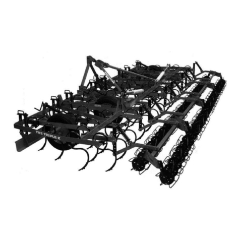
KONGSKILDE 8200 DF
Field Cultivator - Assembly/Parts
Models
768236901 8236 Field Cultivator (36.5')
768238901 8238 Field Cultivator (38.5')
768240901 8240 Field Cultivator (40.5')
768242901 8242 Field Cultivator (42.5')
768244901 8244 Field Cultivator (44.5')
768246901 8246 Field Cultivator (46.5')
768248901 8248 Field Cultivator (48.5') 760000229 - Revision 7
Serial No. 411391 - current
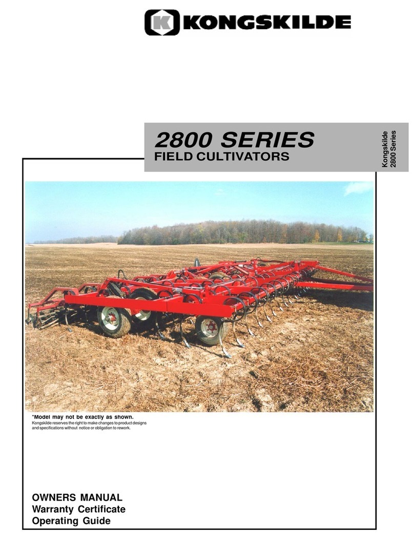
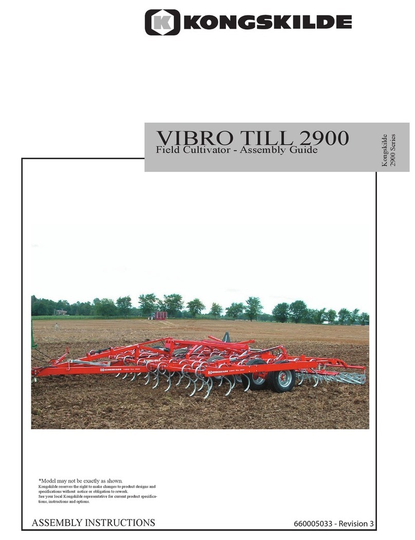
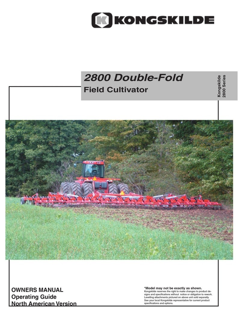
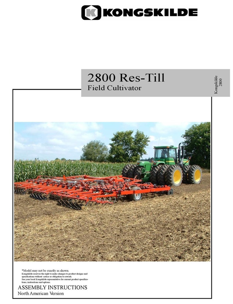
*Model may not be exactly as shown.
Kongskilde reserves the right to make changes to product designs and
specifications without notice or obligation to rework.
See your local Kongskilde representative for current product specific-
ations and options.

2
Introduction: ........................................................................................................................................3
Center Frame Assembly .......................................................................................................................4
Center Rockshaft Assembly .................................................................................................................6
Center Rockshaft Parts .........................................................................................................................8
Fold Cylinder Mount Assembly .........................................................................................................10
Center Lift Cylinders & Linkages Assembly .....................................................................................12
Single Point Assembly .......................................................................................................................14
Light Stands & Safety Locks Assembly ............................................................................................16
Hitch & Turnbuckle Assembly ..........................................................................................................18
Intermediate Wing Frame Assembly ..................................................................................................20
Intermediate Fold Cylinder Assembly ...............................................................................................22
Wing Rockshaft Assembly .................................................................................................................24
Wing Rockshaft Parts .........................................................................................................................26
Wing Lift Cylinder & Linkage Assembly ..........................................................................................28
Outer Wing Assembly ........................................................................................................................30
Outer Fold Cylinder Assembly ..........................................................................................................32
Outer Wing Rockshafts and Linkages ................................................................................................34
Wing Fold Stands ...............................................................................................................................34
VibroTine Assembly Option ..............................................................................................................36
C-Shank Assembly Option .................................................................................................................38
Gauge Wheel Assembly .....................................................................................................................40
Gauge Wheel Parts .............................................................................................................................42
Rear Jack Assembly ...........................................................................................................................44
Hydraulic Tree Assembly ...................................................................................................................46
Lift Hydraulics ...................................................................................................................................48
Fold Hydraulics ..................................................................................................................................50
Cylinder Parts .....................................................................................................................................52
Light Kit Assembly ............................................................................................................................54
Rear Hitch (Optional) ........................................................................................................................56
Rear Hitch Hydraulic Kit (Optional) .................................................................................................58
Rear Hitch Light Extension Kit (Optional) ........................................................................................60
Decal Placement .................................................................................................................................62
Assembly Completion ........................................................................................................................64
Appendix A ........................................................................................................................................65
Appendix B ........................................................................................................................................68
Table of Contents

3
Introduction:
Please take the time to carefully read all the instruction booklets provided with your new
Kongskilde product. Once you are finished reading do not throw these guides out. Keep them for
later review.
These instruction booklets have been developed to assist you in assembling, adjusting and maintain-
ing your new Kongskilde Product. To obtain optimal performance over the lifetime of the product
read and follow these instructions carefully.
When the assembly of the unit is completed, please refer to the Owners Manual before attempting
to adjust or use the product. The Owners Manual will provide you with further instructions on the
proper Field Settings, Adjustments and Maintenance Procedures for Safe Operation of the unit.
If optional equipment or attachments have been ordered for your unit, please refer to the instruction
booklets provided for proper installation and adjustment of these accessories.
Please take the time to fill out and return the Owners Registration and Warranty Form provided with
the Owners Manual in order to activate the warranty coverage.
NOTES:
-Images in this manual are for reference only and may not exactly match actual components.
-This manual depicts "Left" and "Right" as if standing behind the unit facing forward.
-Refer to torque chart in Appendix B for proper tightening of bolts, unless otherwise noted.

4
Center Frame Assembly
Instructions:
-Hardware included in bag 760033040
-Connect center frames as shown, using parts listed on next page.
-Place center frames on steel shop stands during assembly until lift hydraulics are installed and
working.

5
Parts list / 8200 DF Center Frame Assembly. Date: August 2014
Fig. Part no. Qty Description
1 760032000 1 Center Mainframe Wdmt, LH
2 760032001 1 Center Mainframe Wdmt, RH
3 760032063 1 Leveling Pivot Linkage Mount
4 600356107 2 Bolt, 5/8" X 3" GR. 5
5 600356023 16 Bolt, 5/8" X 1 3/4" GR. 5
6 600366031 18 Nut, Toplock 5/8"
7 600471000 7 Grease Fitting

6
Instructions:
-Hardware included in bag 760033040
-Insert wear sleeves into rockshaft blocks before assembling rockshaft.
-Assemble rockshaft, spindles and wheels to center frame as shown, using parts listed on next
page.
-Spindles and wheels can be installed to rockshaft assembly before or after rockshaft is attached to
the frame
-IMPORTANT: Install wheels to the spindles so the wheel rims are offset toward the wheel arms
(Narrow setting). Torque lug nuts to 170 ft-lbs. Re-torque lug nuts after ten hours of field use.
Center Rockshaft Assembly

7
Parts list / 8200 DF Center Rockshaft Assembly. Date: August 2014
Fig. Part no. Qty Description
1 760033003 1 Center Rockshaft Assembly
2 760031189 8 Center Rockshaft Block
3 7600355102 8 Bolt, 3/4" X 9-1/2" GR. 8
4 600366024 8 Nut, Toplock 3/4"
5 7600473119 4 8 X 8 Hub (G60-8) & Spindle Assembly
6 600355052 4 Bolt, 5/8" X 4-1/2" GR. 8
7 600366031 4 Nut, Toplock 5/8"
8 600473108 4 Wheel Assembly 12.5L-16.5 Galaxy (8-Bolt)
9 760031190 8 Wear Sleeve Half
See following page for part details

8
Center Rockshaft Parts

9
Parts list / 8200 DF Center Rockshaft Parts. Date: April 2015
Fig. Part no. Qty Description
1 760032008 1 Center Rockshaft Wdmt
2 760032010 2 Center Tandem Wdmt
3 7600473116 4 6000# Spindle (2-3/4" x 18") w/Hole
- 7600473117 4 2-3/4" x 18" Spindle Assembly (Includes Items 3, 10, 11, 22)
4 763011289 4 8-Bolt Hub 60-8 (Includes Items 4, 7, 8, 13, 14)
- 763012379 4 8 x 8 Hub (G60-8) Assembly Complete (Includes Items 4-9, 12-14)
5 600473057 4 Seal, 2-3/4" w/Spring & Alternate Lip
6 76301131 4 Bearing - JLM506849
7 76301137 4 Bearing Cup - JLM506810
8 76301135 4 Bearing Cup - LM501310
9 76301129 4 Bearing - LM501349
10 600473052 4 Washer EMI-8000
11 600366012 4 Slotted Nut 1" - UNF
12 76301230 4 Dust Cap
13 76301235 32 5/8"-18 UNF Lug Nut
14 600471000 8 GF-641 Grease Fitting
15 760031111 4 Tandem Spacer
16 7600473113 4 Seal 22368
17 7600473115 4 Bearing Cone, Timken 2776
18 7600473114 4 Bearing Cup, Timken 2720
19 760032026 2 Tandem Pin Wdmt
20 7600366051 2 Slotted Nut, 1-1/2"-12 UNF Plated
21 600383025 2 Cotter Pin, 3/8" x 2-1/2"
22 600383003 2 Cotter Pin, 3/16" x 1-3/4"
Quantities listed are for each individual part in the complete rockshaft assembly

10
Instructions:
-Hardware included in bag 760033040
-Attach fold cylinder mounts and cross brace as shown, using hardware on next page.
Fold Cylinder Mount Assembly

11
Parts list / 8200 DF Fold Cylinder Mount Assembly. Date: August 2014
Fig. Part no. Qty Description
1 760032049 1 Rear Fold Cylinder Base Mount Wdmt
2 760032051 1 Center Frame Cross Brace Wdmt
3 760032050 1 Front Fold Cylinder Base Mount Wdmt
4 600355028 16 Bolt, 5/8" X 2" GR. 8
5 600381052 16 Flat Washer, 5/8" - SAE
6 600366031 16 Nut, Toplock 5/8"
7 600373058 8 U-Bolt, 5/8" X 4" X 5-1/2"
8 600382054 16 Lock Washer 5/8"
9 600365014 16 Standard Nut 5/8"

12
Instructions:
-Hardware included in bag 760033041
-Attach lift cylinders and linkages as shown, using parts listed on next page.
-On base end of cylinders, use pins which come with cylinders - pins shown are for repair only
-Install leveling linkage as shown in image "A". This will give the rear of the machine more trans-
port height than original setting "B".
Center Lift Cylinders & Linkages Assembly
AB

13
Parts list / 8200 DF Center Lift Cylinders & Linkages Assembly. Date: May 2015
Fig. Part no. Qty Description
1 7600474662 2* Cylinder 4 1/4” X 8” Welded Rephase - Monarch (8242, 8244, 8246, 8248)
7600474663 2* Cylinder 4" X 8" Welded Rephase - Monarch (8236, 8238, 8240)
2 760032057 2 Cylinder Linkage Wdmt
3 760032056 2 Leveling Linkage Tube Wdmt
4 600356101 2 Bolt, 1" X 5" GR. 5
5 600366032 8 Nut, Toplock 1"
6 7600383204 2 Pin 1" - 75MM
7 600381018 2 Flat Washer 1"
8 600383117 2 Ring Cotter Clip 1"
9 600356029 4 Bolt, 1" X 5-1/2" GR.5
10 7600383216 2 Spring Bushing 1"
11 760031113 2 Rockshaft Cylinder Pin
12 600356111 3 Bolt, 3/8" X 2" GR.5
13 600366028 3 Nut, Toplock 3/8"
14 760032061 1 Leveling Tube Wdmt
15 760031114 1 Leveling Link Pin
16 760032062 1 Leveling Linkage Wdmt
17 7600355110 2 Bolt, 1" X 6-1/2" GR.8 Special
18 600471000 2 Grease Fitting

14
Instructions:
-Hardware included in bag 760033016
-Assemble upright bracket and valve to frame as shown, using hardware listed on next page.
Bracket should be placed 8" from center frame rail.
-Assemble striker bolt and spring to outer tube wdmt. Insert inner tube through outer tube and
connect together with crank. Attach depth indicator to assembly.
-Insert assembly through upright bracket and connect to leveling tube.
Single Point Assembly

15
Parts list / 8200 DF Single Point Assembly. Date: August 2014
Fig. Part no. Qty Description
1 760032021 1 Single Point Upright Wdmt
2 76101322 2 U-Bolt, 3/8”-16 X 4” X 5”
3 600382051 5 Lockwasher, 3/8"
4 600365008 5 Nut, 3/8"
5 7600470491 1 Single Point Valve
6 600356148 2 Bolt, 5/16" X 2-1/2" GR. 5
7 600382050 2 Lockwasher, 5/16"
8 600365007 2 Nut, 5/16"
9 601140555 1 Striker Bolt 3/8" X 3
10 601140556 1 Striker Spring
11 600366028 1 Nut, Toplock 3/8"
12 760032022 1 Single Point Outer Tube Wdmt
13 760032038 1 Single Point Crank
14 600365009 1 Nut, 1/2"
15 7600365078 1 Jam Nut, 1/2"
16 760032023 1 Single Point Inner Tube Wdmt
17 760031121 1 Single Point Tube Spacer
18 600356007 1 Bolt, 3/8" X 2-1/2" GR. 5
19 760032027 1 Single Point Depth Indicator Wdmt
20 600381006 3 Flatwasher, 3/8"
21 600383037 1 Cotter Pin, 1/8" X 1"

16
Instructions:
-Hardware included in bags 760033041 & 760033045
-Attach light stands and safety locks to center frame.
-IMPORTANT: Light tubes should be mounted on stands as far outwards as possible on all double
fold models except the 8238. The 8238 requires the light tubes to be mounted at the narrowest
position.
-Disconnect safety pin chain from split ring and route chain through base of plates as shown be-
low. Reconnect chain to split ring to secure pin to frame.
Light Stands & Safety Locks Assembly
Safety chain routed
through plates
Model 8238
Models
8236, 8240, 8242,
8244, 8246, 8248

17
Parts list / 8200 DF Light Stands & Safety Locks Assembly. Date: August 2014
Fig. Part no. Qty Description
1 760032024 2 Light Stand Wdmt
2 7600356163 4 Bolt, 3/8" X 2-3/4" GR. 5
3 600366028 4 Nut, Toplock 3/8"
4 760032025 2 Light Tube Wdmt
5 7600373128 4 U-Bolt, 3/8" X 2" X 3"
6 600382051 8 Lockwasher, 3/8"
7 600365008 8 Nut, 3/8"
8 601140845 1 SMV Sign
9 760031216 2 4-1/4" x 8” Cylinder Safety Lock
10 600383141 2 Clevis Pin, 3/8" X 3"
11 600383142 2 Hair Pin, 3/32" X 1-1/2"
12 7600383208 2 Safety Pin w/Chain
13 - 2 Amber Flashing Light (included in Light Kit 760033006)
14 - 2 Red Tail/Brake Light (included in Light Kit 760033006)
15 600356138 8 Bolt, 1/4" X 1" GR. 5
16 600381023 16 Flat Washer, 1/4"
17 600366026 8 Nut, Toplock 1/4"

18
Instructions:
-Hardware included in bags 760033040, 760033041, 760033045 & 760033016
(The hitch and components can be installed before or after the wing frames have been assembled
to the center frame.)
-Attach hitch, turnbuckle and components to center frame as shown, using hardware listed on next
page.
-Turnbuckle should be installed with an initial pin-pin length of about 104-1/2".
Hitch & Turnbuckle Assembly

19
Parts list / 8200 DF Hitch & Turnbuckle Assembly. Date: May 2015
Fig. Part no. Qty Description
1 760032015 1 Hitch Wdmt
2 760031082 2 Hitch Pivot Pin
3 7600356163 2 Bolt, 3/8" X 2-3/4" GR. 5
4 600366028 4 Nut, Toplock 3/8"
5 760033027 1 Turnbuckle Assembly (Includes Items 22-25)
6 7600355110 1 Bolt, 1" X 6-1/2" GR.8 Special
7 760031186 1 Turnbuckle Latch
8 600381018 5 Flat Washer 1"
10 601140769 1 CAT II/III Combo Double Clevis - 2” (Includes Items 26-29)
601140770 - CAT IV Pindle Style - 2 1/4" (no clevis)
601232365 - CAT 1V/V Pindle Style - 2 3/4" (no clevis)
11 600355025 2 Bolt, 1" X 7" GR. 8
12 600355027 1 Bolt, 1" X 8" GR. 8
13 600366032 4 Nut, Toplock 1"
14 600461011 1 ASAE Safety Chain Assembly
15 760032039 1 Hydraulic Hose Support Wdmt
16 600356020 2 Bolt, 3/8" X 1" GR. 5
17 600600268 1 Manual Canister
18 600356138 4 Bolt, 1/4" X 1" GR. 5
19 600381023 8 Flat Washer, 1/4"
20 600366026 4 Nut, Toplock 1/4"
21 601231223 1 Jack TWL 190 DL-B
22 760032066 1 Turnbuckle Wdmt
23 760032064 1 Turnbuckle Clevis RH
24 760032065 1 Turnbuckle Clevis LH
25 600471000 6 Grease Fitting
26 601140771 1 CAT III Base Hitch
27 601140772 1 CAT III Clevis Insert
28 600355047 1 Bolt, 3/4" X 5" GR. 8
29 600366024 1 Nut, Toplock 3/4"
30 760031152 1 Adjustment Wrench
31 760001005 1 Socket, 7 Pin Light Plug Storage

20
Instructions:
-Hardware included in bags 760033020 & 760033043
-Bolt together wing frames as shown, using hardware listed on next page, and then attach to center
frame. Use steel shop stands to support the wings until lift and fold hydraulics are installed and
working.
-Repeat for opposite side
Intermediate Wing Frame Assembly
This manual suits for next models
7
Table of contents
Other Kongskilde Tiller manuals