Kongskilde VIBRO MASTER 3000 User manual

VIBRO MASTER 3000
Directions for use

2
Contents
Introduction......................................................................................................... 3
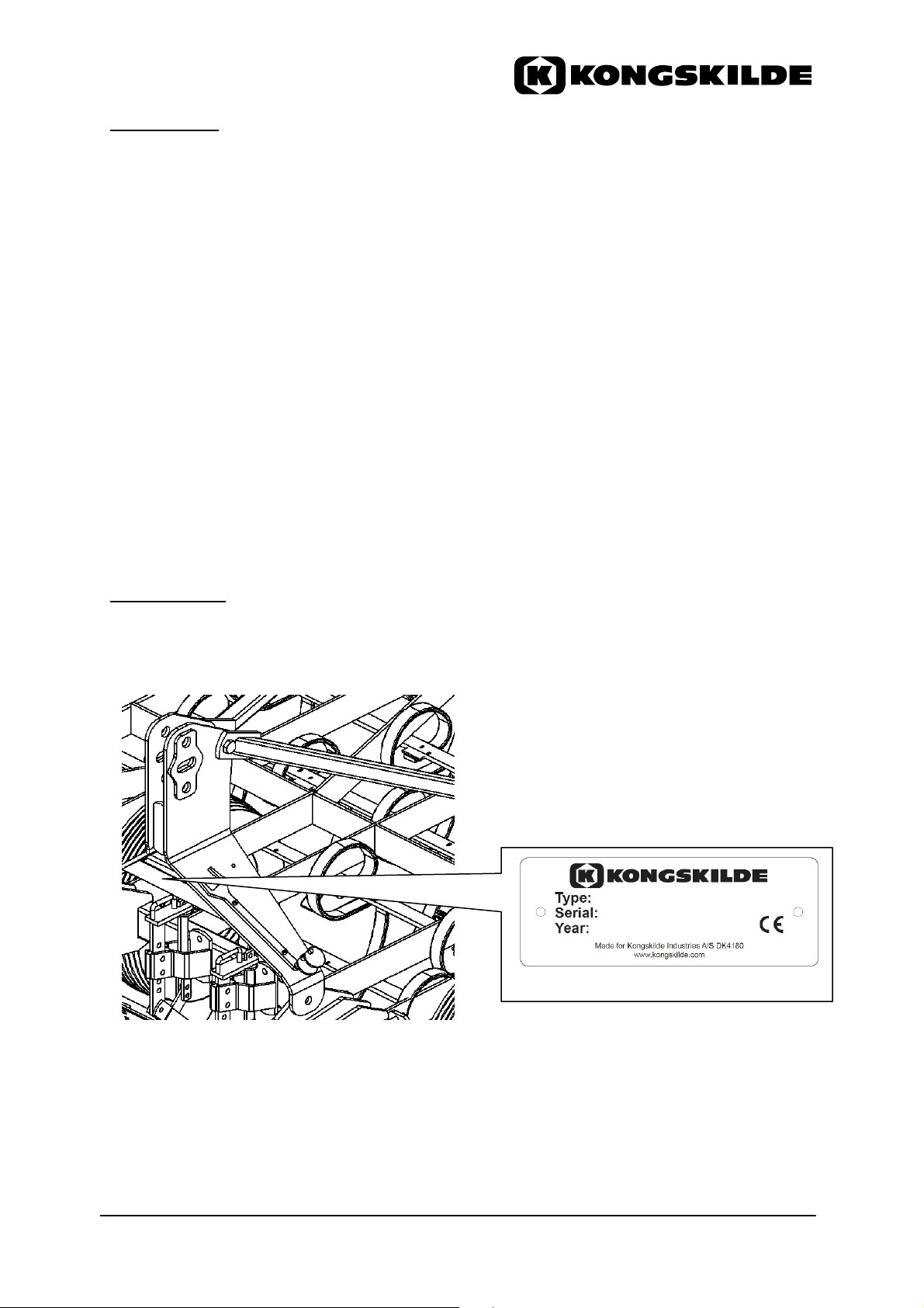
Identification ....................................................................................................... 3
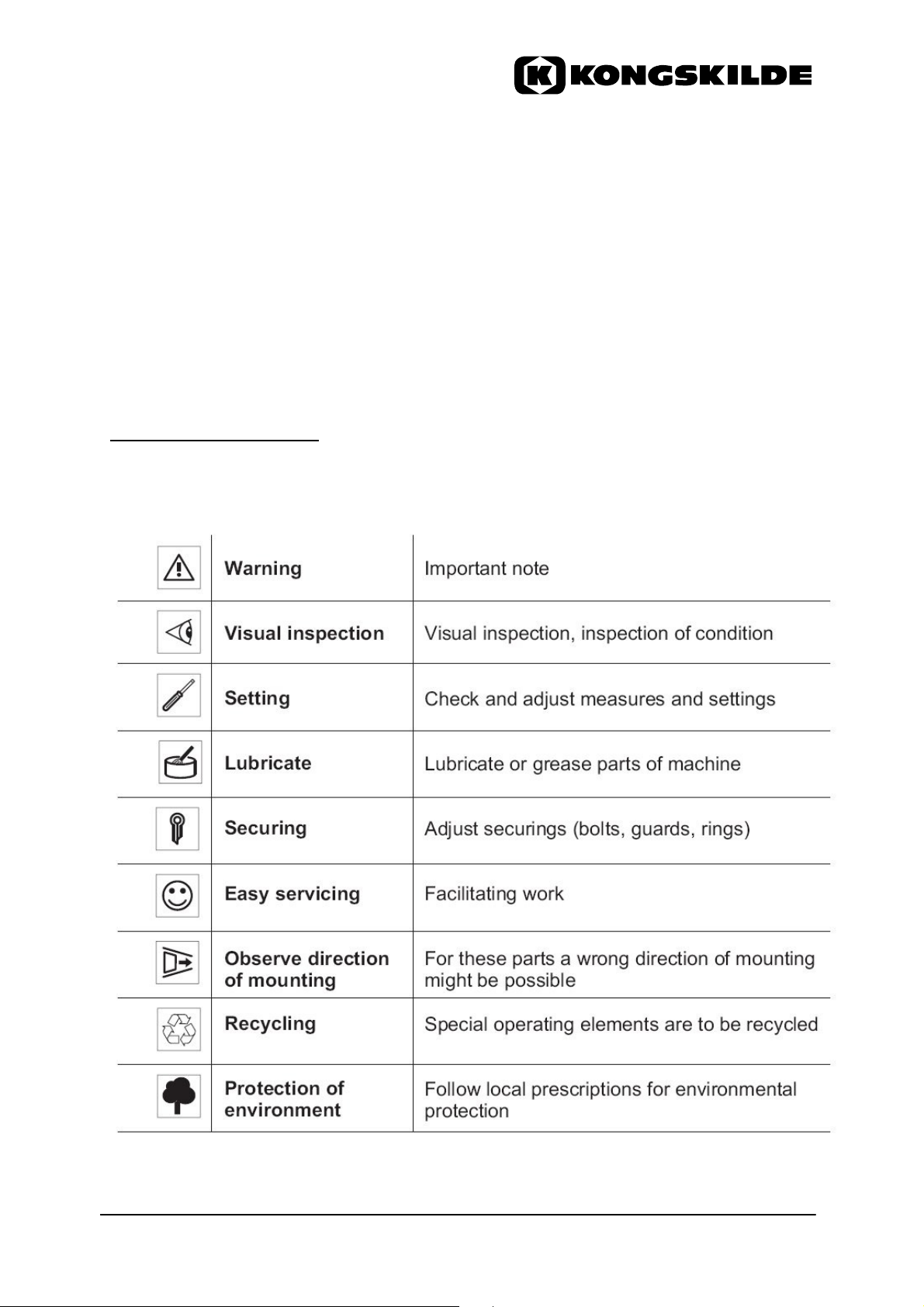
Explanation of symbols ..................................................................................... 4
Safety................................................................................................................... 5
General safety advice..................................................................................... 5
Coupling and uncoupling................................................................................ 5
Three point hitch or linkage ............................................................................ 6
Operation ....................................................................................................... 6
Transportation by road/transport .................................................................... 6
Before driving ................................................................................................. 7
During transportation...................................................................................... 7
After transportation......................................................................................... 7
Maintenance .................................................................................................. 8
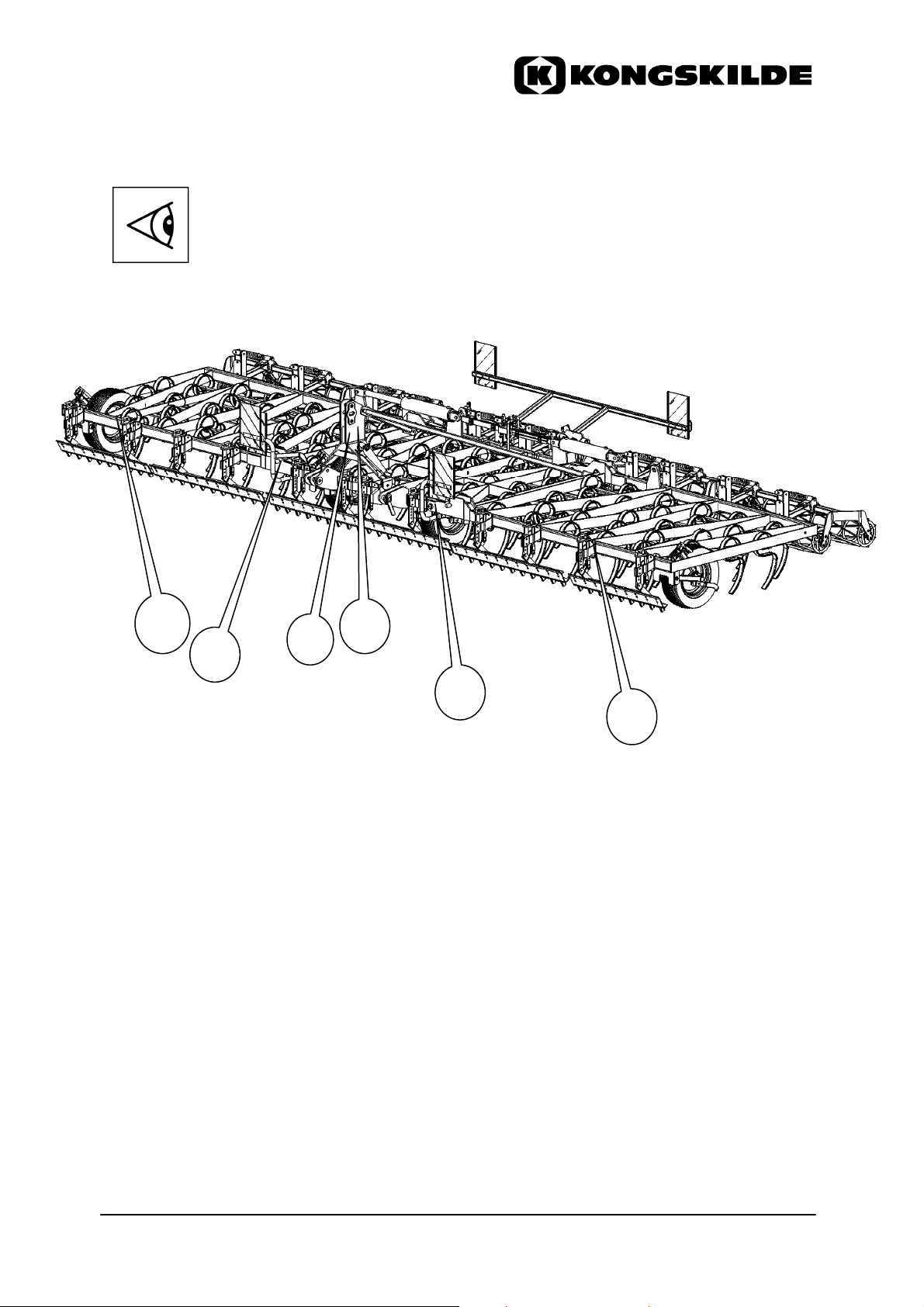
Safety decals.................................................................................................. 9
Technical data and dimensions ...................................................................... 11
Lifting points………………………………………………………………………… .12
Operation........................................................................................................... 13
Coupling ...................................................................................................... 13
Uncoupling ................................................................................................... 14
Adjustment of top link................................................................................... 14
Folding and unfolding with mechanical wing lock system...............................15
Folding and unfolding with automatic wing lock system..................................16
Preparing for road transport ........................................................................ 16
Adjustment and use of Vibro Master 3000 ..................................................... 17
Adjustment of the cultivator working depth .................................................. 17
Adjustment of the level board....................................................................... 18
Adjustment of the rear rollers (parallelogram) .............................................. 19
Adjustment of the long finger rear harrow .................................................... 20
Turning......................................................................................................... 21
Reversing ..................................................................................................... 21
Maintenance...................................................................................................... 22
General ........................................................................................................ 22
Tyre pressure ............................................................................................... 22
Lubrication.................................................................................................... 22
Warehousing and storage................................................................................ 23

3
Introduction
Congratulation with your new KONGSKILDE Vibro Master 3000!
The KONGSKILDE Vibro Master 3000 is a seedbed cultivator, based on the well
known vibrating KONGSKILDE tines.
Vibro Master 3000 is a fully mounted cultivator.
Vibro Master 3000 is mainly designed for the seedbed preparation before seeding.
Vibro Master 3000 can be equipped according to the specific demands with different
types of tines, levelling board and rear implements.
In order to obtain good weight distribution on the tractor, it is recommended always to
use adequate front weights on the tractor.
In order to get the full benefit from your new cultivator, Kongskilde Industries A/S
recommends to read this users manual, before taking the cultivator in use.
Kongskilde Industries A/S is convinced that you will benefit from your new Vibro
Master 3000!
Identification
The specifications of the Vibro Master 3000 can be found in the type plate. This is
located on the left side of the head stock, as shown on the below drawing.
Please note the specifications from the type plate:

4
Type: __________________________________ Name of implement.
No.: __________________________________ EDP identification number.
Serial: __________________________________ The serial number for the
specific implement.
For any queries regarding Vibro Master 3000 and for ordering spare parts, please
quote the above specifications.
The numbers for the spare parts can be found in the spare parts list supplied along
with this users manual.
Explanation of symbols
The symbols given in this manual will shorten the text and simplify working with the
document. Please study carefully all symbols and their meaning prior to operation.

5
Safety
General safety advice
−Before commissioning the Vibro Master 3000 read the operating instructions and
safety advice. It is mandatory to stick to the safety advice and the warnings stated
in the manual. The manufacturer declines any responsibility for accidents and
damages to the Vibro Master 3000 resulting from failure to apply safety advice.
−The Vibro Master 3000 should only be used, maintained and repaired by persons,
who are familiar with the safety advice and who are informed about the dangers.
−General safety advice and the regulations for the prevention of accidents must be
observed.
−The safety instructions must be passed on to other users.
−Use the implement only for soil preparation in farming.
Coupling and uncoupling
−Be careful when coupling or uncoupling implements to and from the tractor. Do
not stand between tractor and the Vibro Master 3000, when the tractor is moving.
−Fasten the implement only at the provided points.
−Check and attach transport equipment, for example lighting equipment, warnings
and possibly safety equipment.
−Observe the tractor's operating instructions.
−Use original and correct coupling parts.

6
Three-point hitch or linkage
−The attachment category for the three-point hitch on the tractor and the
implement has to match properly, or the appropriate adjustments must be made.
−Before coupling, check all linkage parts for cracks, missing components, loose
bolts and nuts etc. Make sure the implement will not disconnect by accident
during fieldwork or transport.
−While the implement, when mounted in the three-point hitch, is in transport
position, ensure sufficient locking at the side of the three-point linkage.
Operation
−Before each use, check the implement and the tractor as to their road and
operational safety.
−Before starting work, familiarise yourself with all facilities and operating elements.
It is too late to do so during work activities.
−Examine work surface for hidden obstacles, which could pose a risk (For example
under-ground cables, pipes).
−Adjustments should only be made on the implement, when it is completely parked
on the ground in unfolded position and when the engine of the tractor is switched
off. Remove ignition key and apply hand brake.
−Wear tightly fitting working clothes. Avoid loose clothes, which could be caught in
movable parts.
−Wear strong shoes or preferably safety shoes.
−Unauthorised persons are not allowed to stay in the working area during work. No
work is to be carried out, if there are unauthorised persons, especially children,
near the Vibro Master 3000 or in the danger zone of foldable parts without
keeping a safe distance.
−It is prohibited to allow any person to ride on the Vibro Master 3000.
−Never work diagonally to inclines or slopes, where there is a risk that the tractor
can tilt.
Transportation by road/transport
−When using public traffic routes, observe the regulations specific to the particular
country including the local maximum transportation width.
−The attachment of implements should not exceed the admissible total weight, the
admissible axle load and the weight-bearing capacity of the tractor tyres and the
capacity of the lift.
−The tractor must be suitable for the Vibro Master 3000.
−To ensure the ability to steer, the front axle load should always amount to at least
20% of the total weight of the tractor incl. cultivator.
−Hitch up the machine as far as it is necessary to ensure a safe road transport.

7
Attention!
The driving behaviour of the tractor changes.
Suit your driving according to the conditions of the street.
Pay special attention to the centre of gravity of hydraulic foldable machines.
Do not exceed a speed of 25 km/h when transporting Vibro Master 3000 on the road.
Before driving
−Observe admissible axle loads, total weights and transport measurements.
−For transportation on any public road, track or place, the legal transport width
according to local rules should not be exceeded. If the transport width is
exceeded, a special authorisation may be obtained under certain conditions from
the appropriate authorities.
−Road behaviour, performance, ability to steer and brake are influenced by
attached or coupled implements and ballast weights. Ensure that there is
sufficient ability to steer and brake.
−Before starting off the Vibro Master 3000, check the immediate area. Pay special
attention to children and that there is sufficient visibility.
−For road transportation with the implement raised, lock the control valves of the
tractor.
−Make sure that wing security locks are correctly locked.
NOTE:
The security locking devices prevents from accidental unfolding in case of a defect in
the hydraulic hoses. However, it may not prevent unintentional unfolding or lowering
if the control device is operated by mistake.
During transportation
−Riding on the implement during work and transport is not permitted.
−Never leave the driver's cab during transportation.
−When driving around corners and bends take the extra width and the inertia of the
Vibro Master 3000 as well as the high centre of gravity of the folded frame into
consideration.
After transportation
−Before leaving the tractor, set the implement down onto the ground, switch engine
off, remove ignition key and apply hand brake.
−No one should stand between tractor and implement without securing the vehicle
by the hand brake and/or stop chocks.
−Foldable frame parts should be completely unfolded. The implement must only be
parked with unfolded frame parts.

8
Maintenance
−Repairs, maintenance and cleaning work as well as the solving of functional faults
should principally only be carried out, while the engine is switched off. Remove
ignition key and apply hand brake.
−For maintenance on a raised up implement, always secure the Vibro Master 3000
on suitable stands.
−Do not ever go under the Vibro Master 3000 unless secured on suitable stands.
−Never attempt to disconnect hydraulic connections while system is pressurised.
−When changing work tools, which have cutting edges, use suitable tools and
gloves.
−Spare parts should correspond at least to the technical requirements defined by
the manufacturer. Use only original parts.

9
Safety decals
1
Inctructions
Read and observe the operating instructions.
Before commissioning the Vibro Master 3000,
read and observe both operating instructions
and safety advice.
Part no.: 71 000 187 250
2
Danger of crushing
Never reach into the danger zone, as long as
there could be moving parts.
Part no.: 71 000 629 549
3
Moving Parts
Do not stand near foldable frame of the Vibro
Master 3000.
Part no.: 71 000 629 546
4
Park in lowered position.
The Vibro Master 3000 must ONLY be
parked in working position.
Part no.: 71 000 646 708

10
Always keep safety decals in clean and readable condition!
Request substitutes for damaged or missing decals from the dealer
and place these at the intended positions!
3
2
4
1
2
3

11
Technical data and dimensions
Type
VM 30
65
VM 30
75
VM
3083
Working width 6,5 m 7,5 m 8,3 m
Transport width 3,0 m 3,0 m 3,0 m
Transport height *) 3.19 m 3.69 m 4.09 m
Hydr. folding YES YES YES
Weights, kg
Cultivator 1475 1725 1925
Level board 195 210 226
Double roller (C/R) 345 380 415
Hydraulic demands 1 double acting outlet required
Horsepower demand, HP 140 - 180 155 - 205 170 – 230
Maximum allowed HP 230 230 230
Number of tines, pcs
Vibro S
(10 cm tine space)
65 75 83
Vibro
Super
-
Q
(8 cm tine space)
81 93 103
Vibro Super
-
S
(10 cm tine space)
65 75 83
VTM
(15 cm tine space)
43 51 55
Dimensions, in mm
A 6500 7500 8300
B 1410 (1510 –
VTM tines)
1410 (1510 –
VTM tines)
1410 (1510 –
VTM tines)
C 3100 (3350 with
light kit)
3100 (3350 with
light kit)
3100 (3350 with
light kit)
D 2750 (2950 –
VTM tines)
2750 (2950 –
VTM tines)
2750 (2950 –
VTM tines)
E 2890 (2990 –
VTM tines)
3390 (3490 –
VTM tines)
3790 (3890 –
VTM tines)
*) with 30 cm ground clearance
A
E
D
B
C

12
Lifting points
When the Vibro Master should be lifted up or down from a truck by a crane or a
forklift the following lifting recommendations must be followed.
•Always use a crane or a forklift with the suffients strength and ballast to carry the
weight of the Vibro Master 3000.
•Always move the cultivator in unfolded position.
•Do not stay under the cultivator when lifting
Lifting the Vibro Master 3000 (with and without rear rollers connected) :
•Fasten one connection in the pin for the top link connection
•Fasten 2 connections to the rear connection points (side flat bars on main frame).

13
Operation
Coupling
Attention!
-While hitching up the Vibro Master 3000, stop the tractor and secure it from
rolling.
-Ensure that during coupling of the Vibro Master 3000, no one is standing between
the tractor and the implement. No one should stand in the operational range of
the implement.
The three-point linkage category of the Vibro Master 3000 and tractor must match
each other. Vibro Master 3000 can be connected by category 2 + 3.
If they do not correspond, the three-point linkage on the tractor must be adjusted.
Make sure that the Vibro Master 3000 is parked on solid ground and secure it against
rolling.
−Fit ball bushes in correct category over the pins for the lower links and the head
stock connections
−Lower the lower links of the tractor and drive backward until the lower link hooks
are under the ball bushes
−Raise the lift until the lower link hooks are hooked in.
−Put in the top link
−Secure all connections against unintentional opening
−Make sure the hydraulic fittings are clean and connect the hydraulic hoses.
−Connect light equipment (Optional)
−Control no oil is leaking from hydraulic connections
−Control all functions work correctly.
Cat. 3
– lower hole
for toplink and
outer latches for
lower linkages
Cat. 2
– inner
latches for lower
linkages
- Upper hole for
corrrect toplink
angle on large
tractors.
- Slotted / long hole
recommended for
unlevel field

14
Uncoupling
−Unfold the Vibro Master 3000
−Park the Vibro Master 3000 on levelled, solid ground.
−Remove the oil pressure from the connections
−Uncouple the hydraulic hoses from the tractor
−Disconnect the light equipment (Optional)
−Remove top link from the Vibro Master 3000
−Release the lower linkage hooks
−Lower the lower links until free of the ball bushes
−Drive tractor slowly forwards.
Adjustment of top link
The cultivator frame must stay horizontal during work to make both the front and the
rear row of tines work at the same depth. This is adjusted by means of the tractor's
top link. A short top link raises the rear row of tines whereas a lengthened top link
lowers the rear row of tines.
When using the toplink in the middle slotted/long hole (for uneven fields), the toplink
pin must have contact to the front side of the headstock, in order to prevent the back-
end of the cultivator dropping down.
When the cultivator works in the field the top link must be lower at the tractor end
than at the head stock of the cultivator.
The top link must never be horizontal or parallel with the lower linkages, as the
cultivator will run unsteadily and make steering of the tractor difficult.

15
Folding and unfolding (mechanical wing lock system)
When folding or unfolding make sure that no one are in the working range
of the implement
−Lift the implement off the ground, high enough to secure it does not hit during
folding or unfolding.
Unfolding:
−In order to ensure clearance between the hooks and the pins remember that the
wings should be folded in completely (4 degrees inside), before unfolding.
−Open the security hooks by pulling the 2 strings attached to the wing locks. If the
tractor hydraulic is slightly leaking, then there may be tension on the security
hooks. In this case operate the tractors hydraulic valve as to fold the implement
and then pull the strings.
−Use the hydraulics to unfold the Vibro Master 3000.
Folding:
−Make sure the strings for the security hooks are loose, so the security hooks are
in the lower position ready to lock the wings when folded up
−Use the hydraulics to fold the Vibro Master 3000.

16
−Make sure the security hooks have locked the frames in upright position
Folding and unfolding (automatic hydr. wing lock system)
Vibro Master 3000 can be equipped with an automatic wing lock system. Micro
cylinders are used instead of a string and work together with folding system for the
side wings.
Preparing for Road transport
−Make sure the string for the security hooks are loose, so the hooks are in the
lower position
−Lift the implement and fold as described
−Make sure the security hooks have locked the frames in upright position
−To give a lower point of gravity, and thereby a more stabile transport, it is
recommended to lower the implement to a lower level, but keeping sufficient
distance to road during transport.
−Secure that the implement is safe, that nothing will fall off, including big lumps of
soil, during transport.
−Check any light kits and warning plates that these are working and clean.

17
Adjustment and use of the Vibro Master 3000
The Vibro Master 3000 can be equipped with 4 different types of tines. See table
below for recommended settings and use.
Type of tine
Working depth
Working
speed
Tine distance
Conditions
Vibro S
(32x10,5 mm)
4 – 10 cm 8 – 12 km/h 10 cm Seedbed
Vibro Super Q
(32x12,4 mm)
4 – 10 cm 8 – 12 km/h 8 cm Seedbed
Vibro Super S
(45x11 mm)
4 – 12 cm 8 – 12 km/h 10 cm Seedbed
VTM*)
(50x10,8 mm)
4 – 12 cm 8 – 12 km/h 15 cm Seedbed with
some residues
*) As shares for VTM can be used 2 ½” goose foot (101000551) and 4“ sweep
(101000552) for shallow tillage.
Local conditions such as soil type, weather conditions, stones, amount of residues
etc. must always be taken into account when setting the cultivator.
Adjustment of the working depth (cultivator)
The cultivator must be lifted for adjusting the working depth.
The working depth is set by means of the wheel spindles on each of the 4 rubber
wheels. An indicator is showing the position of the spindle.
The depth wheels on the centre section must be set deeper than the depth wheels on
the wings, as they sometimes are running in the tracks from the tractor. As a general
rule can be used :
Depth wheels on the centre section must be set 1 scale-point deeper than the
wings.
After adjustment to the correct depth remember to position the handle in
the storage clip, to prevent the handles from turning during work.
Position for VTM tines
Position for S/SQ/SS - tines

18
Adjustment of the level board
Angle:
The level board has in general 2 different ways of
working:
•Crushing (upper hole) – the board is backward
angled and clods are crushed under the board
•Levelling – (lower hole) the board is more
vertical positioned and it has a better ability to
level out the soil surface.
To change from crushing to levelling mode:
•Remove the bolts
•Change the angle of the level board to match the
upper/lower hole
•Insert the bolts and tighten again
Height:
The bracket for the level board must be positioned according to the type of tine used:
The level board sections are hung up in 2 brackets. From here the height can be
adjusted.
•Pull out the ring clip of both pins
•Remove the pins
•Adjust to the wanted height
•Insert pins and ring clips again
Adjustment of spikes on the level board:
The spikes on the level board are possible to mount in 2 height positions. From the
factory the spikes are mounted in the upper hole. When the spikes get worn they
must be moved to the lower hole.
When worn out – replace with original Kongskilde spikes.
Crushing
Levelling
Height
adjustment
S/SQ/SS - tines VTM - tines

19
The level board is made for crushing and levelling – not for dozing big amounts
of soil!
Adjustment of the rear rollers
The rear rollers are attached to the cultivator by a arm, which follows the soil during
work and ensures optimal reconsolidation.
Attachment to the cultivator:
The rear harrow attachment must be connected to the cultivator. There are 2
possible connections, which depends on the type of tines used on the cultivator:
Adjustment of the pressure on the double rollers:
The pressure on the rollers can be adjusted
by using the tool for the spring adjustment.
There are 6 different positions. Adjustment is done by:
- Place the excentric tool (A) in the slot of the rod
- Turn the tool slightly until the pin (B) can be removed
- Adjust with the tool to the wanted pressure and insert the pin (B) again
- Repeat this for all arms
S/SQ/SS -
tines
Position 1 : New spikes (upper hole)
Position 2 : Worn spikes (lower hole)
VTM - tines

20
Minimum pressure on the rollers Maximum pressure on the rollers
Adjustment of the angle on the double rollers:
The attack angle of the rollers can be
adjusted. It is important to adjust this
according to the soil conditions. The front
roller must be set higher than the rear roller
(app. 10-20 mm), in order to prevent it from
digging too deep into the soil.
•Pull out the ring clip of both pins
•Lift front roller (use special tool)
•Remove the pins
•Insert pins and ring clips again
a
b
Table of contents
Other Kongskilde Tiller manuals