Kongskilde VIBRO TILL 2900 Series User manual

VIBRO TILL 2900
Field Cultivator - Assembly Guide
ASSEMBLY INSTRUCTIONS
Kongskilde
2900 Series
*Model may not be exactly as shown.
Kongskilde reserves the right to make changes to product designs and
specifications without notice or obligation to rework.
See your local Kongskilde representative for current product specifica-
tions, instructions and options.
660005033 - Revision 3

2
Index
Introduction: .......................................................................................................................3
Pre Assembly Instructions ..................................................................................................4
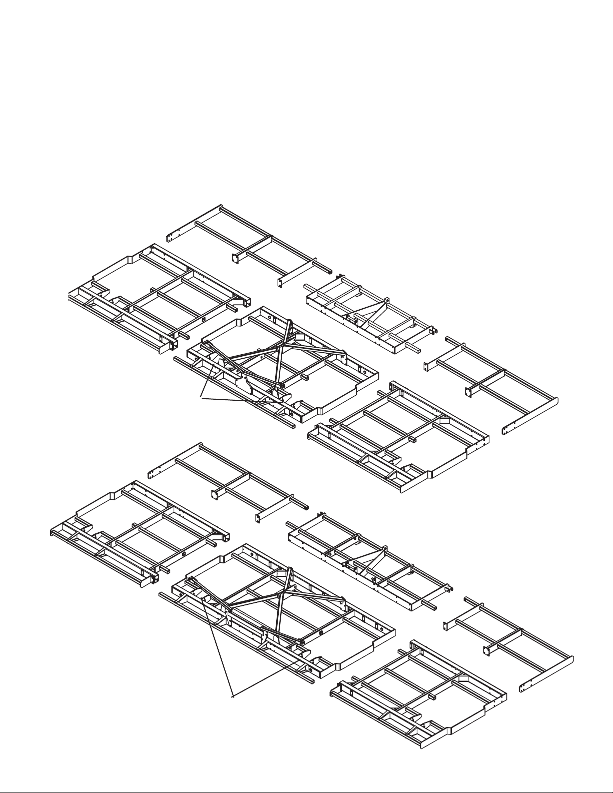
Frame Sections ...................................................................................................................5
Tine Locations: ..................................................................................................................6
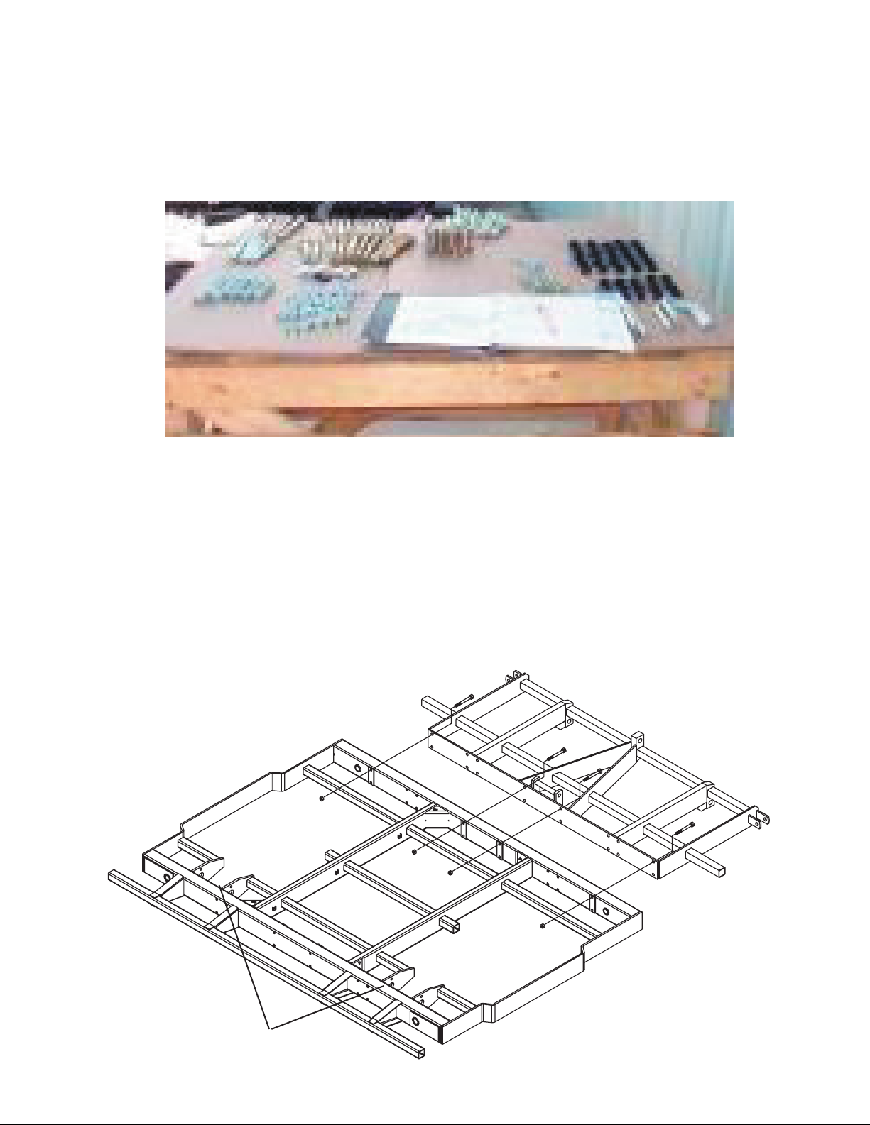
Hardware Organization: .....................................................................................................7
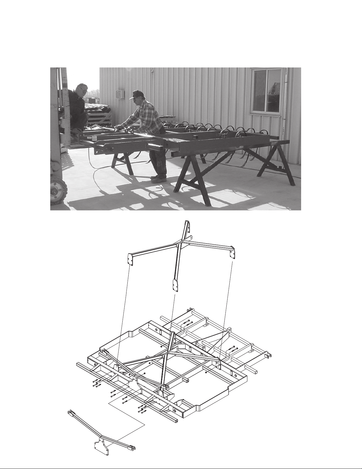
Frame Assembly: ...............................................................................................................8
Self Levelling (Narrow Center): ........................................................................................9
Self Levelling (Wide Center): ..........................................................................................10
Wheel Linkages and Tandems: ........................................................................................ 11
A-Frame Connection: .......................................................................................................13
Main Pivot Link: ..............................................................................................................15
Self Levelling Completion: ..............................................................................................19
Hitch Assembly: ...............................................................................................................21
Wing Assembly: ...............................................................................................................23
Fold Hinges: .....................................................................................................................24
Wheel and Hub Installation: ............................................................................................25
Wing Cylinder Pins: .........................................................................................................27
Wheel Linkage Adjustments: ...........................................................................................28
Mechanical Adjust Wheel (1.0M Wing): .........................................................................30
Gauge Wheel: ...................................................................................................................31
Connecting Frame Sections: ............................................................................................32
Folding Cylinders: ...........................................................................................................33
Hydraulic Assembly Info: ................................................................................................34
Final Inspection: ...............................................................................................................37
Saftey Decal Installation: .................................................................................................38
Notes: ...............................................................................................................................43

3
Introduction:
Please take the time to carefully read and review all instruction booklets provided with your new
Kongskilde product.
These instruction booklets have been developed to assist you in assembling, adjusting and maintaining
your new Kongskilde Product. To obtain optimal performance over the lifetime of the product read and
follow these instructions carefully.
A copy of the Spare Parts List has also been provided in order to identify the components and hardware
needed for each step of the assembly and to help you identify and obtain replacement parts in the
future.
When the assembly of the unit is completed, please refer to the Owners Manual before attempting to
adjust or use the product. The Owners Manual will provide you with further instructions on the proper
Field Settings, Adjustments and Maintenance Procedures for Safe Operation of the unit.
If optional equipment or attachments have been ordered for your unit, please refer to the instruction
booklets provided for proper installation and adjustment of these accessories.
Please take the time to fill out and return the Owners Registration and Warranty Form provided with
the Owners Manual in order to activate the warranty coverage.

4
Pre Assembly Instructions:
Assembly of Kongskilde products should only be undertaken by authorized Kongskilde Dealers or an
approved service provider who has the necessary tools, equipment and training for safe handling and
proper assembly of the unit.
Proper handling and assembly of the components is critical in order to validate the warranty policy.
It is important to note that the frame components are heavy and somewhat awkward to handle. Proper
lifting devices such as overhead cranes, boom lifts or mobile lift trucks should be used at all times when
moving or handling the large frame components and must only be operated by individuals who have had
the proper safety training for using such devices. Proper steel assembly stands or support jacks should
also be used to support the frame components and prevent them from falling during assembly.
Recommended assembly tools include:
A full set of standard open or box end wrenches and sockets; assorted sizes of pin punches; a heavy
hammer and/or sledge hammer; a pry bar; a large adjustable wrench; and pair of visegrip or similar
type pliers.
Optional tools could include an all purpose jack and a good quality air or electric drive impact tool
with heavy drive sockets.
The assembly area should be should be large enough to allow workers and equipment to move around
freely during assembly of the unit.
For example; to fully assemble a 2900-90 with 29' (9m) working width, a minimum area of
30' x 40' (10m x 12m) with 16' (5m) overhead clearance is required to assemble and fold the
machine.
If the unit is to be assembled and folded indoors, additional clearance may be needed in the assembly
area.
The ceiling height and the size of the building exit door must also be considered in order to safely fold
and move the cultivator outdoor after assembly.
The floor area should be relatively clean and level.
Proper lighting and ventilation should also be provided to allow the work to be carried out in a safe
and efficient manner.

5
Frame Sections
Sort out the frame sections for the size of cultivator you are assembling. Note that there are 2 different
centre frame configurations as shown below: 1) 10' (3m) narrow transport model or
2) 13' (4m) wide transport model.
The main wing frames are the same for both the 3m and 4m models however, some compnents are
different such as the assembly hardware and hydraulic hose kits. Refer to the spare parts list supplied
for a full description of all of the different parts for both models.
Frame assembly with
10' (3m) centre section.
Frame assembly with
13' (4m) centre section.
The Center Frame has a top and bottom, Be sure the reinforcement plates at the
top of the wheelarm connection are on the bottom of the frame
Reinforcement plates to bottom
***

6
Cultivator frame.
Steel support stands.
Tines mounted in the wheel area or near the hinge
points should be left loose until after the wheel
arm assemblies and wing fold hinge plates are
installed. This will allow the tine to move out of
the way during assembly of the wheels and hinge
components.
Tine Scheme
Use the tine patterns booklet for the model of
cultivator you ordered and begin measuring the
tine locations on each of the toolbar tubes.
Note that there are 2 standard tine patterns:
4" (100mm), and 6" (155mm). Tine quantities
delivered with the unit are based on the model
size of cultivator and the tine spacing chosen at
time of order. Therefore, if you decide to change
the tine spacing after delivery of the unit you may
need to order extra tines depending on the pattern
you choose. Other tine spacings are available on
request for various special applications.
To ensure the stability of the frames and safety of the workers during assembly, place the cultivator
frames on surdy steel shop stands. Do not use construction blocks, tiles or supports constructed of wood
or other materials that could crush under continuous load. Position the stands so they do not interfere
with the mounting of frame components and tines.
Hook a tape measure on the "0" side of the cultivator frame and put a
mark on the front side or top of the toolbar tubes at the dimensions shown
on the tine pattern drawings. Mount the tines so they are centred at the
location marked. The mark will be covered by the clamp and bolt.

7
When the tines are mounted to the main frame and front extension, move the 2 frame sections together
and assemble the centre section with the bolts, nuts, washers and pins shown in the parts list.
Take care to insert the front frame bolts from the front and insert the back frame bolts from the back
so that the locknuts are all facing inside the machine. This will keep the frame assembly looking neat
and tidy and make the assembly more efficient.
(Note: The assembly diagrams do not show tines installed for easier viewing. In special situations
where the machine must be partly assembled and shipped to another location, the tines may be mounted
after assembly. But generally you will find it easier to mount the tines as you assemble each frame
section.)
Example:
10' (3m) Centre & Front Frame Assemby
Hardware Organization
Carefully unpack and lay out all of the fasteners and hardware. (The empty shipping crate and cardboard
makes an excellent temporary work bench.) Assembling the cultivator is more efficient if you take a
few minutes to sort and organize the hardware by type and size instead of dumping the bag or box in a
pile on the floor. Place the assembly instructions and parts list on the table for quick reference to help
identify the parts for each step of the assembly.
Reinforcement plates to bottom

8
Frame Assembly
Frame assembly can be done while the frames are sitting on the assembly stands, or the stands may
be removed once the tines are mounted. Use a fork lift or overhead hoist to move the heavy frame
components into position for assembly.
Carefully lift the front
frame into position for
bolting to the centre
section and top frames.
Move the top frame into position for bolting to the
centre section after the front frame is attached.
Install the centre folding
bracket with the bolts and
locknuts.

9
Self Leveling on Narrow Center
Although the 10' (3M) and 13' (4M) centre sections and self levelling wheel lift linkages have some
different components, they both have the same basic function and use the same order of assembly as
shown by the numbers below and opposite.
Sort out the pieces for the centre section self levelling linkages and wheel arms according to the parts
list and the diagram below for 10' (3m) or opposite on page 10 for the 13' (4m).
Important Note: It is much easier to pre-assemble the right and left wheel arms according to the
instructions on page 11. The entire wheel assembly can then be lifted into the frame and secured with
the wheel axle. The remaining steps for installing the linkages are outlined in detail beginning on page
12.
10' (3m) Self Levelling Linkage Assembly
1
3

10
Self Leveling on Wide Center
After the wheel arm assemblies are installed, the self levelling linkages can be attached starting with the
wheel connection link at the back and work forward to the hitch. The numbers below show the proper
order of assembly. Refer to the detailed instructions beginning on page 11 for proper assembly of the
wheel arms and self levelling lift linkages.
13' (4m) Self Levelling Linkage Assembly
4

11
Tandam Wheel Instructions
Carefully insert the wheel axle pivot bushings into the ends of the wheel arm tubes. Tap the bushings
into the ends of the tubes with a block of wood or rubberized hammer.
Before mounting the tires, install the wheel spindle bolts as shown.
Take care to install the pins from the
inside as shown with the clip pins on
the outside of the wheel arm.
Never use a steel block or hammer directly
on the bushings as they are from a material
which can crack or burr easily.
The linkage length from centre to centre "Di-
mension A" should be set at:
A = 28" (71cm) for 20" clearance tines.
A = 28.5" (73cm) for 24" clearance tines.
Wheel Linkage Assembly
Assemble the wheel linkage as shown below with the pivot pins provided.
Note that the wheel pivot link shown below is a 2 piece adjustable linkage. This linkage can be length-
ened or shortened as necessary to provide proper under frame clearance for 20" or 24" tine options.
This adjustable wheel link also provides side to side levelling for the centre section.

12
Using a lift truck or overhead hoist equipped with an approved lifting chain or strap, lift the wheel
arm assemblies one at a time into the centre frame as shown below before installing the Self Levelling
Wheel Arm Pivot Linkages.
The wheel arm pivots must be aligned with the holes in the frame and then secured with the axle pin
as shown in the detail below.
The pin can be coated with a light machine oil or grease to ease assembly but otherwise needs no lu-
brication as the pivot bushings in the wheel arms are oil impregnated.
Install the axle pin with lock tab pointing
down and secure with the bolt and locknut.
Considerable force is required to install
the axle as the tolerance is very close.

13
A-Frame Wheel Links
10' (3m) Self levelling Pivot
Links
A-Frame Conection
For the 10' (3m) centre, attach the short Wheel Link Connector to the Wheel Arm Pivot Links and
A-Frame Wheel Links with the bolts provided. Remember to install the spacer bushings so the upper
pivot point will not bind when the bolts are tightened.

14
For the 13' (4m) centre, the assembly is the same only the Wheel Link Connector is longer. Attach
the Wheel Link Connector to the Wheel Arm Pivot Links and A-Frame Wheel Links with the pins
provided.
13' (4m) Self levelling Pivot
Links
A-Frame Wheel Links

15
Install Main Pivot Link and
Master Cylinder
Attach the master cylinder with the pins provided.
The rod clevis attaches to the lug on the main pivot
link.
The butt end of the cylinder attaches to the lug in the
centre of the top cross frame.
Remove the protective port plugs so the cylinder
can be moved in or out during the assembly of the
remaining self levelling linkages.
Main Pivot Link
Install the 10' (3m) main pivot link with the long pin provided. When the main link is in place install
the 4-1/2" x 8" master cylinder as shown in the detail below. Be sure to install the stop collar kit on the
cylinder rod. Do not install the other linkages until both the main pivot link and cylinder are in place.
(The pivot link may have been installed at the factory)

16
The 13' (4m) main pivot installs in much the same way as the 10' (3m) except that the 13' main pivot is
larger and requires a central pivot pin and additional mounting pins to be installed in the outside pivot
mounts. When the main link is in place install the 4-1/2" x 8" master cylinder as shown in the detail
below. Be sure to install the stop collar kit on the cylinder rod. Do not install the other linkages until
both the main pivot link and cylinder are in place.
Attach the master cylinder with the pins provided.
The rod clevis attaches to the lugs on the main pivot
link.
The butt end of the cylinder attaches to the lug in the
centre of the top cross frame.
Remove the protective port plugs.
Install Main Pivot Link and
Master Cylinder
Pins for 13' (4m)
Main Pivot Link

17
Install the A-frame wheel links on the 10' (3m) centre as shown below. The wheel links are identical
so it does not matter which way you turn them.
Attach the front of the wheel linkages to the main pivot using the 1-1/4" (32mm) pin provided. It may
be necessary to extend or retract the cylinder rod by hand in order to line up the holes and install the
linkage pins. Take care to insert the roll pin to lock the pin in place when finished.
Attach the rear of the wheel linkage to the upper hole of the wheel pivot
link with the welded pins and secure with the locknuts provided.

18
Attach the rear of the wheel linkage to the upper hole of the wheel pivot
link with the welded pins and secure with the locknuts provided.
The A-Frame wheel links are the same for both the 10' and 13' centres, and are installed the same way
as shown below. The only difference is that the links are spaced wider apart on the 13' centre due to
the wider frame and wheel spacing.
Attach the front of the wheel linkages to the main pivot using the 1-1/4" (32mm) pins provided. It may
be necessary to extend or retract the cylinder rod by hand in order to line up the holes and install the
linkage pins. Take care to insert the roll pin to lock the pin in place when finished.

19
To complete the assembly of the self levelling wheel link system, install the front pivot link to the lug
in the centre of the front frame. Attach the wide end of the large triangular self levelling link to the
main pivot with the long pin provided and attach the narrow end to the front pivot link with the shorter
pin provided. These parts are the same for both the 10' and 13' centres and are installed in the same
manner.
Check the assembly of the self levelling linkages and make sure all of the locking pins are installed
and locked.
Self levelling link
Front hitch
pivot link
Detail view of front linkages on
10' (3m) centre
Overview of completed 10' (3m)
self levelling linkage system.

20
The diagram below shows the completed 13' (4m) centre frame and self levelling wheel lift linkage
assembly.
Take care to go over the assembly of the centre section and linkage system to make sure that all nuts
and bolts are installed and tighened.
Check all pin connections and make sure the roll pins or clip pins are installed and locked.
If there is enough of room in the assembly area, the hitch can be assembled to the centre section now.
However if space is limited, the draw hitch can be assembled and attached later after the wings are
assembled and attached.
The hitch must be attached prior to installing the hydraulic lines and preparing the cultivator to be
raised and folded for transport.
This manual suits for next models
8
Table of contents
Other Kongskilde Tiller manuals