Tighten
Loosen
Loosen
Tighten
Dolly
Dolly xing lever
Tripod xing knob
Dolly caster lock
Lock
Tighten
Tripod support
Elevator
Ensure a
height to
insert an
screwdriver.
1
2
3
2
Tilt lock lever
Pan lock
knob
Swing angle adjusting lever
Loosen
Tighten
Swing
adjusting
plate
Fixing screws
Holder
clamp A
Tripod leg
(ø32 or ø30)
Holder
clamp B
AD adapter
holder
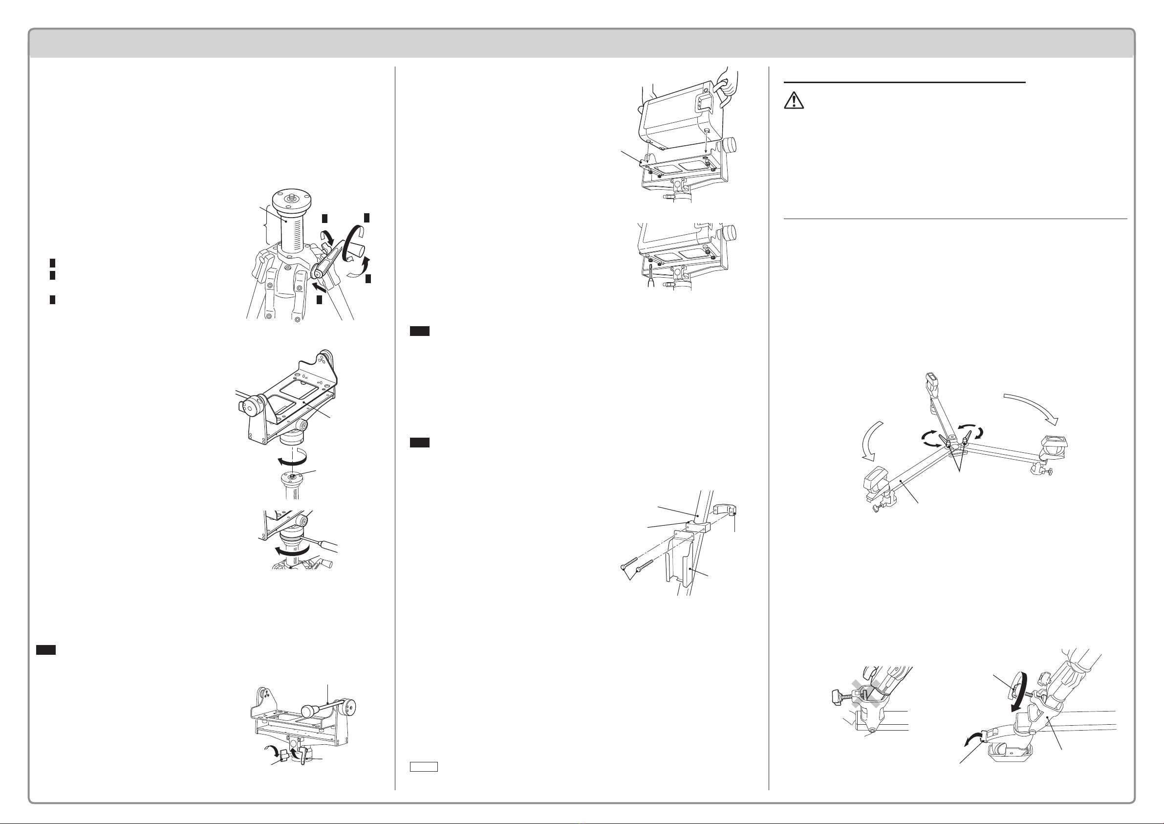
Assembly Procedure
1. Open the tripod.
(1) Open the tripod to an appropriate width, without extending the legs.
Fastenthetripodlegswiththetripodxingscrewsatthreepoints.
2. Raise the elevator.
Raise the elevator to a height
that provides enough space to
insert a at-blade screwdriver
under the platform when
mounting the tripod platform.
(Procedure)
1Loosentheelevatorxingscrew.
2Pushthelock,andraisethe
elevatorup/downlever.
3Turningtheelevatorup/downlever
clockwiselowerstheelevator.
Turningthelevercounterclockwise
raises the elevator.
3. Mount the tripod platform.
(1) While holding the tripod
platform with both hands, set
the tripod platform to the tripod
platform mounting screw at
right angles, and mount the
platform by turning it clockwise.
(2)
Insert the driver tip of the assembly
tool into the hole in the bottom of
the platform and then turn it
clockwise to tighten it further.
(3)
After completion of the above
procedure, adjust the tripod
platform height appropriately by
turning the elevator up/down lever.
4. Mount the RANGE7 to the tripod platform.
Note
Checkthatthetripodissecurelyopened,andthateachxingleverissecurely
tightened.
MounttheRANGE7onastableoor.
(1) Adjust the platform swing plate
mounted on the tripod set
horizontally, and x it.
* Make sure that the tilt lock
lever and the pan lock knob
are tightened.
(2) Holding the handles of the
RANGE7, place it on the swing
plate.
PlacetheRANGE7sothatthetwo
rubber legs on the backside of the
four legs on the bottom of the
RANGE7securelytthepositioning
holesontheswingplate.
(3)
Insert the four screws attached on
the rear side of the swing plate into
the platform mounting screw holes
on the bottom of the RANGE7. Turn
the screws clockwise and tighten
them securely.
Note
ReversetheaboveprocedurewhenremovingtheRANGE7.
Thexingscrewsonthebottomoftheswingplatearenormallydesignednotto
dropoff.Pleasenote,however,thattheymaydropoffifyouturnthemforcefully
awayfromthepositionallowablefortheremovaltheRENGE7.
5. Attach the AC adapter holder
Note
You need to extend or contract the tripod legs for operation. Please decide the
mounting position of the AC adapter holder on the tripod after taking into
accounthowtobesthandlethecord.
(1)
Align the AC adapter holder with
“the holder clamp A” and put
the two xing screws through.
(2) Place the AC adapter holder and
holder clamp A on the tripod
leg, and use holder clamp B to
support the screws. Tighten
them lightly.
*Tightenthetwoscrewsalternately
littlebylittle,insteadoftightening
only one of them at a time. They
mustbeequallytightened.
6.
Completion of assembly (Final check before measurement)
Re-checkthetripodandplatformmountingpartsforloosenessorshake.Ifany
partislooseorshakes,re-tightenitsecurely.
CheckiftheRANGE7willnotbecomeunstablewhenitistiltedforward.Ifthe
RANGE7maybecomeunstable,openthelegsmorewidely.
Memo
Fordetailsregardingwiring,pleaserefertotheRANGE7instructionmanual.
How to Use the Optional Dolly VI-B41
PRECAUTIONS FOR USE
Duringmeasurement,activatethedollycasterlocktopreventthetripodfrom
accidentally moving.
Donotstepon,ormountthedolly.Doingsomayresultinoverturn,injury,or
damagetotheequipment.
Tomovethetripodwhileusingthedolly,releasethedollycasterlock,andslide
thetripodslowly.Abruptmovementcausesthecasterstobecaughtinastepor
obstacle,resultinginoverturning.
Onathick-piledcarpet,etc.,thecastersmaynotmovewell.
1. Assemble the dolly.
(1) Set the dolly as shown on the right. Turn the two dolly xing levers on
the movable legs counterclockwise to loosen the levers appropriately.
Ifthedollyxingleverisexcessivelyloose,itcomesoffandfalls.
(2) Open the two movable legs equipped with the dolly xing
lever, and fasten the legs as shown on the gure.
Makesurethatthetwoopenedmovablelegshavebeensecurelytinthe
guidegrooves,andfasteneachlegbyturningthedollyxingleverclockwise.
Turnthedollyupsidedown,sothatthecastersareplacedontheoor.
2. Set the tripod on the dolly.
(1) Insert the three legs of the tripod into the individual tripod supports at
three places on the dolly, and fasten the legs.
Toconductthisstep,activatethedollycasterlock.
Loosenthetripodxingknobsothatthetripodlegscanbeinsertedintothe
tripodsupports(atthreeplaces).Then,insertthethreelegsofthetripodintothe
tripod supports.
Adjusteachtripodsupportsothatthetripodxingknobisperpendiculartothe
tripodleg.Then,fastenthelegwiththetripodxingknob.
 User manual")


