Konig & Meyer Suspensor 42080 User manual

DJ-Tisch »Suspensor« 42080
-42080.000.55-
-03.80.822.00- 1/03
1. Was der DJ-Tisch alles bietet
-Ideal für zwei Plattenspieler und einen Mixer. Falls Platz und Gewicht übrig ist, kann
noch zusätzliches DJ-Equipment getragen werden.
-Gefederte Auflageplatten schützen die Anlage vor Stößen und Vibrationen. Je 4 Feder-
elemente pro Platte sind vorinstalliert. Es können jeweils bis zu 6 weitere Federelemente
montiert weden. Voll aufgerüstet mit allen 20 Federn trägt jede der beiden Auflageplatten bis
zu 25 kg. Wer dem Tisch mehr Gewicht zumutet, bringt sich um seine besonderen Vorteile:
Die Auflageplatten können sich durchbiegen und vor allem wirkt die Federung nicht mehr.
-Großzügig dimensionierte Auflageplatten (zusammen 161 x 49 cm)
-Höhenverstellung (min. 77 cm / max. 115 cm)
-Sicherer Stand durch Bodenausgleichsschrauben
-Sehr gute Verarbeitung
-Ersatzteilversorgung
-Kompaktes Transportstück (60 x 16 x 85 cm; 24 kg)
2. Hinweise zur Betriebssicherheit
-Montage mit geeignetem Installationsmaterial
-Tragekraft max. 25 kg pro Auflageplatte
-Federung an Gewicht anpassen
-nur für DJ-Equipment
-Scharnier 5:
Achtung Quetschgefahr!
-Rasterung 9muss bei Betrieb eingerastet sein
-Füße müssen mit Klemmmutter 4am Rahmen verschraubt sein
-Bodenunebenheiten durch Bodenausgleichsschrauben 19 neutralisieren
-Zapfen 25 der Schrauben 21 müssen in das Fußrohr 20 hineinragen
max.
25 kg max.
25 kg
max.
25 kg
max.
25 kg
24 mm (max. Federweg)
169 cm
161 cm
181 cm
49 cm 60 cm
60 cm
85 cm
16 cm
max. 115 cm
min. 77 cm
Seite 1
-42080.000.55-
-03.80.822.00- 1/03
DJ-Tisch »Suspensor« 42080
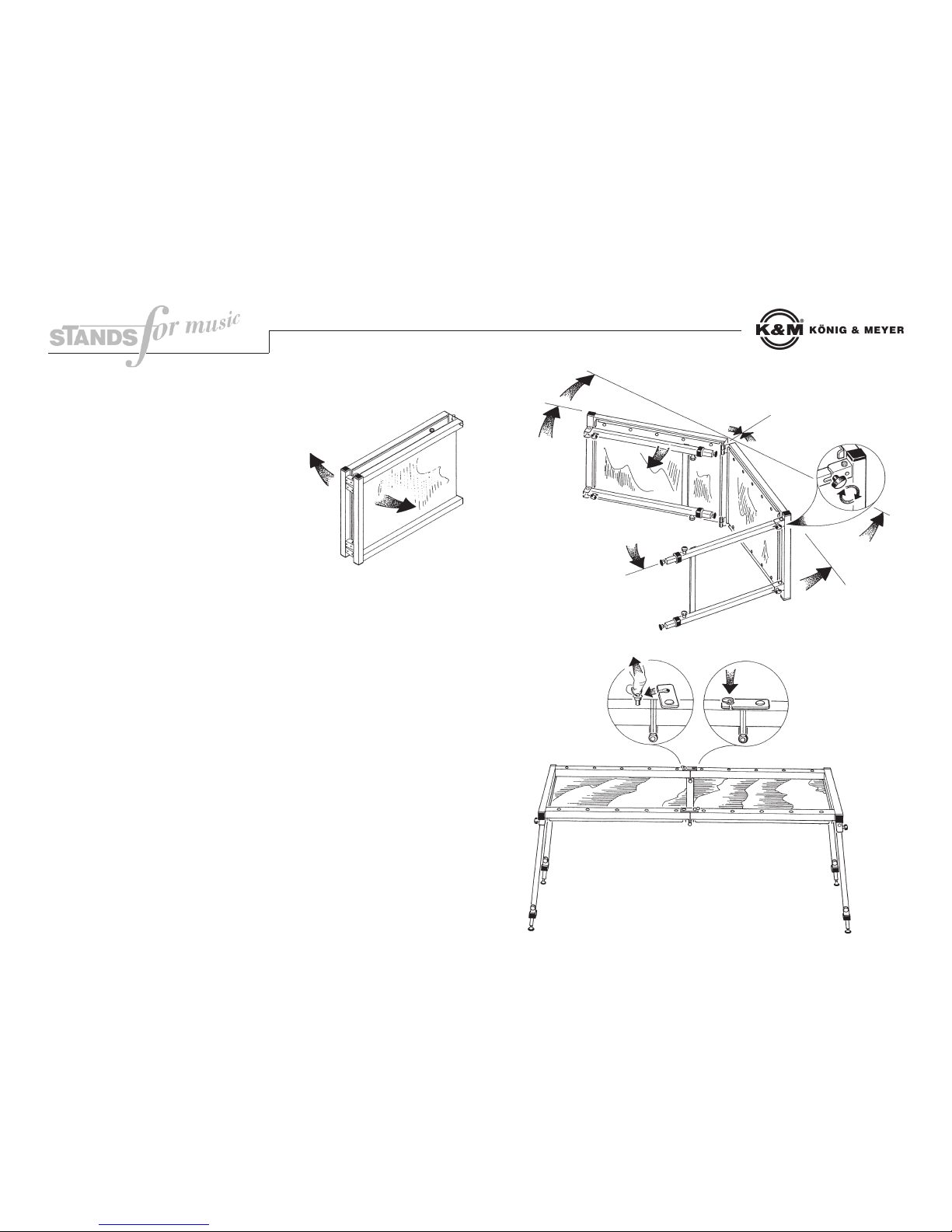
3. Aufstellanleitung
1Die beiden Tischhälften auseinander ziehen
2bis sich ein ca. 150 Grad Winkel bildet.
3Die Fußgestelle bis zum Anschlag herausklappen.
4Die vier Füße mit den Klemmmuttern an den
Anschlägen festschrauben.
5Die beiden Tischhälften nun vollständig aufklappen.
6Den Tisch auf die Füße stellen.
7Den Raststift am Ring nach oben ziehen.
8Den Riegel unter den Raststift schwenken.
9Raststift jetzt einrasten lassen.
(Schritte 7,8,9 an Vorder- und Rückseite des
Tisches durchführen).
Das Zusammenklappen des DJ-Tisches
erfolgt in umgekehrter Reihenfolge.
1
1
2
2
3
3
4
5
6
7
89
Bitte beachten: die angegebenen Positions-Nummern
entsprechen nicht den Ersatzteil-Bestell-Nummern!
Seite 2

-42080.000.55-
-03.80.822.00- 1/03
DJ-Tisch »Suspensor« 42080
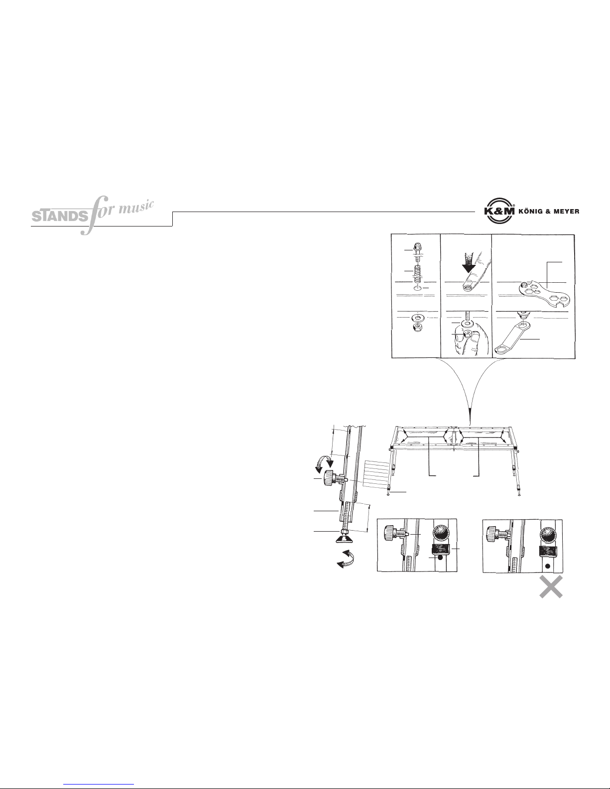
4. Das Einstellen des DJ-Tisches
Die Federkraft
Pro Auflageplatte sind vier von zehn möglichen Federelementen vormontiert 10. Das entspicht
einer Belastbarkeit von 10 kg.
Montage weiterer Federn:
- Feder 11 über Gewindestange 12 schieben. Beides von oben durch die Bohrungen 13 des
Tischrahmens und der Auflageplatte stecken.
- Stange 16 gegen Federdruck so weit wie möglich nach unten drücken.
- Mutter M6 14 und U-Scheibe ø12 15 von Hand auf Gewinde schrauben.
- Anschließend mit den beiden Schlüsseln 17, 18 verschrauben bis der obere Schlüssel über
dem Sechskantkopf durchrutscht.
Sind alle zehn Federelemente montiert, beträgt die Tragkraft einer Auflageplatte 25 kg.
Die Höhe
Die Füße 22 sind ausziehbar und können in acht Positionen 23 arretiert werden - bei einem
Abstand von jeweils 50 mm sind das zusammen 350 mm.
- Schrauben 21 lösen
- Fußrohr 20 verschieben
- Schraube 21 wieder einschrauben
Achtung: Der Zapfen 25 der Schraube muss in eine der acht Bohrungen am Fußrohr
hineinragen. Das ist für die Standsicherheit unbedingt erforderlich.
Tipp: Zapfen 25 kann in das Fußrohr eintauchen, wenn ein anderes Loch 24 sich genau
unterhalb der Kappe 26 befindet.
Die Standsicherheit
Bodenunebenheiten können durch Verdrehen der Ausgleichsschrauben 19 neutralisiert
werden.
Füße sollten so eingestellt sein, dass sich die Auflageplatten in waagerechter Stellung
befinden.
Zapfen der Schrauben müssen ins Fußrohr hineinragen.
11
14
15
12
13
17
10
19
20
21
22
25
24
26
23
18
16
vormontiert
50 mm
60 mm
Richtig Falsch
Bitte beachten: die angegebenen Positions-Nummern
entsprechen nicht den Ersatzteil-Bestell-Nummern!
Seite 3

DJ-Table »Suspensor« 42080
-42080.000.55-
-03.80.822.00- 2/04
1. What all the DJ-Table provides
-Ideal for two turntables and a mixer. If space and weight are still available, additional DJ-
equipment can also be supported.
-Spring-mounted supporting plates protect the system against impacts and vibrations. Four
spring elements each per plate are preinstalled. Up to six other spring elements can be
mounted. Fully equipped with all twenty springs, each of the two supporting plates bears up
to 25 kg. Those who overtax the table with more weight will rob themselves of its special
advantages: The supporting plates might sag and, most importantly, the suspension will no
longer function.
-Spaciously dimensioned supporting plates (together: 161 cm x 49 cm)
-Adjustable height (min. 77 cm / max. 115 cm)
-Secure stand provided by floor compensation screws
-Very good workmanship
-Spare parts supplied
-Compact transportation unit (60 x 16 x 85 cm; 24 kg)
2. Information on Safe Operation
-Assemble with suitable installation materials.
-Max. load capacity of 25 kg per supporting plate
-Adjust the suspension to the weight.
-Only for DJ-equipment
-Hinge 5: Caution: DANGER OF GETTING PINCHED!
-Snap-in lock 9has to be snapped in when in use
-The legs have to be bolted to the frame with the locking nuts 4.
-Even out any unevenness in the floor using the floor compensation
screws 19.
-The shaft ends 25 of screws 21 have to project into the leg tube 20.
max.
25 kg max.
25 kg
max.
25 kg
max.
25 kg
24 mm (max. travel of spring)
169 cm
161 cm
181 cm
49 cm 60 cm
60 cm
85 cm
16 cm
max. 115 cm
min. 77 cm
Page 1

-42080.000.55-
-03.80.822.00- 2/04
DJ-Table »Suspensor« 42080
3. How to Set up the Table
1 Pull the two halves of the table apart
2 until an angle of approx. 150 degrees is formed.
3 Fold out the leg stands as far as they will go.
4 Use the clamping nuts to tightly screw the four legs to the stops.
5 Then completely unfold the two halves of the table.
6 Set the table on its legs.
7 Pull the plunger pin on the ring upwards.
8 Turn the bolt under the plunger pin.
9 Then click the plunger pin into place.
(Carry out Steps 7, 8 & 9 on the front and
rear sides of the table)
Collapse the DJ-Table in the reverse order.
1
1
2
2
3
3
4
5
6
7
89
Note: The item numbers do not match the spare part
order numbers.
Page 2
-42080.000.55-
-03.80.822.00- 2/04
DJ-Table »Suspensor« 42080
4. Adjusting the DJ-Table
The spring resistance
There are four of ten possible spring elements pre-installed per supporting plate, this equals a
loading capacity of 10 kg.
Installing additional springs:
- Slide the spring 11 over threaded rod 12. Stick both from above through the holes 13 in the
table frame and the supporting plate.
- Press rod 16 as far as possible downwards against the force of the spring.
- Screw the M6 14 nut and the ø12 15 washer onto the threading by hand.
- Then screw down with the two wrenches 17 and 18 until the upper wrench slides over the
hexagon head.
When all ten spring elements have been installed, the load-bearing of one supporting plate is 25 kg.
The Height
The legs 22 are extendable and can be locked into eight positions 23. At a distance of 50 mm
each, this adds up to 350 mm.
- Loosen the screws 21
- Extend leg tube 20
- Retighten the screw 21
IMPORTANT: The shaft end of the screw 25 has to project into one of the eight holes drilled
in the leg tube. This is absolutely necessary for the stability.
Tip: The shaft end of the screw 25 can dip into the leg tube when another hole 24 is situated
beneath the cap 26.
The Stability
Any unevenness in the floor can be neutralized by twisting the compensation screws 19.
The legs should be adjusted such that the supporting plates are in a horizontal position.
The shaft ends of the screws have to project into the leg tube.
11
14
15
12
13
17
10
19
20
21
22
25
24
26
23
18
16
Pre-installed
50 mm
60 mm
Correct Incorrect
Note: The item numbers do not match the spare part
order numbers.
Page 3
Table of contents
Languages:
Other Konig & Meyer Dj Equipment manuals


