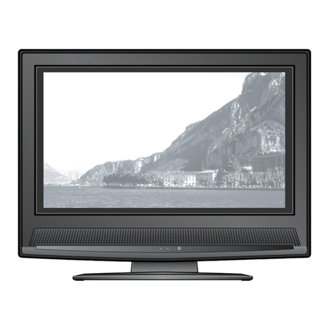
Konka KLC-TM1508 User manual

LCD TV SERVICE MANUAL
Model list
KLC-TM1508
KLC-TM2018
KONKA GROUP CO,LTD.
Digital Flat Display Division

IMPORTANT SERVICE SAFETY INFORMATION
Operating the receiver outside of its cabinet or with its back removed involves a shock hazard. Work on these
models should only be performed by those who are thoroughly familiar with precautions necessary when working on
high voltage equipment.
Exercise care when servicing this chassis with power applied. if carelessly contacted, can cause serious shock or
result in damage to the chassis. Maintain interconnecting ground lead connections between chassis, escutcheon, picture
tube dag and tuner when operating chassis.
When it is necessary to make measurements or tests with AC power applied to the receiver chassis, an Isolation
Transformer must be used as a safety precaution and to prevent possible damage to transistors. The Isolation
Transformer should be connected between the TV line cord plug and the AC power outlet.
It is important to maintain specified values of all components and anywhere else in the received that could cause
a rise in operating supply voltages. No changes should be made to the original design of the receiver.
Components shown in the shaded areas on the schematic diagram and/or identified by in the replacement parts
list should be replaced only with exact factory recommended replacement parts. The use of unauthorized substitute
parts man creates may create shock, fire, or other hazards.
Before returning the receiver to the user, perform the following safety checks:
1. Inspect all lead dress to make certain that leads are not pinched or that hardware is not lodged between the chassis
and other metal parts in the receiver.
2. Replace all protective devices such as non-metallic control knobs, insulating fish papers, cabinet backs, adjustment
and compartment covers of shields, isolation resistor-capacitor networks, mechanical insulators etc.
3. To be sure that not shock hazard exists, a check for the presence of leakage current should be made at each exposed
metal part having a return path to the chassis (antenna, cabinet metal, screw heads knobs and/or shafts, escutcheon,
etc.) in the following manner.
Plug the AC line cord directly into a 110V/220V/240V, AC receptacle. (Do not use an Isolation Transformer
during these checks.) All checks must be repeated with the AC line cord plug connection reversed. (If necessary, a
non-polarized adapter plug must be used only for the purpose of completing these checks.)
PLEASE READ BEFORE ATTEMPTING SERVICE
1. Use an Isolation Transformer when performing any service on this chassis.
2. Never disconnect any leads while receiver is in operation.
3. Disconnect all power before attempting any repairs.
4. Do not short any position of the circuit while the power is on.
5. For safety reasons, replace components any with identical replacement parts (SEE PARTS LIST).
6. Before alignment, warm up the TV for at least 30 minutes.
7. When removing a PCB or related component, after unfastening or changing a wire, be sure to put the
wire back in its original position.
8. Inferior silicon grease can damage IC's and transistors. When replacing IC's and transistors, use only
specified silicon grease. Remove all old silicon when applying new silicon.

9. Before removing the anode cap, discharge eletricity because it contains high voltage.
A. SPECIFICATION
System : Colour System:PAL,SECAM
Sound System:DK/BG/I/M
Audio output power 10%THD 1W X 2KLC-TM1508
10%THD 2W X 2KLC-TM2018
Antenna Impedance 75(Unbalance)
Power Consumption 48WKLC-TM1508
60WKLC-TM2018
Power Supply : AC~100-240V,50/60Hz (Adapter)-----KLC-TM1508
DC12V 4ATV------------------KLC-TM1508
AC~100-240V,50/60HzTV-------KLC-TM2018
item Port listKLC-TM1508
1RF cable
2 Video and Audio
3S-Video
4Headphone audio output
5VGA
5DC 12V input
item Port listKLC-TM2018
1 RF cable
2YPb /Cb Pr /Cr
3Audio2(YPb/CbPr/Cr and PC Audio
input)
4 VGA
6 Video and Audio1
7S-Video
8Headphone audio output
9AC Power input
1.Preface
1.1Applicable area

This test manual is applicable for KLC-TM1508.
1.2Test notes
1.2.1 Please follow the pointed test steps and choose the proper test equipment to
conduct adjustment, otherwise good effectof TVset could not be obtained. Pointed bias
voltage value should be ensured during test to get satisfied test result.
1.2.2 Be sure that you have the static electricity –protective glove in before test.
2 Test environment
1Temperature15~35°C
2Relative humidity 45 ~ 75%
3Air pressure: 86 ~ 106kPa
3 Test equipment
1) Computer 1
2) Oscilloscope100MHz1
3) Multimeter (VICTOR VC9801) 1
4) DC Voltmeter 1
5) Oscilloscope Tektronix2232 1
6) :PR-602A 1
7) : Tektronix TCP300 1A TCP312W 1
8) :Tektronix P6015A(1000 1)
1
9) "#$%Agilent34401A&' FLUKE 187/189 1
4The item and method of debugging
4.1Adjustment manual book of LCD panel Four-CCFL inverter
(PCB Board P/N:35007175)
4.1.1 Test method
4.1.1.1 While mesureing the inverter ,we usually connect the high voltage probe to the
output,but this will change the original path value called load effect. Most
high voltage probes have 3PF capacitacne such as Tektronix P6015A,when we
measure the Four-CCFL inverter,in order to balance the load effect of two
sides ,we advise using two high voltage probes to measure two side outputs.
OutL
CP
L
CCFL
L
3P Tektronix
P6015A
CS
CCFL
3P Tektronix
P6015A
CP
OutR
CS

4.1.1.2 For MP1018 project,the outputs have the capacitance divider ,see figure as
below,when we measure the output voltage,we may measure the parallel connection
voltage value of the C722 and C730 or C724 and C731,then according to theformula
Vout1=Vc1*(C722//C730)/C721,Vout2=Vc2*(C724//C731)/C723,we may get the output
voltage value(Vc1,Vc2 means the parallel connection voltage value of the C722
and C730 or C724 and C731). At the same time ,we should pay attention to the
followings :First,observe the output voltage waveform is distort or
not.Second ,observe the output waveform fr equency is between 40 kHz and 60kHz or
not.Third,disconnecting any output ,observe the start-up voltage and start-up
time is right or not.
4.1.1.3 Because the actual impedance and theoretical impedance of the LCD panel's lamps
have alittle tolerance,we pay more attention to the output current in actual
measurement.The LCD panel's lamps need aconstant current source to maintain
the brightness,so we may make ahigh frequency amperemeter in series with the

low-voltage output of XS702,XS703,XS704,XS705,then adjust the input voltage
equals 12V,as long as the current meets the requirement of the
specification(5.5--6.5mA),it can keep the brightness of the lamps.
4.1.1.4 Force 0-5V voltage to the input port that is the third pin of XS701.
Confirm if it will shut down at 0V and start at 5V.
4.2 Digital signal part
KLC-TM1508 start order
4.2.1 After turning on the power, if blank screen appears (no back light lamp), just
press POWER button several times, if blank screen still there,
4.2.1.1 Check if the voltage of every power supply is normal.
4.2.1.2 Check if the crystal oscillator Z402 (14.318180MHz), Z301 (24.576MHz)
oscillate or not, and oscillate frequency is right or not.
4.2.1.3 Back light control signal (BKLON) of PIN 3of XS514 has high level (about 5V)
or not, if not, chec kwhether fault sold ered or short circui thappened to
Q504,R580,R588.
4.2.2 If back light lamp lights but no screen displays,check N404 reset circuit
and crystal oscillator output to make sure CPU is under work, if CPU is
under work, then check signal channel. Signal channel is composed of two
parts: Video channel (including antenna, AV, S-terminal input) and RGB
channel for PC. If no picture displays or bad code displays when input
either of these two channel signal in turn, control signal maybe wrong,
then use oscilloscope to check waveforms at test points DEN, DVS, DHS
and DCLK are normal or not following the rule from back to front.
4.2.3 If just picture color has problem, then shift input to RGB input, and output
R,G,Bmono signal from computer to find the wrong color, then use oscilloscope
to test XS504 pin to find the wrong data cable following the same order.
4.2.4 If just video channel has problem, check N301 signal output VCLK,V-Hs,
V-Vs(TEST POINT), control signal -DVS DHS DCLK and DEN output from
movement compensation N404have waveform or not to find the problem.
4.3 IF Channel adjustment
4.3.1 Preparation steps
4.3.1.1 Connect (+) of RF of TV signal generator PM5518 to Pin 11 of RF TUNER
N1000, (-) to Pin 3of RF TUNER N1000.
4.3.1.2 Set TV signal generator PM5518 RF output to the maximum.
4.3.1.3 Set TV signal generator PM5518 RF Output to 38.0MHz, and set video
output signal of this signal generator to gray scale.
Turn on the
power 12V
N404 RESET and
IO port initialize Other IC electrify,
reset, initialize
Turn on LCD Panel
Supply Power
Turn on back light
lamp,Successful start

4.3.1.4 Connect DC Voltmeter “+” to Pin 8of N1000,- to RF TUNER cabinet.
4.3.1.5 Connect oscilloscope probe+ to Pin 10 of XP6010,- to RF TUNER
cabinet, then set oscilloscope to 50mV/div Time/div TV-H( s), and set
to TV-H simultaneously.
4.3.1.6 Connection between TV board and TESTER is shown as the following
figure (4).
4.3.2 Adjustment steps
4.3.2.1 Plug the power cord.
4.3.2.2 Turn T1000 magnetic core with ceramic aligner screwdriver so that
reading on DC Voltmeter is 2.5V 0.2V.
4.3.2.3 Waveform of T2 on the oscilloscope can be observed as the
figure (5) shown.
4.4 AGC adjustment
4.4.1 Preparation steps
4.4.1.1 Connect TV board whose IF has been adjusted to Power board and
motherboard (Do not install TV board into the back cabinet).
4.4.1.2 Set TV signal generator to 56 channel (855.25MHz), apply RF 62dB 3dB
half color bar signal and input to ANTENNA INPUT of RF TUNER.
4.4.1.3 Connect (+) end of DC Voltmeter to Pin 1of N1000 of RF TUNER, (-) end to
Pin 3of RF TUNER.
4.4.2 Adjust steps

4.2.2.1 Check if connections connect well, start automatic searching.
4.2.2.2 Press PROG./ button to display the channel you hav ereceived on the scre en
after automatic searching finishing.
4.2.2.3 Adjust VR1000with small screwdriver so that DC Voltmeter is within 2.0V –
2.5V(maximum),then reverse VR1000 and just make confusi onal of noi se
disappear on the picture.
4.5 White calibration adjustment
1Receiveblack or white signal under AV or PC mode, adjusting brightness and contrast to set
the brightness to 15Nit in dark area and 90 Nit in bright area.
2 Adjust white balance.Press(MENU”button once, then press “PRE.CH”five times to enter
factory menu, select “Temp”Menu,
Adjust Red 0-100
Green 0-100
Blue 0-100
3 Adjusting chromaticity coordinates of black and white to fit the requirement (X=0.313,
Y=0.329), or plug automatic calibration system to adjust white calibration automatically.
KLC-TM2018
1.Preface
1.1Applicable area
This test manual is applicable for KLC-TM2018.
1.2Test notes
1.2.1 Please follow the pointed test steps and choose the proper test equipment to
conduct adjustment, otherwise good effect of TV set could not be obtained. Pointed bias
voltage value should be ensured during test to get satisfied test result.
1.2.2 Be sure that you have the static electricity –protective glove in before test.
2 Test environment
1Temperature15~35°C
2Relative humidity 45 ~ 75%
3Air pressure: 86 ~ 106kPa

3 Test equipment
1) Computer 1
2) Oscilloscope100MHz1
3)Multimeter (VICTOR VC9801) 1
4)DC Voltmeter 1
5)Oscilloscope Tektronix2232 1
6)Cement Resistance 1
7)Test Clamp 1
8TV signal generator 1
4.T est item and met ho d
4.1Power SupplyBoard
4.1.1 The input and output characteristic test of power
4.1.2 Intention of test: Check input and output to find if short circuit.
4.2 checking method:
use Multimeter (VICTOR VC9801) of resistor to check
Number Item Test Point Standard
1The resistor of AC
input
AC Input Connector XS901 No short
circuit
2The resistor of V12
output
V12 output of connector XS902 No short
circuit
3The resistor of V12
assistant power output
Between the pins of C908 No short
circuit
Please check short circuit point on the PCB board if you find short circuit.
4.2.1 Test after supply AC 220V
4.2.2 Intention of test:
4.2.3 Supply AC 220V step by step,then the circuit start to work
4.2.4 Test the voltage of output
4.2.5 Short output test
4.2.6 The Peak-Peak value yawp test of the power output
4.2.7 The test of turning on and off TV
4.2.8 Checking method
4.2.9 Test the empty loading output of power supply Fix the power supply board on Test
clamp unconnecting theload then input 220VAC and turn on power switch to test the output
voltage by multimeter
Number Ietm Test point Empty loading Standard
1V12 voltage Output of V12 0.0A 12.0V 0.48
Listen if there is deviant noise at the same time.

4.2.10 Test the rated load output voltageTurn off the powerthen connecting the load
on output and turn on the power to test the output voltage by multimeter Rated load
output voltage /current are as follows:
Number Item Current standard Voltage standard
1V12 s rated load 5A 12.0V 0.48
Listen if there is deviant noise at the same time.
4.2.11 Test of V12 s shorting-output protect
Make the output shorted in 3seconds the output voltage should be 0V.after relieving
the short ,turn off the power and discharge the input filter capacitor C904 10 seconds
by discharge resistance (cement resistance 2-5W510 ),then supply the power again
using multimeter to test the output of power The output voltage should come back
normally 12.0V 0.48
4.2.12 The test of powers peak-peak value yawp output Under the rated load
Initialize the oscill oscope 50mV per unit and parallel-connect 0.1UF and 10UF capaci tor
on probe to see the output ripple is OK or not.
Number Item Test point Standard
112V output V12 output 150mV
4.2.13 The fully loading and empty loading experiment of turning on/off TV
Turn on/off TV per 5times every 5seconds under the two states .Make sure if the ou tput
is OK or not.
4.2.14 The standard of power aging experiment
Every product should aging 8hours under rated load and 45C Make sure the output
voltage is in regular range.
4.3 Digital signal part
4.3.1 Digital signal board power part

4.3.2 Verify the state of TV set
Please switch the TV on by “Power on/off” switch,then verify the LED color of touch
button.If it is red(standby state),the back-end power has been shut off(the voltage
of N802 No.5 pin is 0V),the supply power for IC-chip has been shut off except N803
normally working.Please test the voltage of D616 is 5V to verif ythe power of N803 no rmal
on standby state.
4.3.3 Checking Supply Power.
If the color of LED is green,the power supply for signal board(Test the Number
5,6,7,8 pin of N802 voltage is 12V).N801 supply 5V power(Test the anode of C853).N 810
N811 supply 3.3V(Tes tthe No.2 pin),N812N813 supply 1.8V(T est the No.2 pin)for main
IC N407,N305.
4.3.4 Digital signal part KLC-TM2018 start order
4.3.5 After turning on the power, if blank screen appears (no back light lamp), just
press POWER button several times, if blank screen still there
Turn on the
power
N407 RESET and
IO port initialize Other IC electrify,
reset, initialize
Turn on back
light lamp
Successful start
and LOGO display

4.3.6 Check if the voltage of every power supply is normal.
4.3.7 Check if the cr ystal oscillator Z4. 1(14.318MHz)oscillate or not, and oscilla te
frequency is right or not.
4.3.8 Back light control signal (BKLON) of PIN 3of XS512 has high level (above 3.5V)
or not, if not, check whether fault solder ed or short circuit happened to V507, R559 ,
R560,R561
4.3.9 If back light lamp is on while there is no display,check N407’s reset circuit
and the output of the oscillator to confirm the CPU is working or not.If CPU is
working ,then checking the signal channel. Signal channel has been divided into two
parts, general video channel(including antenna, AV, S-terminal input, Y, Cb, Cr) and
HDTV channel (Includi ng YPb Pr and RGB). Ifno any picture disp lays or bad code disp lays
when switching between these two channels, control signal may be wrong. Please use
oscilloscope to check test point DEN, DVS, DHS and DCLK from end to front to find
whether waveform displayed on the oscilloscope or not, if not, check if fault solder
or short circuit happ ened.If just picture color has problem, sw itch INPUT to RGB inp ut,
then input R, G, Bmon ochrome signal separately from computer to find the problem col ors.
Check data line of XS504 with oscilloscope according to the above form to find it’s
problem.
DCLK Waveform

DENWaveform
DHS Waveform

DVS Waveform
4.3.10 If only one channel has problem check the signal of this channel normal or
not.AV1,AV2,S-Video,Y,Cb,Cr are inputted from analog signal board to digital signal
board RGB Y Pb Pr(digital signal board)are input N407 by N603.Using oscilloscope
to check ICN1003’s output signal TV-Y,TV-Cb,TV-Cr,TV-HS,TV-VS(1 3 5 7 8pin of
XP1005),to verify the waveform is right or not.If not ,check whether fault soldered
or short circuit are happened Else ,check the 5V supply voltage of N601,N603 on digital
signal boardAs the Above orderwe may find the problem of RGBYPbPr video signal
Output acolor bar signal to AV1 by signal generator PM5518,check the waveform
if normal or not with oscilloscope.

CVBS color bar Wave form
TV_Y WaveformXP 10 05 ’s1Pin

TV_ Cb WaveformXP1005’s3Pin
TV_ Cr WaveformXP10 05 ’s5 Pin

TV _H sWaveformXP10 05 ’s7Pin
TV_V sWavrformXP1005’s6Pin
4.4 Analog signal board
4.4.1 Analog signal board power part
Analog signal board is supplied by 12V transformed to 5V by N1101,N1815After

connecting the power ,check the voltage of N1101’s 2pin with multimeter to seeif
the voltage of C1809 ‘s anode is right(about 5V) or not This is the back-end IC’s
normal power supply.
4.4.2 IF channel AFC adjustment on analog signal board
Input a38MHz IF Signal generated from TV signal generator to
RF TUNER according IF cable whose one side to 11 pin of RF TUNER and the other to 3pin
of RF TUNER(GND). IF channel AFC of LC-TM2018 has been adjusted automatically by software
which may check the power supply of IF IC is normal or notSee if the anode voltage
of C2224 is 5V or no tand check N1006 s 21 pin voltage is 2.50.2VIf not check
whether fault soldered or short circuit happened to R2029,R2030.
4.4.3 AGC adjustment on analog signal board
4.4.4 Preparation steps
4.4.5 Connect TV board whose IF has been adjusted to Power board and motherboard .
4.4.6 Set TV signal generator to 56 channel (855.25MHz), apply RF 62dB 3Db half color
bar signal and input it to ANTENNA INPUT of RF TUNER.
4.4.7 Adjust steps

4.4.8 Check if connections connect well, start automatic searching.
4.4.9 Press PROG.-/.button to display the channel you have received on the screen
after automatic searching finishing.
4.4.10 Press factory menu button to display factory menu on TV and select
TB1274 ,press PROG +/- button to select the tda9885 AGC item of sub-menu ,then
press volume +/- but ton to adjust the val ue until the snows ar edisappear The value
after adjusting is about 12-16 and the tuner voltage of first pin is about 2.0
0.2V.
4.5 White calibration adjustment
4.5.1 Receive black or white signal under AV or PC mode, adjusting brightness and contrast to set the
brightness to 5 Nit in dark area and 90 Nit in bright area.
4.5.2 Adjust white balance. Enter factory menu, select cal. Menu, and swap color temp item to user.
Adjust Red 0-255
Green 0-255
Blue 0-255
4.5.3 Adjust black balance. Enter factory menu, and select TB1274 Menu.
Adjust Red offset 0-127
Blue offset 0-127
4.5.4 Adjusting chromaticity coordinates of black and white to fit the requirement (X=0.304, Y=0.325),
or plug automatic calibration system to adjust white calibration automatically.

Trouble Shooting
Key IC listKLC-TM1508
Item Type Maker Package Circuit No. Qty.
1 PQ05RD11 Sharp N1001 1
2TDA1517P PHILIPS HDIP18 N2001 1
24LC16B/SN MICROCHIP3
AT24C16AN-10SI-2.7 ATMEL
SOIC-8 N309 1
4 74LVC541APW PHILIPS TSSOP-20 N514 1
5 74LVC32A D PHILIPS SO-14 N608 1
AM29LV800DT-70EC-AMD/# AMD6
MX26LV800BTC-55-3/# MXIC
TSOP-48 N307 1
71117-1.8V 1117 serial SOT223 N810*N811 2
81117-3.3V 1117 serial SOT223 N812*N817 2
MP1410ES-LF-SOIC-8-MPS MPS SOIC-8 N815 1
9SAA7114H PHILIPS LQFP100 N301 1
10 PW130-10Q PIXELWOR
KS 208PQFP N404 1
TDA9808T PHILIPS SO20 N1010 1
MSP3463G MICRONAS PMQFP64 N2000 1
11 BA033FP-ROHM ROHM N818 1
M385 LVDS MRT TSSOP-56 N502 1
12 MP1018EM MPS TSSOP28 N701 1
14 Tuner-AFT1/6000 Qingjia N1000 1
Key IC listKLC-TM2018
Item Type Maker Package Circuit No. Qty.
1 PQ05RD11 Sharp N1101 1
2TDA1517 PHILIPS SIL9MPF N2001 1
24LC16B/SN MICROCHIP3
AT24C16AN-10SI-2.7 ATMEL
SOIC-8 N306 1
4 74LVC541APW PHILIPS TSSOP-20 N508 1
This manual suits for next models
1
Table of contents
Other Konka LCD TV manuals

Konka
Konka DLC-3211UT User manual

Konka
Konka KLC-2718UG User manual

Konka
Konka KL26AS21Q User manual

Konka
Konka KL42CS62Q User manual

Konka
Konka L32K6RW MST6E16 User manual

Konka
Konka KDL32AT23U User manual

Konka
Konka KDL42MS19U User manual

Konka
Konka KL26CS66 User manual

Konka
Konka KLC-1508US User manual

Konka
Konka DLC-3211UT User manual