Konka KL32IS10 User manual

Please read this manual carefully before TV operation.
Retain it for future reference.
Record model number and serial number of the set.
See the label attached on the back cover and quote this information
to your dealer when you require service.


In case of smoke, strange noise or strange smell
from the unit:
Turn off the power switch immediately;
Disconnect the power plug from the power
outlet;
Contact your dealer or service centre. Never
attempt to make repairs yourself because this
could be dangerous.
·
·
·
High Voltage
Do not open
Risk of electronic shock, do not open.
Do not attempt to service this product yourself
as opening or removing covers may expose
you to dangerous voltage or other hazards.
Refer all servicing to qualified service personnel.
CAUTION
Important Safety Instructions
Important Safety Instructions and Maintenance
Never push objects of any kind into the set
through the cabinet slots as they may touch
dangerous voltage points or short-circuit parts that
could result in a fire or electric shock. Never spill
liquid of any kind on the set. Use special caution
in households where children are present. The
apparatus is not suitable for children under 3-year
to operate.
Power supply cords should be routed safety to
prevent life and property from dangerous with
damaged cord.
Mains plug is used as the disconnect device. It
shall remain readily operable and should not be
obstructed during intended use. To be completely
disconnected the apparatus from supply mains, the
mains plug of the apparatus shall be disconnected.
To reduce the risk of fire or electric shock, do not
expose this product to rain or moisture.
The apparatus shall not be exposed to dripping
or splashing and no objects filled with liquids,
such as vases, shall be placed on the apparatus.
To avoid the fire, no naked flame source,
such as lighted candles, should be
placed on the apparatus.
1

2
Important Safety Instructions and Maintenance
Important Safety Instructions
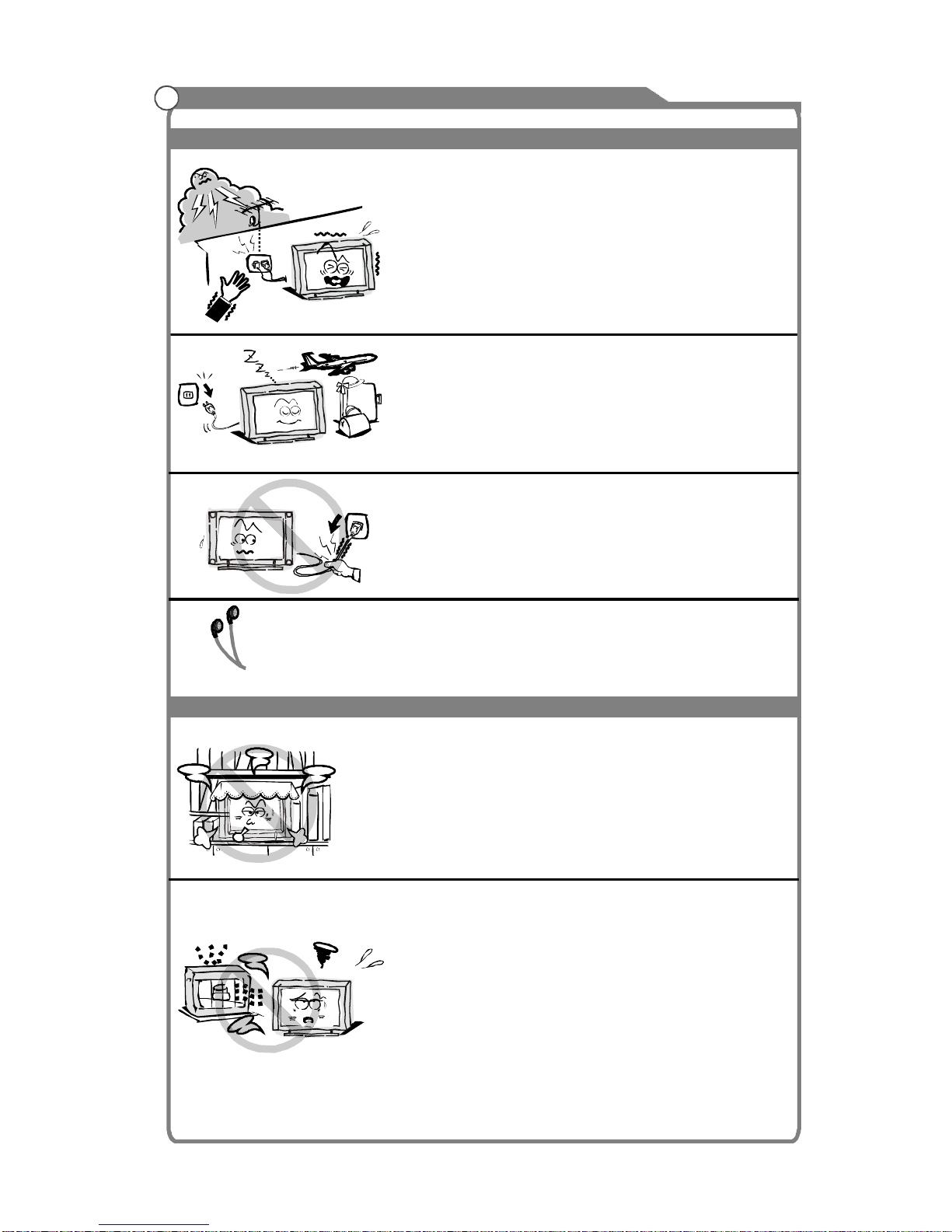
Always turn the set off when it is not being used.
Unplug the apparatus from the AC outlet when it will
not be used for a long period of time. And when there
is a lightning, unplug the unit from theAC outlet
immediately. Never touch the antenna wire during
lightning.
An outside antenna system should not be located in
the vicinity of overhead power lines or other electric
light or power circuits, or where it can fall into such
power lines or circuits. When installing an outside
antenna system, extreme care shold be taken to keep
from touching such power lines or circuits as contact
with them might be fatal.
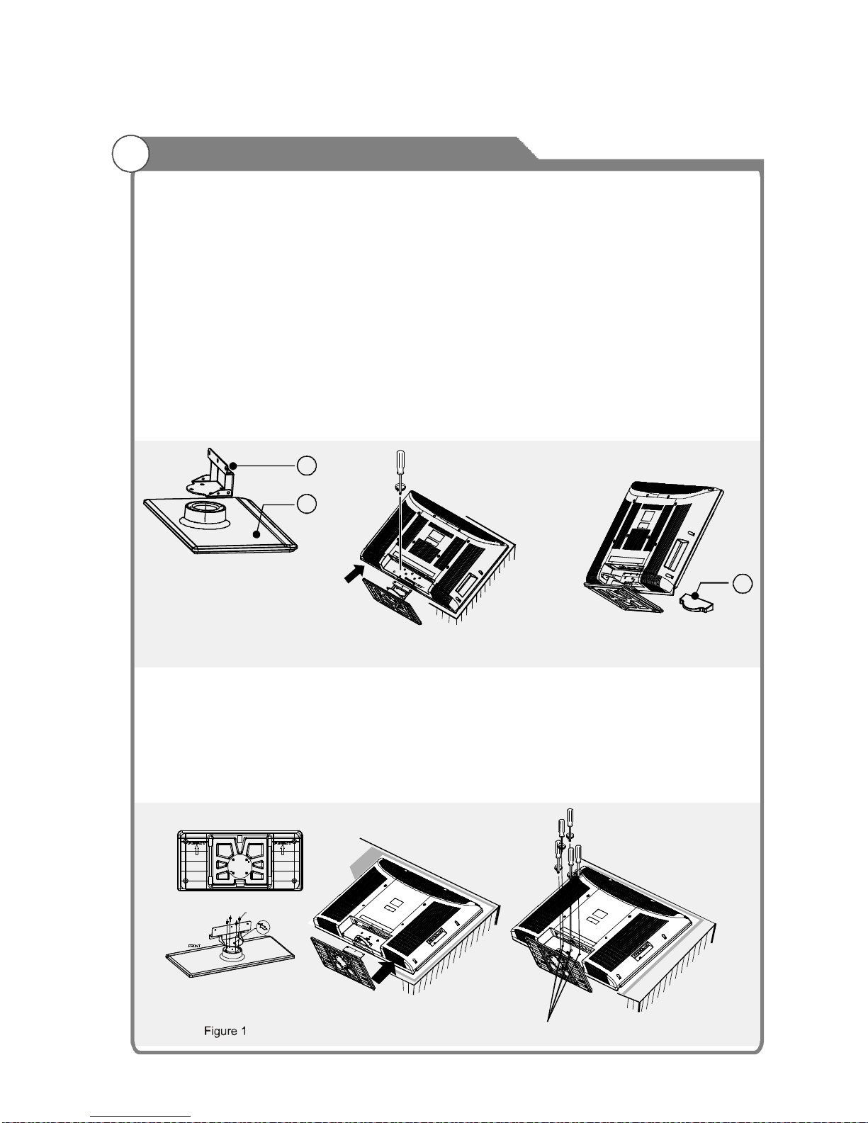
Installation
The ventilation should not be impeded by covering the
ventilation opening with items, such as newspapers,
tablecloths, curtains, etc.
At least 10 cm space should be left around the
apparatus for sufficient ventilation.
The product should be situated away from heat
sources such as radiators,heat registers, stoves, or
other products (including amplifiers) that produce heat.
Place the apparatus in such a position that the screen
is not exposed to direct sunlight. It is best to have soft
indirect lighting while watching and avoid complete
dark environment and reflection from the screen as
these may cause eye fatigue.
Keep the product away from high magnetic field (i.e.
power-amplified power speaker) to avoid affecting the
tint;
Do not pull the plug out by the wire;
Never touch the plug with wet hands.
Excessive sound pressure from earphones and
headphones can cause hearing loss.

3
Important Safety Instructions and Maintenance
Installation
Do not place this apparatus near water, for example,
near a bath tub, wash bowl, kitchen sink, or laundry
tub; in a wet basement; or a swimming pool; and
the like;
Cleaning
When the TV being moved in from cold place, it needs
some right time for dew inside unit evaporating fully
before turn on the unit;
Unplug this apparatus from the AC outlet before
cleaning. Do not use liquid cleaners or aerosol
cleaners. Use a damp cloth for cleaning;
Do not place the set on an unstable cart, stand, table
or shelf. The set may fall, causing serious personal
injury as well as damage to the product. Use only with
the cart, stand, tripod, bracket, or table specified by
the manufacturer, or sold with the apparatus. An
appliance and cart combination should be moved with
care. Quick stops, excessive force, and uneven
surfaces may cause the appliance and cart
combination to overturn.
To prevent injury, this apparatus must be securely
attached to the floor/wall in accordance with the
installation instructions.
Move

Welcome you to high quality image world KONKA colour LCD TV brings you. We sincerely
hope KONKATV brings you the brand new visual and audio enjoyment.
This operating instructions can help you operate this TV set easily.
Read this manual before operating the unit for being familiar with its features and keep it for
future reference.
Accessories
Introduction
General Description
External Connection
Supporting signals
Basic operation
Menu system instruction
Features
Specifications
Overview of front and side panel
Overview of back panel
Overview of remote control
Teletext Model
Installing Batteries in the Remote Control
Antenna connection
Input Setup
Channels Selection
Volume Adjustment and Mute Setup
Picture
Sound
Function
Stand and wall-mounted(optional)
Connecting VCR
Connecting S-VHS VCR
Connecting DVD Player/Set-Top Box via Component
Connecting a Camcorder via AV
Connecting a Headphone
Connecting DVD Player/Set-Top Box via DVI
Connecting DVD Player/Set-Top Box via HDMI
Connecting TV
Connecting PC
Turning the TV On and Off
Welcome you to purchase KONKA LCD TV
Table of Contents
4
5
6
8
10
16
23
24
26
6
7
10
11
12
14
16
16
17
18
19
20
20
21
22
22
23
24
25
25
25
26
27
29

5
Table of Contents
Troubleshooting
Picture defects and the reason
Setting
Channel
PC Display
Digital Media Player
Introduction
Displaying Pictures
Playing Music Files
Please make sure the following items are included with your LCD TV. If any items are
missing, contact your dealer.
Owner s
Instructions
’
Accessories
31
35
37
38
32
34
35
35
36
Note:
The illustrations and on-screen displays in this user's manual are for explanation
purposes and may vary slightly from actual operations.
The example used throughtout this manual are based on the KL32IS10.
Remote Control

6
Input terminals used for external equipment connection
One ANTENNA jack One S-Video input
One computer VGA/PC input
TWO COMPONENT inputs Two HDMI inputs
Two AV inputs (One side AV input)
One USB input
One Headphone output (side )
One AV output
lTV adopts 32" / TFT LCD display screen42"
Zero X radiation complies to green environment protection requirement
Connect to computer directly to realize TV/monitor combo.
16:9 wide screen
Auto tuning and fine tuning
HDMI input
Component Compatible (480i; 480P; 576i; 576P; 720P; 1080i; 1080P)
PC VGA mode: VGA, SVGA, XGA, WXGA, SXGA
Teletext
NICAM/A2
Multi-language OSD
PIP(Picture-In-Picture)
256 total programs to preset
Programmable sleep timer
Wide range voltage input
No-signal automatic power off
Programmable channel name
l
l
l
l
l
l
l
l
l
l
l
l
l
l
l
l
Features
Introduction

7
Introduction
Specifications
KL32IS10
Fine digital control
AC ~110-240V 50/60 Hz
75 ohms, unbalanced
150W
(1W standby)
1366 x 768
32" Diagonal max.)(
Color active matrix LCD display
0 C-40 C
o o
Display screen type
Display size
LCD panel resolution
Image control
Power supply
TV receive system
Video IN
Antenna input impedance
Speaker output power
Max Power consumption
Dimensions
(LXWXH)
Weight
(Net weight)
Operation environment
temperature
Description
777X237X564mm
(TV with stand)
777X97X514mm
(TV without stand)
12.5Kg
(TV with stand)
10.5Kg
(TV without stand)
2X5W
Power supply for remote control
PAL: D/K, B/G, I SECAM: D/K, B/G
NTSC3.58/NTSC4.43, PAL, SECAM
DC 3V (Two AAA size batteries)
TV with stand
TV without stand
TV with stand
TV without stand
46.25MHz~855.25MHz
Note:
1. Due to TV may be used with different display screen, weight and resolution
marked in this user's manual or in packaging box are subject to change
without notice.
2. In case of any design change, a notice will not be released.
KL42IS10
220W
(1W standby)
2X5W
42" Diagonal max.)(
1920 x 1080
1008X251.5X682.1mm
(TV with stand)
1008X116X639.5mm
(TV without stand)
20Kg
(TV with stand)
17Kg
(TV without stand)

The LCD TV is assembled without the stand before leaving the factory, if you need
to assemble the stand, operate as follows:
-Before attaching/detaching the stand, make sure to turn off the TV.
-Before performing work, spread cushioning over the base area to lay the LCD TV on.
This will prevent it from being damaged.
1) Fix the stand and the Transition Board together with screws. (Figure 1)
2) Fix the stand and the Cabinet together with screws. (Figure 2)
3) Fasten the screws used to secure the stand in place.(Figure 2)
4) Attach the Cover.(Figure 3)
- To disconnect the stand from the TV, perform the above steps in reverse order.
1. Fix the stand and the transition board together with screws. (Please refer to figure 1)
2. Attach the stand to the LCD TV. (Hold the stand so it will not drop from the edge of
the base area.) (Please refer to figure 2)
3. Fasten the screws used to secure the stand in place. (Please refer to figure 3)
- To detach the stand, perform the above steps in reverse order.
How to assemble the stand?
1. Assembling instruction(Only for KL32IS10 model):
2. Assembling instruction(Only for KL42IS10 model):
Stand and wall-mounted (optional)
A. Transition Board
B. Stand
C. Cover
B
A
C
Figure 1
Figure 2 Figure 3
Screws for the stand
Figure 2 Figure 3
4-M5X8
8

Stand and wall-mounted (optional)
1.Detach the stand from the LCD TV, fasten 4 screws into four nuts on the rear cover;
(Refer to figure 4)
2. Fasten 2 brachets with screws on the wall as figure 5 shown; (Refer to figure 5)
3. Carefully check for the strength before releasing the LCD TV.
Wall-mounted illustrations please see following.
1) For KL32IS10 model
How to mount the LCD TV on the wall?
9
400 200mm/
Figure 4 Figure 5
200mm
400mm
2)For KL42IS10 model
400mm
600mm
Note:
Due to TV may be used with different panel, bracket holes on rear cover are different,
p install your TV on the wall according to actual bracket hole.
Wall-mounted illustrations please see following.
lease
Figure 4 Figure 5

USB
V I DE O
AV2 IN
AUDIO
Power Switch
Press this button to turn TV on or off.
REMOTE CONTROL SENSOR
Aim the remote control towards this
spot on the TV.
POWER INDICATOR
Green: In power on mode.
Red: In standby mode.
INPUT
Toggles between all the available
input sources (TV, AV1, AV2, S-Video,
PC, YPbPr1,YPbPr2, USB,HDMI1,
HDMI2)
MENU
Press to see an on-screen menu of your
TV's features.
PROG /
Press to change programs.
In the on-screen menu, use the PROG
/ buttons as up/down arrow buttons.
VOL
Press to increase or decrease the volume.
In the on-screen menu, use the VOL
Standby button
Press button to toggle between normal
and standby mode.
r s
r
s
r s
r s
/
/
buttons as left/right arrow buttons.
General Description
Overview of front and side panel
The buttons on the lower-right panel control your TV’s basic features, including the
on-screen menu. To use the more advanced features, you must use the remote control.
USB
Input socket for connecting an external USB.
AUDIO(L& R)
Audio input sockets( L&R) for connecting audio input from an
external device.
HEADPHONE
Audio socket for connecting a pair of headphone.
VIDEO(AV2)
Video input socket for connecting an external input device.
(AV2)
~
PR OG
PR OG
~
Overview of left side Panel
10
}}

General Description
Overview of back panel
HDMI 1/2
VGA/PC IN
PC AUDIO IN
COMPONENT1/2 AUDIO IN
COMPONENT1/2
AV IN(AV1)
Connect to the HDMI jack of a device
with an HDMI output.
Connect to the video output jack on
your PC.
Audio input for external devices.
Connect Component audio.
Connect Component video.
AV input sockets for connecting an
external input device.
S-Video
Connect an S-VIDEO signal from a
camcorder or VCR.
AV OUT
AV output sockets for connecting an
external output device.
RF IN
Connect to an antenna or cable TV
system.
11
S-VIDEO
VIDEO

12
Overview of remote control
General Description
LED:
POWER:
YPbPr:
PC:
TV:
HDMI:
SOUND:
PICTURE:
INPUT:
ZOOM:
0~9:
INFO:
RECALL:
SLEEP:
Note:
Press any button, the led will light.
Turn your TV on and off.
Switch to YPbPr mode directly.
Switch to PC mode directly.
Switch to TV mode directly.
Switch to HDMI1, HDMI2(twice) directly.
Select audio mode. Press the key
repeatedly to choose one of the modes among
Standard, News, Music, User.
Select picture mode. Press the key
repeatedly to choose one of the modes among
Standard, Dynamic, Mild and User.
Select input source.
Change the display mode of the image.
Press the key repeatedly to choose one of the
modes among Full, Movie, Subtitle, 4:3.
Use these keys to input digit, letters and special
characters.
Displays the program information.
To swap to the previous program you
wanted from current program.
TV will be switched off automatically at
preset sleep time if you have set sleep timer. Use
your remote control to set the sleep timer.
Press SLEEP button on the remote control, then
press this button again to set sleep timer: Off,15Min,
30Min,45Min,60Min,90Min,120Min. Press MENU
button to exit when you have set the sleep timer.
After you have set sleep timer, press SLEEP button
again, you will see the Remaining time.
The sleep timer you have set will be canceled
when the TV turns off or if a power failure occurs.
When SLEEP TIMER is 30 seconds only, left time
will be displayed on the screen, and any operation
will cancel SLEEP TIMER function by pressing any
button on the remote control or on the unit.
This function is disable in USB mode.
MENU EXIT
TV YPbPr PC
H DM I
IN PU T SO U ND
P ICT URE
ZOO M
INFO
FR E EZ E SL EE P NI C AM
PROG
OK
PROG
P QR S TU V W XY Z
_
PIP
ON/OFF
PIP
SOURCE
PIP
SOUND
CAPTURE
/LISTEN

13
NICAM:
FREEZE:
VOL
PROG
OK:
MENU:
EXIT:
PIP ON/OFF:
PIP SOURCE:
PIP SOUND:
CAPTURE/LISTEN:
The button is used to set NICAM sound
system. Freeze the current picture.Press again to
resume.
: Press this button to shut off sound of the TV
temporarily, press again to restore TV sound.
/ :
/ : Press these buttons to change program
upward or downward.
Validation key.
Displays the main menu.
Exit the menu.
Enter or exit PIP mode.
Press to switch the sub-picture's
video source.Press to swap the speaker's sound
between main picture and sub-picture.
Press to capture image when
the TV is on the source which is not USB ,PC or
S-Video and has signal. Or press to turn off/on the
display screen when you enjoy music in USB mode.
Note:The display screen will turn on in two seconds
if you press "CAPTURE/LISTEN" button again on
enjoying music in USB mode.
r s
r s
Press these buttons to adjust TV volume.
( ): Press these buttons to
move cursor up/down/left/right for menu.
Detail operation please refer to
"Teletext Mode" in the next page.
Arrow buttons
Teletext buttons:
pqtu
Overview of remote control
General Description
MENU EXIT
TV YPbPr PC
H DM I
IN PU T SO U ND
P ICT URE
ZOO M
INFO
FR E EZ E SL EE P NI C AM
PROG
OK
PROG
P QR S TU V W XY Z
_
PIP
ON/OFF
PIP
SOURCE
PIP
SOUND
CAPTURE
/LISTEN

Teletext Mode
Teletext is an information system broadcast by certain
channels which be consulted like a newspaper. It also
offers to subtitles for viewers with hearing problems or
who are not familiar with the transmission language.
You can press these buttons to operate the teletext:
Press this button to open or close teletext.
Press HOLD button to toggle Hold function on
or off. When Hold is switched on, the page acquisition
is stopped. When Hold is switchedoff, the page
acquisition is started.
This is a toggle functin among 3 different size:
Normal size: Display full screen in normal Size
Top-half: Display the upper half of the screen in
double height.
Bottom-half: Display the lower half of the screen in
double height.
Press SIZE button one time to display the upper half
of the screen in double height, press this button two
times to display the lower half of the screen in double
height, press this button three times to display the full
screen innormal size.
Subcode mode gives the possibility to
select certain subcode pages of a Teletext page. Entry
of digits within the range 0...9 for current subcode
entry. If the digit completes the entry, a page request
is started. Press q/p Arrow button to change the
subcode pages. These four
buttons are used to request linked page number with
the current page.
Press INDEX button,then index page displays.
TV/Text:
Hold:
Size:
SUBCODE:
Red/Green/Yellow/Cyan Command:
Index:
Mix:Press MIX button, the teletext page changes
transparent, TV content and teletext page content will
display at the same time. Press MIX button again to
exit mix mode.
General Description
MENU EXIT
TV YPbPr PC
H DM I
IN PU T SO U ND
P ICT URE
ZOO M
INFO
FR E EZ E SL EE P NI C AM
PROG
OK
PROG
P QR S TU V W XY Z
_
PIP
ON/OFF
PIP
SOURCE
PIP
SOUND
CAPTURE
/LISTEN
14

Teletext Mode
Reveal:
Cancel:
Some pages contain hidden information.
The hidden text is displayed if the REVEAL button is
pressed. The hidden text will be cancelled when
another page is requested if a different subpage is
broadcasting or if the REVEAL button is pressed.
Press CANCEL button will remove all teletext
display from the screen if the system was already
under cancel mode. Press this button again to return
to full screen display.
Teletext buttons are only available for models
with teletext function.
Note:
General Description
MENU EXIT
TV YPbPr PC
H DM I
IN PU T SO U ND
P ICT URE
ZOO M
INFO
FR E EZ E SL EE P NI C AM
PROG
OK
PROG
P QR S TU V W XY Z
_
PIP
ON/OFF
PIP
SOURCE
PIP
SOUND
CAPTURE
/LISTEN
15

Installing Batteries in the Remote Control
General Description
1Open the battery compartment
cover on the back side.
2Insert two 1.5V AAA size batteries in
correct polarity. Don´t mix old or used
batteries with new ones.
3Closed the cover.
Point the remote towards the remote
control sensor of the wireless TV and
use it within 8 meters.
Put the used batteries into the recyc-
ling bin since it can negatively affect
the environment.
16
heat such as sunshine, fire or the like.
The batteries (battery pack or batteries installed) shall not be exposed to excessive
Antenna connection
Antenna input impedance of this unit is 75ohm. VHF/UHF 75ohm coaxial cable can be
connected to the antenna jack directly, if the antenna cable is 300ohm parallel flat feeder
cable, you need to use the 300ohm/75ohm converter to connect the antenna cable to the
antenna jack. For details Please refer to the following drawing.
Use a 75ohm - 300ohm converter
300ohm coaxial cable
Antenna feeder
ANT IN
75ohmcoaxialcable Antenna cable
Antennas with 300 flat twins LeadsWAntennas with 75 Round LeadsW
External Connection

External Connection
Connecting VCR
These instructions assume that you have already connected your TV to an antenna or a
cable TV system. Skip step 1 if you have not yet connected to an antenna or a cable
system.
Follow the instructions in Viewing a VCR or Camcorder Tape to view your VCR tape.
Each VCR has a different back panel configuration.
When connecting a VCR, match the color of the connection terminal to the cable.
We recommend the use of cables with a Ferrite Core.
1. Unplug the cable or antenna from the back of the TV.
2. Connect the cable or antenna to theANT IN terminal on the back of the VCR.
3. Connect an RF Cable between the ANT OUT terminal on the VCR and the ANT IN
terminal on the TV.
4. Connect a Video Cable between the VIDEO OUT jack on the VCR and the VIDEO IN
jack on the TV.
5. Connect Audio Cables between the AUDIO OUT jacks on the VCR and the AUDIO L and
AUDIO R jacks on the TV.
If you have a mono (non-stereo) VCR, use a Y-connector (not supplied) to hook up to
the right and left audio input jacks of the TV. If your VCR is stereo, you must connect
two cables.
5
VCR Rear Panel
4
3
Audio Cable (Not supplied)
Video Cable (Not supplied)
RF Cable (Not supplied)
TV Rear Panel
17
S-VIDEOVIDEO

External Connection
Connecting S-VHS VCR
Your TV can be connected to an S-Video signal from an S-VHS VCR. (This connection
delivers a better picture as compared to a standard VHS VCR.)
An S-Video cable is usually included with an S-VHS VCR. (If not, check your local electronics
store.)
Each S-VHS VCR has a different back panel configuration.
When connecting an S-VHS VCR, match the color of the connection terminal to the cable.
We recommend the use of cables with a Ferrite Core.
1. To begin, follow steps 1-3 in the previous section to connect the antenna or cable to your
VCR and your TV.
2. Connect an S-Video Cable between the S-VIDEO OUT jack on the VCR and the S-VIDEO
jack on the TV.
3. Connect Audio Cables between the AUDIO OUT jacks on the VCR and the AUDIO L and
AUDIO R jacks on the TV.
3
VCR Rear Panel
1
Audio Cable (Not supplied)
RF Cable (Not supplied)
TV Rear Panel
S-Video Cable (Not supplied)
2
18
S-VIDEOVIDEO
This manual suits for next models
1
Table of contents
Other Konka LCD TV manuals

Konka
Konka KLC-TM1508 User manual

Konka
Konka DLC-3211UT User manual

Konka
Konka KL42CS62Q User manual

Konka
Konka KLC-2722US User manual

Konka
Konka KDL32AT23U User manual

Konka
Konka KL26CS66 User manual

Konka
Konka KL26AS21Q User manual

Konka
Konka KDL42MS19U User manual

Konka
Konka DLC-3211UT User manual

Konka
Konka L32K6RW MST6E16 User manual