Kool-It KUCR-27-1 User manual

Undercounter & Food Prep Tables
Installation & Operation Manual
Please read this manual completely before attempting to install or operate this equipment!
Issued : May 2020
R512B-060
IMPORTANT SAFETY INSTRUCTIONS (SAVE THESE INSTRUCTIONS)
Visit us on the web at www.mvpgroupcorp.com
KST-27-1
KST-36-2
KST-48-2
KST-60-2
KST-72-3
KSTM-27-1
KSTM-36-2
KSTM-48-2
KSTM-60-2
KSTM-72-3
KUCR-27-1
KUCR-36-2
KUCR-48-2
KUCR-60-2
KUCR-72-3
KUCF-27-1
KUCF-36-2
KUCF-48-2
KUCF-60-2

2
◆
Specifications .........................................................................
3
◆
Serial Number .......................................................................
7
◆
Installation .............................................................................
7
◆
Cleaning ................................................................................
8
◆
Caution ..................................................................................
8
◆
Operation .............................................................................
9-12
◆
Trouble-Shooting ................................................................. 13
◆
Installing Castors ................................................................... 14
CONTENTSCONTENTS
CONTENTSRECEIVING AND INSPECTING THE EQUIPMENT
Even though most equipment is shipped crated, care should be taken during unloading so
the equipment is not damaged while being moved into the building.
1. Visually inspect the exterior of the package and skid or container. Any damage should be
noted on the delivery slip and reported to MVP Group immediately
at 1-888-275-4538; 514-737-9701.
2. If damaged, open and inspect the contents with the carrier.
3. WITHIN 48 HOURS OF RECEIPT : In the event that the exterior is not damaged, yet upon
opening, there is concealed damage to the equipment, notify MVP Group immediately at
1-888-275-4538; 514-737-9701.
4. Be certain to check the compressor compartment housing and visually inspect the
refrigeration package. Be sure lines are secure and base is still intact.
5. Retain all crating material until an inspection has been made or waived.

3
◆
Specifications and Designs are subject to change without notice.
◆
The rating plate (including Serial No.) is located on the upper left side of the cabinet interior.
SPECIFICATIONS
Product Undercounter Refrigerator
Model
KUCR-27-1 KUCR-36-2 KUCR-48-2 KUCR-60-2 KUCR-72-3
Capacity(cu.ft)
7 9.5 13.1 16.7 20.2
Exterior Dimensions
(Including 4" Casters)
[in]
W
27 1/2 36 3/8 48 3/8 60 3/8 72 3/8
D
30 30 30 30 30
H
35 7/8 35 7/8 35 7/8 35 7/8 35 7/8
Net Weight (lbs)
132 157 181 212 247
Type of refrigeration system
Indirect cooling (Fan blowing)
Control
ELECTRONIC PCB
Number of Shelves
2 4 4 4 6
Number of Doors
1 2 2 2 3
Rated Voltage
115V/60Hz
Type of Power Cord
NEMA 5-15
Amps
3.6 3.8 3.9 4.7 5.2
Compressor(HP)
1/4 1/4 1/4 1/4 1/4
R-290 Refrigerant (oz)
1.41 1.62 1.98 2.12 2.89
Operating Range
33
ºF
~ 41
ºF

4
◆
Specifications and Designs are subject to change without notice.
◆
The rating plate (including Serial No.) is located on the upper left side of the cabinet interior.
SPECIFICATIONS
Product Undercounter Freezer
Model
KUCF-27-1 KUCF-36-2 KUCF-48-2 KUCF-60-2
Capacity(cu.ft)
7 9.5 13.1 16.7
Exterior Dimensions
(Including 4" Casters)
[in]
W
27 1/2 36 3/8 48 3/8 60 3/8
D
30 30 30 30
H
35 7/8 35 7/8 35 7/8 35 7/8
Net Weight (lbs)
139 165 190 223
Type of refrigeration system
Indirect cooling (Fan blowing)
Control
ELECTRONIC PCB
Number of Shelves
2 4 4 4 6
Number of Doors
1 2 2 2 3
Rated Voltage
115V/60Hz
Type of Power Cord
NEMA 5-15
Amps
3.2 5.2 6.0
Compressor(HP)
1/4 1/2 1/2 1/2
Refrigerant (oz)
1.98
(R-290)
2.58
(R-290)
2.96
(R-290)
3.03
(R-290)
Operating Range -3ºF to -7ºF or 5ºF to -9.4ºF
6.2

5
◆
Specifications and Designs are subject to change without notice.
◆
The rating plate (including Serial No.) is located on the upper left side of the cabinet interior.
SPECIFICATIONS
Product Salad Table unit
Model
KST-27-1 KST-36-2 KST-48-2 KST-60-2 KST-72-3
Capacity(cu.ft)
7 9.5 13.1 16.7 20.2
Exterior Dimensions
(Including 4" Casters)
[in]
W
27 1/2 36 3/8 48 3/8 60 3/8 72 3/8
D
30 30 30 30 30
H
42 1/2 42 1/2 42 1/2 42 1/2 42 1/2
Net Weight (lbs)
146 176 214 236 273
Type of refrigeration system
Indirect cooling (Fan blowing)
Control
ELECTRONIC PCB
Number of Shelves
1 2 2 2 3
Number of Doors
1 2 2 2 3
4" Deep PE Pans
810 12 16 18
Cutting Board
9 3/8 X 27 1/2 9 3/8 X 36 3/8 9 3/8 X 48 3/8 9 3/8 X 60 3/8 9 3/8 X 72 3/8
Rated Voltage
115V/60Hz
Type of Power Cord
NEMA 5-15
Amps
4.0 4.1 4.5 4.7 5.3
Compressor(HP)
1/4 1/4 1/4 1/4 1/4
R-290 Refrigerant (oz)
1.41 1.62 2.33 2.47 3.39
Operating Range
33
ºF
~ 41
ºF

6
◆
Specifications and Designs are subject to change without notice.
◆
The rating plate (including Serial No.) is located on the upper left side of the cabinet interior.
SPECIFICATIONS
Product Mega TopTable unit
Model
KSTM-27-1 KSTM-36-2 KSTM-48-2 KSTM-60-2 KSTM-72-3
Capacity(cu.ft)
7 9.5 13.1 16.7 20.2
Exterior Dimensions
(Including 4" Casters)
[in]
W
27 1/2 36 3/8 48 3/8 60 3/8 72 3/8
D
33 1/8 (Including cutting board 35 1/2)
H
44 1/4 44 1/4 44 1/4 44 1/4 44 1/4
Net Weight (lbs)
165 196 234 256 293
Type of refrigeration system
Indirect cooling (Fan blowing)
Control
ELECTRONIC PCB
Number of Shelves
1 2 2 2 3
Number of Doors
1 2 2 2 3
4" Deep PE Pans
12 15 18 24 27
Cutting Board
9 3/8 X 27 1/2 9 3/8 X 36 3/8 9 3/8 X 48 3/8 9 3/8 X 60 3/8 9 3/8 X 72 3/8
Rated Voltage
115V/60Hz
Type of Power Cord
NEMA 5-15
Amps
4.1 4.1 4.7 4.9 5.4
Compressor(HP)
1/4 1/4 1/4 1/4 1/4
R-290 Refrigerant (oz)
4.1 4.1 4.7 4.9 5.4
Range of Temperature
33
ºF
~ 41
ºF

7
※Reference
•If a door for left hand is necessary, please contact the sales representative in your area.
•A set of door & Door hinge can be purchased separately to convert between Right Hand and Left Hand side
INSTALLATION
1. GOOD AIR CIRCULATION - Inside and Outside the Unit
- Make sure to avoid any object which will interrupt or block the air flow inside the unit.
- Make sure to leave enough space toward the interior rear wall to ensure good air circulation
- Make sure to keep 7 inches space at the rear and sides of the unit.
2. PLACE ON SOLID SURFACE
- A fully loaded unit can weigh over 1,000 pounds.
3. DO NOT PLACE NEAR HEAT SOURCE
- Make sure to avoid hot corner or any location near stove, oven, or other heat source.
- High ambient temperature will cause cooling efficiency to drop.
4. INDOOR USAGE ONLY
-This equipment is intended for indoor use only.
5. STABILIZING
- Make sure the unit is installed on a solid surface with the front wheels locked while in use.
6. LEVELING
- Make sure that the unit is leveled well from front to back and side to side.
7. Unit should be connected to a dedicated electrical circuit.
- Do not use extension cords.
- Plug the unit to a dedicated electrical circuit & adequate capacity.
8. Install plastic condensate pan in the bottom of the unit.
- Make sure pads are installed upwards and drain hose is in pan.
9. Install the unit in a place where the air circulation is good.
- Maintain enough spaces around the unit since air
to ensure the best cooling performance
- If air circulation is obstructed, then cooling
performance will drop, thus consuming more electricity as a result. over 7 inches
over 7 inches
Serial number
The serial number is located on the rating label which is on the left interior wall.
Please retain the unit's serial number for service purposes.

8
1. CLEANINGTHE INTERIOR AND EXTERIOR
-The interior and exterior of the unit can be cleaned using warm water with soap.
- Do not use an abrasive cleaner because it will scratch the surface.
2. CLEANINGTHE GASKET
-The door gasket should be cleaned frequently to maintain proper sealing.
Use warm water and a mild soap.
3. CLEANINGTHE EVAPORATOR
-The condenser coil must be cleaned a minimum of every 90 days or more frequently if there is a large
accumulation of dust.
-Clean the condenser coil with a soft brush or a vacuum. Brush only in the direction of the fins.
-If using compressed air, always blow the air from top to botton and never from left to right to avoid bending
the fins.
-If there is a buildup of grease or you cannot remove the dust, call for service.This is not a warranty issue.
4. CHECK AFTER CLEANING
- Check the unit again for safety.
- Check if the unit is operating properly.
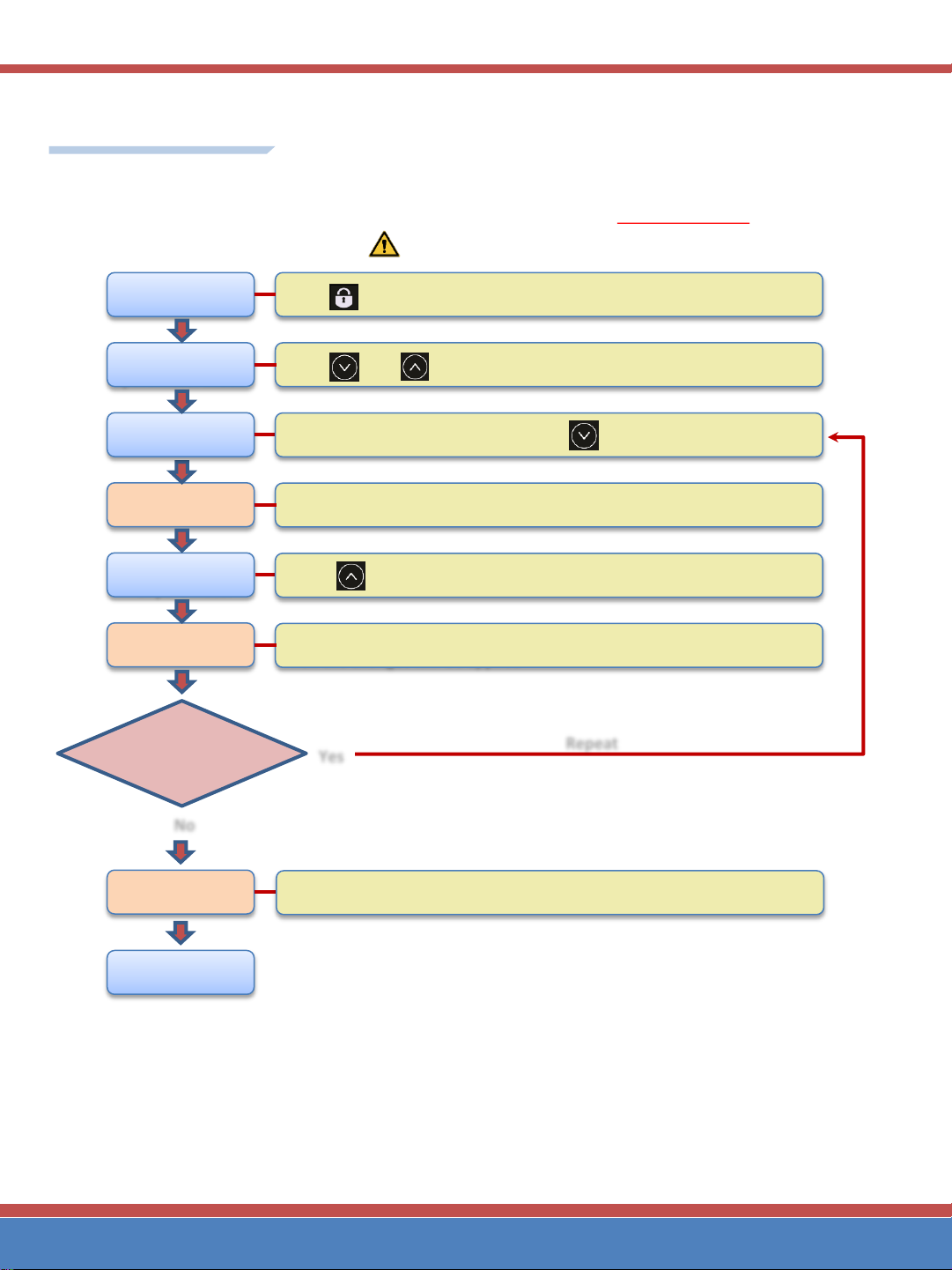
5. CONDENSER CLEANING
①
Disconnect power to unit
②
Take off rear cover at the bottom by removing screws.
③
Clean off accumulated dirt from condensing coil and fan blades with a soft brush.
Make sure to brush in the direction of the fins and not across them to avoid any damage.
④
After brushing condenser coil, vacuum dirt from coil and interior floor.
⑤
Reinstall rear cover onto unit.Tighten all screws.
⑥
Connect unit to power and check to see if compressor is running.
WARNING -To reduce the risk of electric shock, unplug before
cleaning or servicing.
CLEANING
1. POWER CORD
- Make sure the power cord is connected to the proper voltage.
- Compressor warranties are void if compressor burns out due to improper voltage.
- A protected circuit of the correct voltage and amperage must be used for connection of the power cord.
-Turn 'off ' the power switch before disconnecting the power cord whenever performing
maintenance functions or cleaning the refrigerated cabinet.
- If the power cord of the unit is damaged, it should be replaced by an authorized service agent.
2. RE-STARTING
- If disconnected, wait 5 minutes before re-starting.
Caution
Condensing coil & fan blades

Parameter Setting
Exit Setting
Unlock buttons
Touch and buttons at a same time until display shows “nd”
Access to
parameter mode
Wait
Touch button for 3 seconds.
Leave it for 1 second until display shows the value of parameter.
Adjust the value
of parameter
Select Parameter Select the parameter you desire by touch button.
Touch button repeatedly until display shows the value you desire.
Wait Leave it for 3 seconds until display goes back to parameter mode.
Then the changes will be applied
Wait
Need to set ot
her parameter
s ? Yes
No
Leave it for 5 more seconds, Then buttons will be locked automatically.
Repeat
Follow the steps to set the value of parameter.
Gently touch the button and Do Not press hard because
the operation of the button is done by the electrostatic m
ethod.
UNDERCOUNTER / Guide to set parameters for R290 UNIT

Default Value of Parameter
No
Para
-meters
Function Control or Range of
control
Table Units
Remarks
REF FRZ
KUCR
KST/KSTM
KUCR-72-3
KST-72-3
KSTM-72-3
KUCF
1
nd
Model Code
See the table below
Not recommended
to change.
UCr UCS UC7 UCF
Factory use Only
2
dS
Forced Defrost,
When select “dF”
dS ; Normal operation
dF ; Forced Defrost
dS dS dS dS
3
oF
Cabin Temperature
Calibration
“-
50 ~50” 10 10 0 10
Factory or Service
technician use Only
4
od
Differential for set point
“025~50”
10 10 10 10
5
CA
Cabin Sensor
Calibration
“-
50~50” -10 -10 0 -10
Factory or Service
technician use Only
6
dp
Display temperature
calibration
“1~10”
4 4 4 4
Factory use Only
7
dt
Interval between defrost
cycles
“0,5,6,7,8,9,10” Hr(s)
5 5 5 8
8
nt
Maximum Defrost
interval control
“0~99”
N/A N/A N/A 8
Factory use Only
9
dC
Defrost termination
Temperature control
“10~20
°C”
Control by
°C only N/A N/A N/A 12
10
Ht
Cord Heater ON/OFF c
ontrol
“OF,1,2,3,
-1,-2,-3,ON” -2 -2 -2 -2
Factory use Only
11
Fn
Evaporator fan control
Co ;
runs continuously
“--
” ;
runs with the comp
-- Co Co --
12
Ld
Light ON/OFF control
OFF; Light
ON or OFF
by door switch
ON; ON continuously
OFF OFF OFF OFF
13
UFn
Vaporizer fan set
OFF; For the model doesn’t
have Vap Fan
ON ;
For the model has
Vap Fan
OFF OFF OFF OFF
Factory or Service
technician use Only
14
Cr
Alarm
interval for
cleaning condenser coil
“0,3,6,9” months
0 0 0 0
15
dd
Display by every
(0.1,0.5, or 1 ℉/℃)
“01,05,10”
10 10 10 10
Factory use Only
16
HL
Maximum set point
FRZ;
-22 ~ 32°F
REF; 23 ~ 59
°F 40 40 40 6
17
LL
Minimum set point
FRZ;
-22 ~ 32°F
REF; 23 ~ 59
°F 33 33 33 -10
18
CF
Measurement unit
"℃"
or "℉”
Display will show
"℃" or "℉”
F F F F
19
Er
Error test mode
See the following instruc
tion for more details
Factory use Only
20
tE
Test Mode
Factory use Only
21
EC
Parameter reset to Defa
ult at factory
Factory use Only
Terms :
•REF ; Refrigerator
•FRZ ; Freezer
•BOT ; Bottom mounted compressor model
•TOP ; Top mounted compressor model
•Vap Fan ; Vaporizer Fan [for condensate water]
◈See the following instruction for more details.
<Blue air>
UNDERCOUNTER / Guide to set parameters for R290 UNIT

Details of Parameter
nd Select a program by model.
•It is not recommended to change. Keep the default.
Changes may invalidate the warranty.
ds Defrost Control
•dS default –operation in normal.
•dF Perform defrost 5 sec after it is selected.
oF Cabin temperature control : Factory use Only.
Unit will be controlled with Set Temp + oF value
Od Differential, Intervention deferential for set point,
Compressor cut in is Set Point + Od value and cut out
is Set Point - Od value.
CA Calibration of the temperature difference between
the actual temperature of cabinet and the temperatur
e of display. The display will show “Sensing tempera
ture + the value of CA.
dp Temperature sensor calibration :Factory use Only.
•keep the default.
dt Interval between defrost cycles.
•0,5,6,7,8,9,10 Hour(s) can be selected.
nt Maximum Defrost interval control. :Factory use Only.
•keep the default.
Code Value Code Value Code Value
"00" 0 "-35"
-6.3°F " 35"
6.3°F
"- 5" -0.9°F "-40"
-7.2°F " 30"
5.4°F
"-10"
-1.8°F "-45"
-8.1°F " 25"
4.5°F
"-15"
-2.7°F "-50"
-9.0°F " 20"
3.6°F
"-20"
-3.6°F " 50"
9.0°F " 15"
2.7°F
"-25"
-4.5°F " 45"
8.1°F " 10"
1.8°F
"-30"
-5.4°F " 40"
7.2°F " 5" 0.9°F
UCr
KUCR
-27,36,48,60-***
UCS
KST/KSTM28,36,48,60
-***
UC7
KUCR/KST/KSTM72
-***
UCF
KUCF28,36,48,60
-***
Code Value Code Value
"025" ±0.45°F " 20" ±3.6°F
"050" ±0.9°F " 30" ±5.4°F
"075" ±1.35°F " 40" ±7.2°F
" 10" ±1.8°F " 50" ±9.0°F
" 15" ±2.7°F
Code Value Code Value
" 00" 0 " 50" 9.0°F
"-10" -0.9°F " 40" 7.2°F
"-20" -3.6°F " 30" 5.4°F
"-30" -5.4°F " 20" 3.6°F
"-40" -7.2°F " 10" 1.8°F
"-50" -9.0°F
dc Defrost termination temperature control.
•10~20°C (Controlled by °C base only)
Ht Cord Heater ON/OFF time control : Factory use Only.
•keep the default.
Fn Evaporator Fan operation control
•Co; runs continuously except door open.
•-- ; runs with the compressor.
Ld Light control
•OFF ; Turns ON or OFF by the door switch.
•ON ; Turns ON continuously.
UFn Light control
•OFF; For the model doesn’t have Vap Fan.
•ON ; For the model has Vap Fan.
Cr Alarm interval for cleaning condenser coil.
•Kicks on by the interval selected.(0,3,6,9 Months)
Touch and buttons at a same time to turn it of
f.
Make sure the condenser coil clean before it.
HL Maximum set point ; FRZ; -22 ~ 32°F, REF; 23 ~ 59°F
LL Minimum set point ; FRZ; -22 ~ 32°F, REF; 23 ~ 59°F
dd Temperature display steps by the value selected.
01 = 0.1°F, 05 = 0.5°F, 10 = 1.0°F
CF Measurement unit °C or °F.
Er Error check mode.
If there are no errors, “no” is displayed. If the produc
t has problems, display the error code in turn on th
e display.
See the error code table.
tE Test mode
Each time you select a code, you can check the oper
ation status of the corresponding part. See the test c
ode table.
EC After 1 second after “EC" is displayed, all parameters
are reset to initial default state.
Code
Heater ON / OFF time (min)
Difference between cabin te
mperature(T1) and Ambient t
emperature(T2), X=|T1-T2|
X=10
↓
20↓
30↓
40↓
50↓
60↓
60↑
"OF"
Cord Heater is OFF
1
14/20
12/10
21/7
45/5
ON
ON
ON
If the cabin temperature is hig
her than 76
°
F, the cord heat
er remains on.
When the temperature is 76 °
F or below, the heater operat
es according to the time (ON /
OFF) of the table.
2
11/20
10/10
16/7
26/5
90/5
ON
ON
3 9/20
8/10
12/7
17/5
45/5
ON
ON
-1 7/20
7/10
9/7
12/5
28/5
90/5
ON
-2 5/20
5/10
7/7
8/5
15*5
28/5
90/5
-3 4/20
4/10
5/7
5/5
9/5
18/5
45/5
0 2/20
3/10
3/7
3/5
5/5
11/5
28/5
"ON"
Cord Heater is ON continuously
UNDERCOUNTER / Guide to set parameters for R290 UNIT

Error Code Table
Error
Code
Cause Error Conditions Display before accessing
Error Check mode Status of Unit
"S1 "
Defective
Temperature
(Cabin)senor
Sensor is disconnected, opened or Cabinet Te
mperature is below
-58°F
ESL
Show "ESL" on display with alarm sou
nd(beep)
"S1_"
Defective
Temperature
(Cabin)senor
Sensor is shorted or Cabinet Temperature is ab
ove 149
°F
ESL
"rt "
Defective
Ambient
Temperature
sensor
Sensor is disconnected or opened
Shows cabin temperature
Recognizes the ambient temperature
as 90
°F and operates normally.
"rt_"
Defective
Ambient
Temperature
sensor
Sensor is shorted
Shows cabin temperature
"D1 "
Defective
Defrost Sensor
Sensor is disconnected, opened or Cabinet Te
mperature is below
-58°F
Shows cabin temperature
or display "tO"
"D1_"
Defective
Defrost Sensor
Sensor is shorted or Cabinet Temperature is ab
ove 149
°F
Shows cabin temperature
or display "tS"
"dF1"
Fail to defrost
Defrosting time is more than 50 minutes
Shows cabin temperature
"CF1"
Fail to cool
30 minutes after Comp operation,
if the defrost sensor is sensing 32
°
F or above,
Shows cabin temperature
"EHF"
Freezer cabin temperat
ure high
If the cabin temperature is above 45
°
F for 8 hou
rs after the compressor starts up
Shows cabin temperature
"EHr"
Refrigerator cabin temp
erature high
If the cabin temperature is above 45
°
F for 8 hou
rs after the compressor starts up
Shows cabin temperature
"Edr"
Door Open
When Door is open for more than 1 hour
(Door Switch)
Edr
Alarm (Beeping sound)
"EF1"
E-FAN1 Error
When evaporator fan is not running
EF1
Alarm (Beeping sound)
"Ufn"
V-FAN Error
V
-
FAN is disconnected, opened or not running.
Ufn"
Alarm (Beeping sound)
Test mode
Code Test Time or Display Test what Remarks
"St" 10 Sec Stand by REF/FRZ
"CP1" Continuous Comp/Fan ON REF/FRZ
"dHt" Continuous Defrost Heater ON FRZ
Only
"CHt" Continuous Code Heater ON REF/FRZ
"LP" Continuous Light ON REF/FRZ
"rS" Display "rS" Cabin sensor REF/FRZ
"rt" Display "rt" Ambien Sensor REF/FRZ
"ds" Display "ds" Difrost sensor REF/FRZ
UNDERCOUNTER / Guide to set parameters for R290 UNIT

10
Trouble-Shooting
Problem
Possible Cause Action
Compressor not working
Power connection failure Check Power Cord and
plug it in
Power switch is in off position Change it on position
The unit does not
refrigerate well
Temperature set point is
too high
Correct temperature set
point
The door is opened
too frequently
-
Loading of too much warm
or moist product
-
Not enough ventilation
Move the unit in a well
Ventilated place with at
least 7
Inches of clearance on all
sides
Condenser is clogged Clean it
Condensation
on cabinet exterior
High humidity can cause
surface condensation. Also,
make sure that the door
seals are clean and in good
condition.
Wipe with cloth
◆
A water-flowing sound can be heard when the unit is operating.
This is the sound of refrigerant flowing.

11
Installing Castors
1. Remove the outer packing.
2. Install the castors as illustrated.
3.
Maker sure that the castors with brakes are installed at the front of the unit.

Printed May 2020
warranty
MVP GROUP CORPORATION
5659 Royalmount Ave. Montreal, QC, Canada H4P 2P9
Telephone : (514) 737-9701
Toll FreeTelephone : (888) 275-4538
Fax : (514) 342-3854
Toll Free Fax : (877) 453-8832
Email : service@mvpgroupcorp.com
Website : www.mvpgroupcorp.com
THREEYEAR PARTS & LABOR WARRANTY
MVP GROUP CORP. (KOOL-IT) warrants to the original purchaser of every new KOOL-IT refrigerated unit to be free
from defects in material or workmanship, under normal and proper use and maintenance service as specified by
MVP Group Corp. and upon proper installation and start-up in accordance with the instruction packet supplied with
each unit. MVP Group’s obligation under this warranty is limited to a period of three (3) years from the date of
original installation.
Any original part covered under this warranty that is determined by MVP Group Corp. to have been defective within
three (3) years of original installation shall be limited to the repair or replacement, including the labor charge for
defective parts or assemblies.The labor warranty shall include standard straight time labor charges only and
reasonable travel time, as determined by MVP Group Corp.
Warranty shall not cover standard wear and tear parts which include door gaskets, incandescent bulbs, LED lamps,
or fluorescent bulbs. Warranty also does not cover issues caused by improper installation or lack of basic
preventative maintenance which includes, but not limited to regular cleaning of condenser coils.
ADDITIONALTWOYEAR COMPRESSOR WARRANTY
In addition to the three (3) year warranty stated above, MVP Group Corp. hereby warrants its hermetically and semi-
hermetically sealed compressors to be free from defects in both material and workmanship under normal and
proper use and maintenance service for a period of two (2) additional years from the date of original installation,
but shall at no times exceed five (5) years after shipment from the manufacturer.
Compressors determined by MVP Group Corp. to have been defective within this extended time period will, at MVP
Group Corp’s option, be either repaired or replaced with a compressor or compressor parts of a similar capacity.
The two (2) year extended compressor warranty applies only to hermetically and semi-hermetically sealed parts of
the compressor and does not apply to any other parts of components, including but not limited to: cabinet, paint
finish, temperature control, refrigerant, metering device, driers, motor starting equipment, fan assembly or any
other electrical component, Etc.
12000 Biscayne Blvd. Ste 108 Miami,
FL 33181
Telephone: (786)-600-4687
Toll Free Telephone: (844)-218-8477
Fax:(786)-661-4100
This manual suits for next models
18
Table of contents
Other Kool-It Commercial Food Equipment manuals
Popular Commercial Food Equipment manuals by other brands

Sigma
Sigma CHEF 10 Use and maintenance instruction manual

Federal
Federal SN4HD Installation & operation instructions

PENTAGAST
PENTAGAST cookmax CXGFTA498R/900 operating instructions

Fagor
Fagor CP-G7126 Installation, Usage and Maintenance Instructions

Italian Gelato
Italian Gelato CARESS instruction manual

Garland
Garland G12-2TCG Installation and operation manual