Kopp GCM 221 User manual

Digitaler Zangenamperemeter
Bedienungsanleitung
Autoranging Digital Clamp Meter
Owners Manual
Medidor de abrazadera digital de
autoreglaje
Manual del propietario
Pince ampèremétrique
Manuel d’utilisation
Digitale ampèremeter
Gebruiksaanwijzing
Amperometro digitale a pinza
Manuale d‘istruzioni
• Bitte die Bedienungsanleitung
vor Gebrauch sorgfältig durchlesen.
• Read this owners manual
thoroughly before use and save.
• Lea atentamente este manual
del propietario antes de
utilizar y guardar.
• Lisez ce manuel entièrement
avant utilisation et rangez-le
soigneusement.
• Lees deze gebruiksaanwijzing
aandachtig door voordat u het product
gebruikt en bewaar hem.
• Si prega di leggere attentamente il
presente manuale prima dell‘uso.
GCM 221
1990.0702.6

Inhalt
Seite 2 Funktionen
Seite 3 Technische Angaben
Seite 4 Sicherheitshinweise
Seite 4 Hinweise zum Betrieb
Seite 4 Geräteübersicht
Seite 5 Widerstandsmessung
Seite 5 Durchgangsprüfung
Seite 6 Messen von Wechselspannung
Seite 6 Messen von Wechselstrom
Seite 7 Batteriewechsel
Funktionen
Strommesszange
Sicherheits-
Schutz-Ring
Zangenöffner
LCD Display
Buchse „COM“
Taste zum
Einfrieren des
Messwertes
Funktionsauswahl-
Funktionsauswahl-
Funktionsauswahl-
Drehschalter
Buchse „+“
Funktionsauswahl-
Buchse „COM“
Zangenöffner
Sicherheits-
2

Technische Angaben
Messbereich:
Automatische Bereichseinstellung
Max. Wechselspannung:
600 V
Max. Wechselstrom:
600 A
Max. Widerstandsmessung:
200 Ohm
Messgenauigkeit:
Wechselspannug +/- 1.5%
Wechselstrom +/- 2.0%
Widerstand +/- 1.0%
Funktionen:
4 Funktionen
4 Drehschalterpositionen
Max. Messrate:
2 Messungen/sek.
Betriebstemperaturbereich:
0°C - 40°C
Lagerungstemperaturbereich:
0°C - 60°C
3,5 stelliges LCD Display
Versenkte Eingangsbuchsen:
„COM-Eingangsbuchse (-) für die schwarze Messleitung,
+ Eingangsbuchse für die rote Messleitung“
Batterien:
2x „AAA“
Wichtig:
„Lesen Sie diese Betriebsanleitung sorgfältig durch, bevor Sie
das Meßgerät verwenden. In der Anleitung sind grundlegende
Hinweise zum Betrieb des Meßgerätes enthalten. Regeln der
Elektrotechnik beachten!“
Warnung:
Lassen Sie beim Gebrauch dieses Messgerätes extreme Vorsicht
walten. Unsachgemäßer Gebrauch kann zu Beschädigungen des
Messgerätes selbst, von zu messenden Geräten, Personenschä-
den bis hin zum Tode führen. Folgen Sie den Anweisungen in der
Betriebsanlei tung und beachten Sie die Regeln der Elektrotech
nik.
3

Sicherheitshinweise
1) Lassen Sie beim Gebrauch dieses Messgerätes extreme
Vorsicht walten.
2)
Warnung!
Führen Sie Messungen nur in trockener Umge-
bung durch. Tragen Sie Isolationsschuhe und entsprechen-
de Schutzkleidung.
3)
Warnung!
Legen Sie niemals mehr Spannung oder Strom an
das Messgerät, als in den technischen Daten angegeben.
4)
Warnung!
Berühren Sie während des Messvorganges nicht
die Metallteile der Messspitzen.
5) Tauschen Sie defekte oder beschädigte Messleitungen
unverzüglich aus.
6) Bei Kondensatormessung ist dieser vorher zu entladen.
7) Die Messleitungen sofort nach dem abgeschlossenen Mess
vorgang entfernen.
8)
Warnung!
Legen Sie keinerlei Strom oder Spannung an,
wenn der Funktionsauswahl-Drehschalter auf Position
„Ohm“ gerichtet ist. Eine falsch gewählte Meßfunktion kann
zu Beschädigung des Meßgerätes führen und die Sicherheit
gefährden.
Hinweise zum Betrieb
1) Vor Beginn des Meßvorganges den Funktionsauswahl-Dreh-
schalter auf die richtige Posotion stellen. Falls die zu erwar-
tende Höhe der Spannung oder des Stromes nicht bekannt
ist, muss sichergestellt sein, dass der eingestellte Messbe-
reich nicht überschritten wird. (Bitte hierzu Punkt 3 beach-
ten: - Sicherheitshinweise)
2) Vermeiden Sie die Verwendung des Messgerätes wenn
dieses dabei Vibrationen, Staub oder Schmutz ausgesetzt
sein würde.
3) Die Verwendung in Bereichen mit starken Magnetfeldern
kann zu ungenauen Messergebnissen führen.
4) Tauchen Sie das Messgerät nicht in Flüssigkeit ein. Zur
Reinigung der Geräteoberfl äche ein feuchtes Tuch mit gerin-
ger Menge milder Seife verwenden
Geräteübersicht
Symbolerklärung:
Messwert OHM ausgewählt
Strom ausgewählt
Spannung ausgewählt
Durchgang ausgewählt
Messwertspeicherung aktiv
schwache Batterie
AC Symbol
4

Widerstandsmessung
Den Funktionsauswahl-Drehschalter auf Symbol
„OHM“
stellen.
Die rote Messleitung in die mit „+“ gekennzeichnete Buchse,
und die schwarze Messleitung in die mit „COM“ gekennzeich-
nete Buchse stecken. Die Messspitzen mit den zu messenden
Punkten verbinden. Das Messergebniss ablesen.
Beachten:
Auf Spannungsfreiheit achten und Kondensatoren vor der
Messsung entladen.
Durchgangsprüfung
Den Funktionsauswahl-Drehschalter auf Symbol „OHM“
stellen. Die rote Messleitung in die mit „+“ gekennzeichnete
Buchse, und die schwarze Messleitung in die mit „COM“
gekennzeichnete Buchse stecken. Die Messspitzen mit den
zu messenden Punkten verbinden. Falls der Widerstand unter
100ž liegt, ist ein Signalton zu hören.
5

Messen von Wechselspannung:
Beachten:
Spannungsmessungen können nur mittels der
Messleitungen vorgenommen werden, nicht mit der Strom-
zange. Den Funktionsauswahl-Drehschalter auf Symbol „V~“
stellen. Die rote Messleitung in die mit „+“ gekennzeichnete
Buchse, und die schwarze Messleitung in die mit „COM“
gekennzeichnete Buchse stecken. Die Messspitzen mit den zu
messenden Punkten verbinden. Das Messergebniss ablesen.
Messen von Wechselstrom
Den Funktionsauswahl-Drehschalter auf Symbol „A~“ stellen.
Die Stromzange öffnen und die Leitung umfassen. Die Zange
schließen und den Meßwert ablesen.
Hinweis:
Niemals mit der Stromzange zwei Leitungen gleichzeitg um-
schließen. Nur um eine Leitung legen. Eine andere Handha-
bung hat ein unbrauchbares Meßergebniss zur Folge.
Hinweis:
Falls Sie aus Platzgründen das Display während der Messung
nicht ablesen können, drücken und halten Sie die „Hold“-Taste
um das Messergebniss „einzufrieren“.
RICHTIG
FALSCH
6

Batteriewechsel
1. Falls die Batteriekapazität unter einen Wert fällt, der die
Betriebsfähigkeit nicht mehr sicherstellt, erscheint das Bat-
teriesymbol auf dem LCD-Display. In diesem Fall die
Batterie sofort austauschen.
2. Vor dem Batteriewechsel das Gerät ausschalten (OFF) und
eventl. angeschlossene Messleitungen entfernen. Die Gerä-
terückseite durch entfernen der beiden Kreuzschlitzschrau-
ben öffnen. Batterieersatz mit 2x „AAA“-Batterien.
3. Schließen Sie die Geräterückseite, anschließend die beiden
Schrauben einsetzen und festdrehen.
7

Contents
Page 8 Meter Functions
Page 9 Specifi cations
Page 10 For Your Safety
Page 10 Operating Suggestions
Page 10 Instrument Familiarization
Page 11 Measuring Resistance
Page 11 Testing Continuity
Page 12 Measuring AC Volts
Page 12 Measuring AC Amps
Page 13 Changing The Battery
Meter Functions
Current Sensing Clamp
Safety protection
ring
Clamp opening
handle
LCD display
COM input terminal
Data hold
button
Function
select dial
Positive input terminal
8
button
Safety protection

Specifi cations
Ranges:
Autoranging
AC Voltage:
600 Volts
AC Current:
600 Amps
Resistance (Ohms):
200 Ohms
Accuracy:
AC voltage +/- 1.5%
AC current +/- 2.0%
Resistance +/- 1.0%
Function/Range switch:
4 functions
4 positions
Sample Rate:
2 times / sec
Operation Temperature:
32oF - 104oF (0oC - 40oC)
Storage Temperature:
14oF - 140oF (-10oC - 60oC)
31/2 Digit LCD Display
Recessed Input Jacks:
Negative (-) input jack for black test lead, positive (+) input
jack for red test lead.
Batteries:
Two - „AAA“
Important:
Read this operators manual thoroughly before using this
meter. This manual is intended to provide basic information
regarding this meter and to describe common test procedures
which can be made with this unit. Many types of appliance,
machinery and other electrical circuit measurements are not
addressed in this manual and should be handled by experi-
enced service technicians.
Use extreme caution when using this meter. Improper use of
this meter can result in severe damage to property, severe per-
sonal injury or death. Follow all instructions and suggestions
in this operators manual as well as observing normal electrical
safety precautions. Do not use this meter if you are unfamiliar
with electrical circuits and proper test procedures.
9

For Your Safety
1) Use extreme caution when checking electrical circuits.
2)
Warning!
Do not stand in wet or damp work areas when
working with electricity. Wear rubber-soled boots or shoes.
3)
Warning!
Do not apply more voltage or current than the set
range of the meter will allow.
4)
Warning!
Do not touch the metal probes of the test leads
when making a measurement.
5) Replace worn test leads. Do not use test leads with broken
or tattered insulation.
6) Discharge a capacitor before measuring it.
7) Remove the test leads from the circuit being measured as
soon as the test is completed.
8)
Warning!
Do not measure voltage when the function/range
switch is set on the resistance (ohms) range. Never measure
current when the meter is set on the resistance range.
Setting the meter on the incorrect function may burn out
some of the internal circuitry and may pose a safety hazard.
Operating Suggestions
1) Set the function/range switch to the proper position before
making a measurement. When the voltage or current is
not known, it MUST be determined that the capacity of the
selected range will handle the amount of voltage or current
in the circuit (see #3 under For Your Safety).
2) Avoid placing the meter in areas where vibration, dust or
dirt are present. Do not store the meter in excessively hot,
humid or damp places. This meter is a sensitive measuring
device and should be treated with the same regard as other
electrical and electronic devices.
3) Using the meter in areas with high magnetic fi elds can
result in inaccurate readings.
4) Never immerse the meter in water or solvents. To clean
the housing use a damp cloth with a minimal amount of
mild soap.
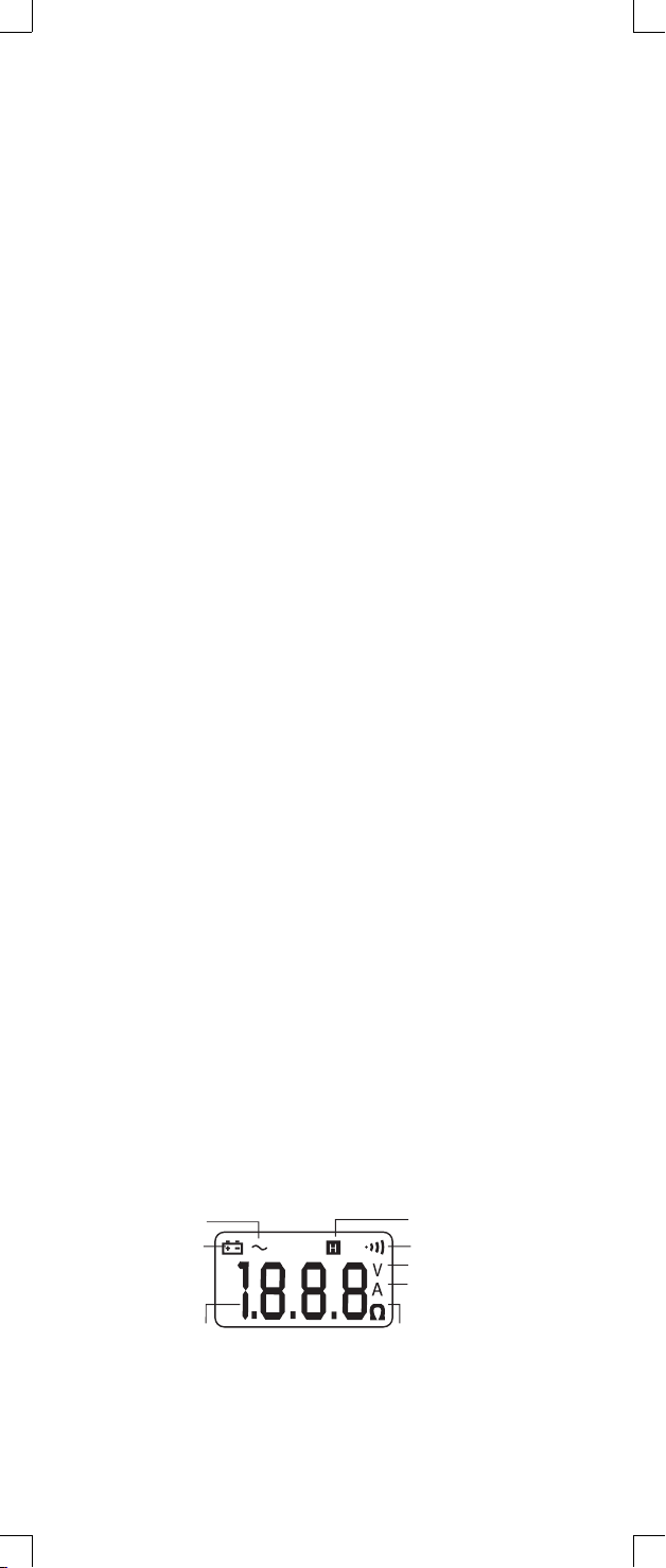
Instrument Familiarization:
Symbol Defi nition:
10

Measuring Resistance:
Switch the function select or to
Ω
range. Connect red test
lead to „+“ terminal and black one to the „COM“ terminal.
Connect tip of the test leads to the points where the value of
the resistance is needed. Read the result from the LCD panel.
Note:
When taking measurements from a circuit, make sure the
power is off and all capacitors are discharged.
Testing Continuity:
Switch the function selector to
Ω
range. Connect red test
lead to „+“ terminal and black one to the „COM“ terminal.
Connect tip of the test leads to the points where tests need
to be made. If the resistance is under 100
Ω
, the beeper will
sound continuously.
11

Measuring AC Volts:
Note:
Voltage measurements can only be made using the test leads
and not the clamp-around jaws.
Switch the function selector to V~range. Connect red test lead
to „+“ terminal and black one to the „COM“ terminal. Measure
the voltage by touching the test lead tips to the circuit where
the value of voltage is needed. Read the result from the LCD
panel.
CORRECT
INCORRECT
Measuring AC AMPS:
Switch the function selector to A~range. Open the jaws by
pressing the handle and insert the cable to be measured into
the jaw. Close the clamp and note the reading on the LCD.
Note:
Never clamp the Jaws around two wires as this will cause
inaccurate readings. Only clamp Jaws around a single wire
— either the HOT or NEUTRAL WIRE.
Note:
When the display is hard to read, push the hold button to
freeze the reading.
12

Changing The Battery:
1. When the battery voltage drops below proper operating
range the symbol will appear on the LCD display and
the battery needs to be changed.
2. Before changing the battery, switch the function selector
to „OFF“ and disconnect test leads. Open the back cover by
removing the two screws. Replace old batteries with two
AAA size batteries.
3. Close the back cover and fasten the screws.
13

Contenidos
Página 14 Funciones del Polímetro
Página 15 Especifi caciones
Página 16 Para Su Seguridad
Página 16 Sugerencias de Funcionamiento
Página 17 Medición de la Resistencia
Página 17 Medición del Voltaje de CA y CC
Página 18 Medición de la Intensidad de CA A
Página 18 Medición de Voltaje CA
Página 19 Medición de la Intensidad CA
Página 19 Cambio de pilas
Funciones del Polímetro
Manivela de
apertura de
abrazadera-
Clamp opening
handle
Interruptor
de retención
de datos
Disposi-
tivo de
selección
de función
Terminal de alimen-
tación positiva
14
Abrazadera sensora de
corriente
Anillo de protec-
ción de seguridad
Dispositivo
visualizador de
pantalla de cristal
líquido
Terminal de alimenta-
ción COM
Interruptor
Manivela de
Anillo de protec-
ción de seguridad

Especifi caciones
Rangos:
Autoreglaje
Voltaje CA:
600 Voltios
Intensidad CA:
600 Amperios
Resistencia (Ohmios):
200 Ohmios
Precisión:
CA Voltaje +/- 1.5%
Intensidad CA +/- 2.0%
Resistencia +/- 1.0%
Interruptor Función/Rango:
4 funciones
4 posiciones
Frecuencia de muestreo:
2 veces / segundo
Temperatura de manejo:
32oF - 104oF (0oC - 40oC)
Temperatura de almacenamiento:
14oF - 140oF (-10oC - 60oC)
3 1¼2 Dispositivo visualizador de pantalla de cristal líquido
de dígito
Clavijas de Entrada Demorada:
Clavija de entrada negativa (-) para el conductor de prueba
negro, clavija de entrada positiva (+) para el conductor de
prueba rojo.
Pilas:
Dos de tipo „AAA“
Importante:
Lea atentamente este manual del operador antes de utilizar
este polímetro. Este manual está orientado a proporcionar la
información básica referente a este polímetro y a describir los
procedimientos habituales que se pueden realizar con esta
unidad. Muchos tipos de medidas de aplicaciones, maquinaria
y otros componentes eléctricos no están reseñados en este
manual y los deberán realizar técnicos de servicio experimen-
tados.
Tenga extremo cuidado cuando utilice este polímetro. El
uso inadecuado de este polímetro puede dar lugar a daños
graves al equipo, daños personales o muerte. Siga todas
las instrucciones y sugerencias de este manual del operador
y observe también las precauciones de seguridad normales
para componentes eléctricos. No utilice este polímetro si no
está familiarizado con los componentes eléctricos y con los
procedimientos de ensayo adecuados.
15

Para Su Seguridad
1) Tenga extremo cuidado cuando compruebe componentes
eléctricos.
2)
Advertencia!
No se coloque en áreas h medas o mojadas
cuando trabaje con electricidad. Lleve botas o zapatos con
suela de goma.
3)
Advertencia!
No aplique más voltaje o intensidad de la que
el rango del polímetro permita.
4)
Advertencia!
No toque las puntas de metal de los conducto
res de prueba cuando se realice una medida.
5) Cambie los conductores de prueba desgastados. No use
conductores de prueba con el aislamiento roto o en mal
estado.
6) Antes de medir un condensador, descárguelo.
7) Retire los conductores de prueba del circuito que se está
midiendo tan pronto como se haya concluido la prueba.
8)
Advertencia!
No mida el voltaje cuando el interruptor
de función/rango esté indicando el rango de resistencia
(ohmios). No mida nunca intensidad cuando el polímetro
esté ajustado para la medida de resistencia. No mida nunca
voltaje de CA cuando el polímetro esté ajustado para voltaje
de CC. Al colocar el polímetro en la función incorrecta, pue-
de quemar algunos de los circuitos internos y puede dar
lugar a un riesgo de peligro de seguridad.
Sugerencias de Funcionamiento
1) Coloque el interruptor de función/rango en la posición
adecuada antes de realizar una medida. Cuando el voltaje
o la intensidad no se conoce, DEBE determinarse de modo
que la capacidad del rango seleccionado pueda soportar
el voltaje o la intensidad del circuito (vea #3 en Para Su
Seguridad).
2) No poner el polímetro en zonas en las que haya vibra-
ción, polvo o suciedad. No guarde el polímetro en sitios
excesivamente calientes, h medos o mojados. Este políme-
tro es un dispositivo de medida sensible y se ha de tratar
con los mismos cuidados que el resto de los dispositivos
electrónicos.
3) Si se utiliza el polímetro en zonas con campos magnéticos
fuertes se pueden producir lecturas no precisas.
4) Nunca sumerja el polímetro en agua o disolventes. Para
limpiar la caja utilice un paño humedecido con una cantidad
mínima de detergente suave.
16

Familiarización con los instrumentos
Defi nición de símbolos:
Medición de la Resistencia:
Conmute el selector de función a
Ω
rango.
Conecte el conductor de pruebas rojo a la terminal positiva y
el negro a la terminal „COM“.
Conecte los extremos de los conductores de pruebas a los
puntos en los que se necesita el valor de la resistencia.
Lea los resultados en el panel de la pantalla de cristal líquido.
Nota:
Cuando se tomen mediciones de un circuito, asegúrese de que
la potencia está desconectada y todos los capacitores estén
descargados.
17

Prueba de continuidad:
Conmute el selector de función a
Ω
rango.
Conecte el conductor de pruebas rojo a la terminal positiva y
el negro a la terminal „COM“.
Conecte los extremos de los conductores de pruebas a los
puntos en los que se necesita hacer las pruebas.
Si la resistencia es inferior a 100 ž, el avisador sonará conti-
nuamente.
Medición de Voltaje CA:
Nota:
La medición de voltaje sólo se puede realizar utilizando las
puntas de prueba, no con las pinzas abrazadera.
Conmutar el selector de función a rango V~.
Conecte el conductor de pruebas rojo a la terminal positiva y
el negro a la terminal „COM“.
Mida el voltaje tocando los extremos de los conductores de
pruebas al circuito en el que se necesita el valor del voltaje.
Lea los resultados en el panel de la pantalla de cristal líquido.
18

Medición de la Intensidad CA:
Conmute el selector de función a rango A~.
Abra las mordazas presionando la manivela e introducir el
cable que desea medir en la mordaza.
Cierre la abrazadera y anote la lectura de la pantalla de cristal
líquido.
Nota
:
Nunca fi je las mordazas en torno a dos cables ya que esto
causaría lecturas inexactas. Fije solamente mordazas en torno
a un único cable - bien sea el CABLE CON CORRIENTE o el
NEUTRO.
Nota:
Cuando el dispositivo visualizador sea de difícil lectura,
presione el botón de parada para congelar la lectura.
CORRECTO
INCORRECTO
Cambio de pilas:
1. Cuando el voltaje de las pilas caiga por debajo del rango
de funcionamiento adecuado el símbolo aparecerá en el
dispositivo visualizador de la pantalla de cristal líquido y
será necesario cambiar
2. Antes de cambiar las pilas, conmute el selector de función
a la posición „OFF“ y desconecte los conductores de prue-
bas. Abra la tapa trasera retirando los dos tornillos. Sustitu-
ya las pilas viejas
3. Cierre la tapa trasera y apriete los tornillos.
19

Table des matières
Page 20 Fonctions du multimètre
Page 21 Caractéristiques
Page 22 Consignes De Sécurité
Page 22 Suggestions d‘Utilisation
Page 23 Mesurer une Résistance
Page 24 Mesurer les Volts Alternatifs et Continus
Page 24 Mesurer les Ampères Alternatifs
Page 24 Mesure des tensions alternatives
Page 25 Mesure du courant alternatif (A)
Page 25 Remplacement des piles
Fonctions de l‘appareil de mesures
Pince ampèremétrique
Anneau de
protection
Poignée
d‘ouverture
de la pince
Affi cheur
à cristaux
liquides
Borne d‘entr’ee COM
Bouton de
stockage
des don-
nées
Cadran du
sélecteur
de fonction
Borne d‘entrée du
Positif
20
des don-
Table of contents
Languages:
Other Kopp Measuring Instrument manuals