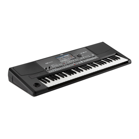
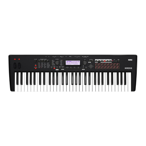
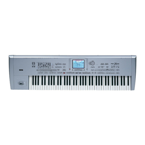
Korg PA 500 User manual

KORG Pa500
SERVICE MANUAL
TABLE OF CONTENTS
ASSEMBLY SKETCH (HOOKUP): 2-3
BLOCK DIAGRAM: 4
SCHEMATIC DIAGRAM: 5-12
TEST MODE: 13-26
PARTS LIST: 27-30
Issued:Nov.15, 2007
Ver1.0

Pa500 ASSEMBLE DRAW UPPER DRAW
Screw information
Part Cord PART NAME NOTE
510700503509 BT B 3BC 3 X 6 for metal chassis to PCB
510700503563 SCREW BT B 3BC 3X10 for UPPER CASE
510700503574 BT FEW 3BBC 3 X 16 for KEY BORAD
510700503512 SCREW BT B NIC 3 X 8 for rear side UPPER CASE

Pa500 ASSEMBLE DRAW BOTTOM SIDE DRAW
Part Cord PART NAME NOTE
510700503613 BT FEW 3BC 3 X 20 for bottom board
510700503614 BT B 3BBC 4X20 for UPPER side & BOTTOM side
No Part Cord PART NAME NOTE
510646508002 X-5390 UPPER CASE E10252-1 Standerd Pa500
- X-539A UPPER CASE E10252-2
- X-539B UPPER CASE E10252-3
- X-539C UPPER CASE E10252-4
- X-539D UPPER CASE E10252-5
- X-539E UPPER CASE E10252-6
- X-539F UPPER CASE E10252-7
2510646502086 KEY ASSY 13(M) KOC-H30306-1
3510646502085 KEY ASSY 12(M) KOC-H30305-1
4510500505001 KEY GUIDE RUBBER QMGG055AA
5510500505501 KB FELT 1 KOC-F41281-1
6510649500502 PA50 JS ASSY 11PA050JS10
7510500504503 RUBBER BOTTON 13 KOC-E30438
8510640508028 X-5390 SH SPRING C41536
9510646502122 X-952 PWS KNOB (CH) E40726
10 510640508031 X-5390 LOWER CHASSIS C30753
11 510640508030 X-5390 UPPER CHASSIS C30752
12 510646502119 X-5390 LCD HOOD E30475
13 510802500534 X-5390 SP NET C30754
14 510646502049 X-2100 SLIDER KNOB E40578-2
510646508501 5390 SQUARE SW NL DG E40720-1 collor:Dark GRAY
510646508502 5390 SQUARE SW NL LG E40720-2 collor:Light GRAY
510646508503 5390 SQUARE SW LED DG E40721-1 collor:Dark GRAY
510646508504 5390 SQUARE SW LED LG E40721-2 collor:Light GRAY
510646508505 5390 SQUARE SW LED RD E40721-3 collor:RED
17 510646502123 X-610 ENCODER KNOB(CH) E40727 -1 GRAY
18 510646508001 X-5390 BOTTOM CASE E20294
19 510646502120 X-5390 BASS PORT assy L E30476-1
20 510646502121 X-5390 BASS PORT assy R E30476-2
21 510645500005 X-5390 BOTTOM BOARD L D30312
22 510645500006 X-5390 BOTTOM BOARD R D30313
23 510802500533 X-5390 FOOT RUBBER E40723
15
16
1

How to enter the TEST MODE
<<Start the TEST MODE>>
Pressing the [STYLE PLAY] and the [MEDIA], turn the power on, and continue to pressing until the service
menu is displayed. Confirm that big noise is not heard when power on.
After the service menu is displayed, press the [PAD 2] to start the TEST MODE.
When the service menu is displayed, you can adjust the contrast of the LCD, by pressing the [MENUE],
and rotating the [TEMPO/VALUE] encoder.
TEST MODE DISPLAY
When the service menu is displayed, you can adjust the contrast of the LCD, by
pressing the [MENUE], and rotating the [TEMPO/VALUE] encoder.
<<LCD CALIBRATION>>
This calibration is for the touch panel. At the left side top in the LCD the icon of arrow is displayed.
TOUCH PANEL CALIBRATION START of TEST MODE
After you touch the arrow icon, the arrow mark moves top-left -> bottom –right ->top-right ->
bottom-left. Touch each arrow. When you touch the bottom-left arrow, [save] is displayed in the
LCD, then touch it. The data of calibration is saved and the display becomes START of TEST
MODE. Confirm that SD card is not inserted, push the [JUMP] switch. Test menu is displayed.
Arrow I
con

<<TEST MENUE>>
Touch one item to check.
item Check
[Nand] Internal: Check of NAND
[TGL] Internal: Check of TGL, PCM ROM
[Usb Device] Internal: Check of USB
[MMC/SD Card] Internal: Check of SD Card
[Midi Loop] Internal: Check of MIDI Loop
[Touch Panel] Check of Touch Panel
[Panel Buttons] Check of switches and LEDs
[Sliders] Check of A/D mute
[Audio Output] Check of Maximum Output and frequency response
[Audio Input] Check of Line input
[Distortion] Check of distortion
[Noise] Check of noise level
[Keyboard] Check of keyboard
[Speakers] Check of speakers
When you start from an item before MIDI Loop, please connect MIDI IN and MIDI OUT by a MIDI
cable.
<<Internal Check: NAND - MIDI Loop>>
When you touch the icon of the internal check, Pa500 execute the internal check
automatically. When some error is detected Pa500 displays the error item in the LCD.

After following display is appeared, insert the SD card. When the SD card is inserted before the
SD Card Check, it is NG. After following display is appeared, insert the SD card then Pa500
begins internal check. When all items of the internal check are OK, the check proceeds to the
check of the touch panel automatically.
The USB check is always NG, so touch the [Next] icon to skip the check.
1:NAND CHECK
2:TGL CHECK
3:USB CHECK
4:SD CARD CHECK
5:MIDI CHECK
Display of request of SD Card insertion
Do not use the card which is used in the SD card Check for other purpose.
<<Check of Touch Panel>>
After the internal check passed, the check proceeds to the check of the touch panel
automatically. Touch the ①・②・③ (see next page) points in the display and confirm following
items.
*The values of [LCD X value], [LCD Y value] when you touch the 3 points is not “0” or “256”.
*The value of [LCD X value] becomes bigger by the order of ①->②->③.
* The value of [LCD Y value] becomes smaller by the order of ①->②->③.
*When you touch the LCD, the mark appears at the [MOVE] icon.
*When you remove your finger from the LCD, the mark appears at the [OFF] icon.

When you touch the LCD, the mark appears for a while at the [ON] icon, but soon it move to the
[MOVE] icon. Confirm the [MOVE] and the [OFF] icons.
After confirmed them, rotate the [TEMPO/VALUE] encoder to the top-center position, then
touch the [Next] icon.
Display of the touch panel check
<<Check of Switch, Encoder, Headphones>>
Touch the [Next] icon to proceed to the check of switches, encoder, headphones.
The display of next page appeared, confirm that the [√] mark is not with the [Headphone] icon.
Then insert the headphone plug to the headphone jack. Confirm that the [√] mark is with the
[Headphone] icon.
Next, rotate the encoder for one around clockwise, confirm that the value of [Wheel:] icon
becomes “24(+). Then rotate the encoder for one around counter clockwise and confirm that the
value of the [Wheel:] icon becomes “0(-).
Next check is switches. All LEDs turned on, confirm that there is not the unevenness of
brightness. The switch which is checked is displayed in the LCD. The order is in the following
table. Confirm that the LED which is checked turned ON, and press the switch to proceed to the
next.
At the time confirm that the check proceeds to next, sound is heard, the color is right, normal
click feeling. Before pressing the last [TRANSPOSE] switch set the {VOLUME} slider to the
maximum position.

<<Switch, Encoder, Headphones: Display>>
LCD Switch LED
1
2
3
4
5
6
7
8
9
10
11
12
13
14
15
16
17
18
19
20
21
ASSIGN SW1
ACCOMP.
MEMORY
MANUAL BASS
EXIT
MENU
STYLE PLAY
SONG PLAY
SEQUENCER
SOUND
GLOBAL
MEDIA
8/16BEAT
POP
BALLAD
BALLROOM
DANCE
ROCK
FUNK&SOUL
JAZZ
STYLE SELECT 1
[ASSIGNABLE SWITCH]
[ACCOMP.]
[MEMORY]
[MANUAL BASS]
[EXIT]
[MENU]
[STYLE PLAY]
[SONG PLAY]
[SEQUENCER]
[SOUND]
[GLOBAL]
[MEDIA]
Dark Gray[8/16BEAT]
Dark Gray [POP]
Dark Gray [BALLAD]
Dark Gray [BALLROOM]
Dark Gray [DANCE]
Dark Gray [ROCK]
Dark Gray [FUNK&SOUL]
Dark Gray [JAZZ]
Dark Gray[STYLE SELECT]
All LEDs light
[ACCOMP.]
[MEMORY]
[MANUAL BASS]
All LEDs light
All LEDs light
[STYLE PLAY]
[SONG PLAY]
[SEQUENCER]
[SOUND]
All LEDs light
All LEDs light
[8/16BEAT]
[POP]
[BALLAD]
[BALLROOM]
[DANCE]
[ROCK]
[FUNK&SOUL]
[JAZZ]
[STYLE SELECT] Upper
Order
Next switch to press
Check Mark
Encoder value
Clockwise(+)
Counter clockwise:(-)

LCD Switch LED
22
23
24
25
26
27
28
29
30
31
32
33
34
35
36
37
38
39
40
41
42
43
44
45
46
47
48
49
50
51
52
53
54
STYLE SELECT 2
RECORD
TRACK SELECT
STS 1
STS 2
STS 3
STS 4
HELP
SHIFT
SOUND SELECT 1
SOUND SELECT 2
PIANO
E.PIANO
ACCORDION
ORGAN
GUITAR
STRINGS & VOC.
TRUMPET
BRASS
PAD 1
PAD 2
PAD 3
PAD 4
STOP
SINGLE TOUCH
SEQ1: SELECT
SEQ1: REW
SEQ1: FFWD
SEQ1: PAUSE
SEQ1: PLAY
SEQ2: SELECT
SEQ2: REW
SEQ2: FFWD
Dark Gray [STYLE SELECT]
Dark Gray [RECORD]
Dark Gray [TRACK SELECT]
Dark Gray [1]
Dark Gray [2]
Dark Gray [3]
Dark Gray [4]
Dark Gray [HELP]
Dark Gray [SHIFT]
D.G.[PERFORMANCESELECT]
Dark Gray [PIANO]
Dark Gray [E.PIANO]
Dark Gray [ACCORDION]
Dark Gray [ORGAN]
Dark Gray [GUITAR]
D.G. [STRINGS & VOC.]
Dark Gray [TRUMPET]
Dark Gray [BRASS]
[PAD 1]
[PAD 2]
[PAD 3]
[PAD 4]
[STOP]
[SINGLE TOUCH]
[SEQ1: SONG SELECT]
[SEQ1: <<]
[SEQ1: >>]
[SEQ1: |<]
[SEQ1: |> □]
[SEQ2: SONG SELECT]
[SEQ2: <<]
[SEQ2: >>]
[STYLE SELECT] Lower
All LEDs light
All LEDs light
All LEDs light
All LEDs light
All LEDs light
All LEDs light
All LEDs light
All LEDs light
[PERFORMANCE SELECT]Up
[PERFORMANCE SELECT]Lo
[PIANO]
[E.PIANO]
[ACCORDION]
[ORGAN]
[GUITAR]
[STRINGS & VOC.]
[TRUMPET]
[BRASS]
All LEDs light
All LEDs light
All LEDs light
All LEDs light
All LEDs light
[SINGLE TOUCH]
All LEDs light
All LEDs light
All LEDs light
全点灯
[SEQ1: |> □]
All LEDs light
All LEDs light
All LEDs light
*Switches without color description are all light gray switches. D.G. means dark gray.

LCD Switch LED
55
56
57
58
59
60
61
62
63
64
65
66
67
68
69
70
71
72
73
74
75
76
77
78
79
80
81
82
83
84
**85
86
SEQ2: PAUSE
SEQ2: PLAY
STYLE CHANGE
PERFORMANCE SELECT
SOUND SELECT
UPPER OCTAVE -
UPPER OCTAVE +
INTRO 1
INTRO 2
COUNT IN
ENDING 1
ENDING 2
ENDING 3
VARIATION 1
VARIATION 2
VARIATION 3
VARIATION 4
FILL 1
FILL 2
BREAK
START/STOP 1
START/STOP 2
SYNC START
SYNC STOP
TAP TEMPO
TEMPO LOCK
FADE IN/OUT
SONGBOOK
ENSEMBLE
SPLIT
TRANSPOSE b
TRANSPOSE #
[SEQ2: |<]
[SEQ2: |> □]
[STYLE CHANGE]
[PERFORMANCE]
[SOUND]
[UPPER OCTAVE -]
[UPPER OCTAVE +]
[INTRO 1]
[INTRO 2]
[INTRO 3/COUNT IN]
[ENDING 1]
[ENDING 2]
[ENDING 3]
[VARIATION 1]
[VARIATION 2]
[VARIATION 3]
[VARIATION 4]
[FILL 1]
[FILL 2]
[FILL 3/BREAK]
RED[START/STOP]
RED[START/STOP]
[SYNCHRO START]
[SYNCHRO STOP]
[TAP TEMPO RESET]
[TEMPO LOCK]
[FADE IN/OUT]
[SONGBOOK]
[ENSEMBLE]
[SPLIT]
[TRANSPOSE b]
[TRANSPOSE #]
All LEDs light
[SEQ2: |> □]
[STYLE CHANGE]
[PERFORMANCE]
[SOUND]
All LEDs light
All LEDs light
[INTRO 1]
[INTRO 2]
[INTRO 3/COUNT IN]
[ENDING 1]
[ENDING 2]
[ENDING 3]
[VARIATION 1]
[VARIATION 2]
[VARIATION 3]
[VARIATION 4]
[FILL 1]
[FILL 2]
[FILL 3/BREAK]
[START/STOP] RED
[START/STOP] GREEN
[SYNCHRO START]
[SYNCHRO STOP]
All LEDs light
[TEMPO LOCK]
[FADE IN/OUT]
All LEDs light
[ENSEMBLE]
[SPLIT]
All LEDs light
All LEDs light
*Switches without color description are all light gray switches. D.G. means dark gray.
** Before you push the [TRANSPOSE #] set the [VOLUME] slider at maximum position.

<<A/D mute Check>>
Move the each slider, joystick, external pedal, the value of A/D corresponding to its moving is
displayed in the LCD. Confirm that the value of A/D changes smoothly, and the maximum and
the minimum value is with in the reference value.
Confirm that the center value of the joystick X(left-right), Y(up-down) by following two ways.
*After confirmation of the maximum and the minimum value, move the joystick to the center by
your hand.
*After confirmation of the maximum and the minimum value, remove your fingers from the
joystick.
Damper Pedal:
KORG DS-1H Maximum position (step on the pedal) less than 1.8kOhm, Minimum position
(return the pedal) 16.7-35.7KOhm
Assignable pedal:
KORG EXP-2 Minimum resistance 100Ohm
Connect the speakers to the [OUTPUT] and confirm that no sound is heard from L and R
speakers and headphones.
<<A/D mute Check Display>>
Slider 1: Top-left [BALANCE] Up-down direction
Slider 2: Top-left[ASSIGNABLE SLIDER]
Seq. Balance: Center[BALANCE]left-right direction
Joystick X: left-right direction
Joystick Y: Up-down direction
Damper: Damper Pedal DS-1H
Other manuals for PA 500
2
Table of contents
Other Korg Synthesizer manuals

Korg
Korg POLY-61 User manual

Korg
Korg PS-3100 User manual

Korg
Korg Oasys User manual

Korg
Korg DW-8000 User manual

Korg
Korg TR-RACK User manual

Korg
Korg PA 900 Musikant User manual

Korg
Korg Minilogue XD User manual

Korg
Korg Prophesy User guide

Korg
Korg KAOSSILATOR 2S User manual

Korg
Korg 4VCO Mono/Poly User manual