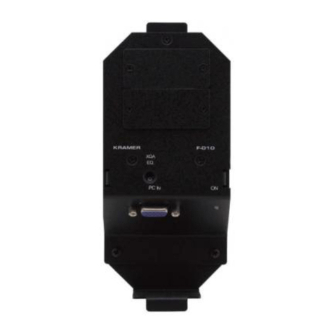
Kramer F-021 User manual

Kramer Electronics, Ltd.
USER MANUAL
Model:
F-021
XGA / Audio Line Amplifier Mounting Box for
Ackermann Floor Boxes

Contents
i
Contents
1Introduction 1
2Getting Started 1
3Overview 2
3.1 DDC Support 2
3.2 Defining EDID 2
3.3 Achieving the Best Performance 3
4Your F-021 XGA / Audio Line Amplifier Mounting Box 4
5Installing the F-021 XGA / Audio Line Amplifier Mounting Box 5
5.1 Installing a Kramer Insert 5
5.2 Connecting the Rear Side of the F-021 5
5.2.1 Wiring the 18-pin Terminal Block Output Connector 6
5.3 Installing the F-021 inside the Ackermann Floor Box 7
5.4 Connecting the Front Panel Ports 8
6Technical Specifications 10
Figures
Figure 1: F-021 XGA / Audio Line Amplifier Mounting Box 4
Figure 2: Terminal Block Pinout 6
Figure 3: Installing the F-021 XGA / Audio Line Amplifier Mounting Box 7
Figure 4: F-021 Fitted in an Ackermann Floor Box 8
Figure 5: Connecting the F-021 XGA / Audio Line Amplifier Mounting Box 9
Tables
Table 1: F-021 XGA / Audio Line Amplifier Mounting Box Features 4
Table 2: Technical Specifications of the F-021 XGA / Audio Line Amplifier Mounting Box 10

Introduction
1
1 Introduction
Welcome to Kramer Electronics! Since 1981, Kramer Electronics has been
providing a world of unique, creative, and affordable solutions to the vast range
of problems that confront the video, audio, presentation, and broadcasting
professional on a daily basis. In recent years, we have redesigned and upgraded
most of our line, making the best even better! Our 1,000-plus different models
now appear in 11 groups1
Thank you for purchasing the Kramer F-021 XGA / Audio Line Amplifier
Mounting Box for Ackermann floor boxes, which is ideal for board,
conference and training rooms, as well as long distance signal distribution.
that are clearly defined by function.
The F-021 includes two single Kramer inserts2(covered with blank inserts)
and is mounted into Ackermann flush floor service units that accept GB2
and GB3 size boxes3
The package includes the following items:
.
•F-021 XGA / Audio Line Amplifier Mounting Box
•Power adapter (12V DC Input)
•This user manual4
2 Getting Started
We recommend that you:
•Unpack the equipment carefully and save the original box and
packaging materials for possible future shipment
•Review the contents of this user manual
•Use Kramer high-performance high-resolution cables5
1 GROUP 1: Distribution Amplifiers; GROUP 2: Switchers and Matrix Switchers; GROUP 3: Control Systems;
GROUP 4: Format/Standards Converters; GROUP 5: Range Extenders and Repeaters; GROUP 6: Specialty AV Products;
GROUP 7: Scan Converters and Scalers; GROUP 8: Cables and Connectors; GROUP 9: Room Connectivity;
GROUP 10: Accessories and Rack Adapters; GROUP 11: Sierra Products
2 The complete list of Kramer products can be found on our Web site at http://www kramerelectronics com
3 GB2 and GB3 are Ackermann mounting boxes that fit into Ackermann floor boxes
4 Download up-to-date Kramer user manuals from the Internet at http://www kramerelectronics com
5 The complete list of Kramer cables is on our Web site at http://www kramerelectronics com


KRAMER: SIMPLE CREATIVE TECHNOLOGY
Overview
2
3 Overview
The F-021 XGA / Audio Line Amplifier Mounting Box for Ackermann floor
boxes is an XGA / Audio line amplifier for computer graphics video signals
up to UXGA and balanced stereo audio. It includes two adjacent openings
for Kramer inserts: two single Kramer inserts, or one dual Kramer insert.
The F-021 features:
•A resolution of up to UXGA
•A built-in audio amplifier
•An SDA (Serial Data) and SCL (Serial Clock) terminal block connector
to pass the EDID information via pins 12 and 15 respectively, on the
15-pin HD connector
•EQ. control for the XGA output
•Left and right audio level trimmers to adjust the output audio level
•A 12V DC power supply
3.1 DDC Support
When establishing a VGA connection between a PC or laptop and a display
device, a set of parameters known as EDID is exchanged between them, which
is carried over the DDC channel. In some PC graphic cards and laptops, this
information exchange is essential for proper VGA OUT operation.
3.2 Defining EDID
The Extended Display Identification Data (EDID1
) is a data-structure provided
by a display to describe its capabilities to a graphics card (that is connected to
the display’s source). The EDID enables the F-021 to “know” what kind of
monitor is connected to the output. The EDID includes the manufacturer’s
name, product type, timing data supported by the display, display size,
luminance data and (for digital displays only) the pixel mapping data.
1 Defined by a standard published by the Video Electronics Standards Association (VESA)

Overview
3
3.3 Achieving the Best Performance
To achieve the best performance:
•Use only good quality connection cables1
•Avoid interference from neighboring electrical appliances that may
adversely influence signal quality and position your Kramer F-021
away from moisture, excessive sunlight and dust
to avoid interference,
deterioration in signal quality due to poor matching, and elevated noise
levels (often associated with low-quality cables)
1 Available from Kramer Electronics on our Web site at http://www kramerelectronics com
KRAMER: SIMPLE CREATIVE TECHNOLOGY
Your F-021 XGA / Audio Line Amplifier Mounting Box
4
4 Your F-021 XGA / Audio Line Amplifier Mounting Box
Figure and1Table define the F-021:1
Figure 1: F-021 XGA / Audio Line
Amplifier Mounting Box
Table 1: F-021 XGA / Audio Line Amplifier
Mounting Box Features
#
Feature
Function
1 Moun ing Tabs For fitting the F-021 into an
Ackermann floor box
2 Blank Inserts (2) Cover he openings that can
be replaced with Kramer wall
plate inserts (see section 5.1)
3 XGA EQ. Trimmer Adjusts1
4
the cable
compensation equalization
level for the output
PC IN 15-pin HD
Female Connector Connect to the XGA source
5 Slide Screws (2) Release to increase or
decrease the length of the unit;
tighten to fix size
6 Adjustable
Mounting Slide For adjusting he size of the
unit to fit an Ackermann floor
box
7 3.5mm Mini Jack Connect to he audio source
8 ON LED Lights red when receiving
power, lights green when
receiving a signal from a video
source
9 AUDIO LEVEL
(L, R) Adjusts the left and right
output signal levels
separately
10 18-pin Terminal
Block Line Output
Connector2
Connect to the line in
connector on the receiver
(see section 5 2.1)
1 Insert a screwdriver into the hole and carefully rotate it, to trim the level
2 Located inside the mounting box

Installing the F-021 XGA / Audio Line Amplifier Mounting Box
5
5 Installing the F-021 XGA / Audio Line Amplifier Mounting
Box
To install the F-021 do the following:
•Install the Kramer inserts (see section 5.1)
•Connect the cables to the rear side (see section 5.2)
•Install the F-021 inside the Ackermann floor box (see section 5.3)
•Connect the front panel ports (see section 5.4)
5.1 Installing a Kramer Insert
To install a Kramer insert, do the following:
1. Unscrew the two screws holding the blank insert and remove it.
2. Place and align the required wall plate insert item over the opening.
3. Insert the two screws to fix the insert in place, and tighten them.
5.2 Connecting the Rear Side of the F-021
To connect the rear side cables, do the following:
1. Run the cables through the Ackermann under floor cable opening.
2. Connect the cables to the rear side of the inserts.
3. Connect the cables1to the rear side of the F-021 (see section 5.2.1), that
is, attach the:
RGBHV terminal block output to the RGBHV acceptor (for
example, a display)
SDA and SCL terminal block connector to pins 12 and 15 of the XGA
output connector
Left and right balanced stereo audio terminal block connectors to
the audio acceptor (for example, active speakers)
4. Connect the 12V DC power supply to the power terminal block
(connect the wire labeled “+” to the +12V pin, and the wire labeled “–”
to the GND pin) taking care that the polarity is correct (see Figure 2).
1 We recommend that you use Kramer C-GM/XL cable, which has a molded male 15-pin HD connector installed on one end,
and the corresponding RGBHV coaxes exposed, pre-stripped and tinned at the other end, as well as two additional wires to
connect pins 12 and 15 for EDID support for details, see our Web site at http://www kramerelectronics com
KRAMER: SIMPLE CREATIVE TECHNOLOGY
Installing the F-021 XGA / Audio Line Amplifier Mounting Box
6
5.2.1 Wiring the 18-pin Terminal Block Output Connector
The 18-pin terminal block is an easy plug-in connector for attaching the
outputs. Follow the colors of the color-coded sticker on these terminals for
proper connection of the UTP cable. Figure 2defines the pinout for the
terminal block.
GND
12V
Audio
Video
EDID
Power
Figure 2: Terminal Block Pinout
Note:
•Use the connector clips only when removing wires, not when inserting
them
•Each wire should protrude 9mm (0.35") from the plastic insulation so
that it can be easily connected. Be sure to fully insert each wire to
prevent them from crossing

Installing the F-021 XGA / Audio Line Amplifier Mounting Box
7
5.3 Installing the F-021 inside the Ackermann Floor Box
To install the F-021 inside the Ackermann floor box, as illustrated in
Figure 3, perform the following steps:
Step 1. Loosen the two slide screws (without removing them) so that the
adjustable mounting slide will move freely.
Step 2. Fit the F-021 mounting box into its designated place inside the
Ackermann floor box (see Figure 4).
Step 3. Insert the fixed tab into the slot in the Ackermann box.
Step 4. Adjust the size of the unit to fit the space in the box.
Step 5. Insert the tab on the adjustable mounting box to the appropriate
slot in the Ackermann box.
Step 6. Tighten the slide screws to fix the size of the unit.
Step 6
Step 5
Step 4
Step 3
Step 1
Figure 3: Installing the F-021 XGA / Audio Line Amplifier Mounting Box

KRAMER: SIMPLE CREATIVE TECHNOLOGY
Installing the F-021 XGA / Audio Line Amplifier Mounting Box
8
Figure 4shows the F-021 fitted in an Ackermann floor box:
Figure 4: F-021 Fitted in an Ackermann Floor Box
5.4 Connecting the Front Panel Ports
To connect the front panel ports do the following:
1. Connect the XGA source (for example, a laptop) to the PC IN 15-pin
HD (F) connector.
2. Connect an audio source to the AUDIO IN 3.5mm mini jack, for
example, using a Kramer C-GMA/GMA cable (VGA 15-pin HD (M)
+Audio jack to VGA 15-pin HD (M) +Audio jack)1,2
1 Not supplied The complete list of Kramer cables is on our Web site at
.
http://www kramerelectronics com
2 Alternatively, you can connect an XGA source to the XGA INPUT 15-pin HD (F) connector, and a separate audio source to
the AUDIO IN 3 5mm mini jack

KRAMER: SIMPLE CREATIVE TECHNOLOGY
Technical Specifications
10
6 Technical Specifications
Table 2lists the technical specifications:
Table 2: Technical Specifications1
INPUTS:
of the F-021 XGA / Audio Line Amplifier Mounting Box
1 UXGA on a 15-pin HD (F) connector
1 Unbalanced stereo audio on a 3.5mm mini connector
1 Power 12V DC on a 2-pin terminal block connector
OUTPUTS: 1 RGBHV for XGA on an 8-pin terminal block connector
SCL and SDA for EDID on a 2-pin terminal block connector
1 Balanced stereo audio on a 5-pin terminal block connector
MAX. OUTPUT LEVEL: Video: 1.7Vpp Audio: ±8.4Vpp
RESOLUTION: Up to UXGA
AUDIO BANDWIDTH: Video: 400MHz Audio >30kHz
DIFF. GAIN: 0.1%
DIFF. PHASE: 0.1 Deg
K-FACTOR: <0.05%
S/N RATIO: Video: 69dB @5MHz Audio: 88dB
CROSSTALK: Audio: 64.5dB from video
CONTROLS: XGA EQ.: 0dB to 8dB; audio level: -74dB to 12dB; power LED
COUPLING: Video: DC Audio: IN = AC, OUT = DC
AUDIO THD + NOISE: 0.004%
AUDIO 2
nd
HARMONIC: 0.0002%
POWER SOURCE: 12V DC 70mA
D MENSIONS: Closed: 7.5cm x 15.7cm x 4.4cm (295” x 6.18" x 1.73") W, D, H
Open: 7.5cm x 20.7cm x 4.4cm (2.95” x 8.15" x 1.73") W, D, H
WEIGHT: 0.19kg (0.42lbs) approx.
ACCESSORIES: Power supply
1 Specifications are subject to change without notice

11
LIMITED WARRANTY
WHOISPROTECTED?
WHATISCOVEREDANDWHATISNOTCOVERED
WHAT WE WILL PAYFOR AND WHATWE WILLNOT PAYFOR
HOW YOU CAN GET WARRANTY SERVICE
LIMITATIONOFIMPLIEDWARRANTIES
EXCLUSIONOFDAMAGES
CAUTION!
We warrantthisproductfreefromdefectsinmaterialand workmanshipunderthefollowingterms
HOWLONGISTHE WARRANTY
Labor and parts are warranted for seven years from the date of the first customer purchase
Only the first purchase customer may enforce this warranty
Wewillpaylaborandmaterialexpensesforcovereditems Wewillnotpayforthefollowing:
Theliability of Kramer for any effective products is limited tothe repair or replacement of theproduct at our option Kramer shall
notbeliablefor:
Thiswarrantygivesyou specificlegal rights,andyoumayalsohaveotherrights,whichvaryfromplace toplace
AllproductsreturnedtoKramerfor servicemusthavepriorapproval Thismaybeobtainedfromyourdealer
Thisequipmenthasbeentestedtodeterminecompliancewiththerequirementsof:
EN-50081: "Electromagneticcompatibility(EMC);
genericemissionstandard
Residential,commercialand lightindustry"
EN-50082: "Electromagneticcompatibility(EMC)genericimmunitystandard
Part1:Residential,commercialandlightindustryenvironment"
CFR-47: FCC* Rules and Regulations:
Part 15: “Radio frequency devices
Subpart B Unintentional radiators”
Except as below, this warranty covers all defects in material or workmanship in this product The following are not covered
bythewarranty:
1 Any product which is not distributed by us or which isnot purchasedfromanauthorized Kramer dealer Ifyou are uncertain as
to whethera dealer isauthorized, pleasecontact Kramerat oneof the agentslisted intheWebsitewww kramerelectronics com
2 Any product, on which the serial number has been defaced, modified or removed, or on which the WARRANTY VOID
TAMPERED sticker has been torn,
3 Damage,deteriorationormalfunctionresultingfrom:
i) Accident,misuse,abuse,neglect,fire,water,lightningorotheractsofnature
ii) Productmodification,orfailuretofollowinstructionssupplied withtheproduct
iii) RepairorattemptedrepairbyanyonenotauthorizedbyKramer
iv) Anyshipmentoftheproduct(claimsmustbepresentedtothecarrier)
v) Removalorinstallationoftheproduct
vi) Anyothercause,whichdoesnotrelatetoaproductdefect
vii)Cartons,equipmentenclosures,cablesoraccessoriesusedinconjunctionwith theproduct
1 Removalorinstallationscharges
2 Costs of initial technical adjustments (set-up), including adjustment of user controls or programming These costs are the
responsibilityoftheKramerdealerfromwhomtheproductwaspurchased
3 Shippingcharges
1 To obtain service on you product, you must take or ship it prepaid to any authorized Kramer service center
2 Whenever warranty service is required, the original dated invoice (or a copy) must be presented as proof of warranty
coverage, and should be included in any shipment of the product Please also include in any mailing a contact name,
company, address, and a description of the problem(s)
3 For the name of the nearest Kramer authorized service center, consult your authorized dealer
All implied warranties, including warranties ofmerchantability and fitness for a particular purpose, are limited in duration to
the length of this warranty
1 Damagetootherpropertycausedbydefectsinthisproduct,damagesbaseduponinconvenience,lossofuseoftheproduct,loss
oftime,commercialloss; or:
2 Anyother damages, whetherincidental, consequential or otherwise Some countries may not allow limitationsonhow long an
implied warranty lasts and/or do not allow theexclusion or limitation of incidental or consequential damages, so the above
limitationsandexclusionsmaynotapplytoyou
Servicing the machines can only be done by an authorized Kramer technician Any user who makes changes or
modifications to the unit without the expressed approval of the manufacturer will void user authority to operate the
equipment
Pleaseuserecommendedinterconnectioncablestoconnectthemachinetoothercomponents
IF reattached, removed or otherwise interfered with
*FCCandCEapprovedusingSTPcable(fortwistedpairproducts)
NOTE:
Part1:

Kramer Electronics, Ltd.
Web site: www kramerelectronics.com
E-mail: info@kramerel.com
P/N: 2900-000745 REV 1
For the latest information on our products and a list of Kramer
distributors, visit our Web site: www.kramerelectronics.com
where updates to this user manual may be found.
We welcome your questions, comments and feedback.
Caution
Safety Warning:
Disconnect the unit from the power supply before
opening/servicing.
Table of contents
Other Kramer Amplifier manuals

Kramer
Kramer VM-4HDT User manual

Kramer
Kramer VM-3H2 User manual

Kramer
Kramer VP-108 User manual

Kramer
Kramer 903 User manual

Kramer
Kramer 901 User manual

Kramer
Kramer VM-5HDxl User manual

Kramer
Kramer TP-202 User manual

Kramer
Kramer VM-22HD User manual

Kramer
Kramer VM-10HD I Series User manual

Kramer
Kramer VM-51 User manual

Kramer
Kramer VM-24H User manual

Kramer
Kramer F-010 User manual

Kramer
Kramer 104LN User manual

Kramer
Kramer VM-114H2C User manual

Kramer
Kramer VM-4HDCP User manual

Kramer
Kramer PA-50HZ User manual

Kramer
Kramer VM-25 User manual

Kramer
Kramer 104LN User manual

Kramer
Kramer VM-2DVI User manual

Kramer
Kramer VM-4HD User manual