Kramer KDS-7-MNGR User manual

Kramer Electronics Ltd.
KDS-7-MNGR –Contents
i
Contents
Introduction 1
Getting Started 1
Overview 2
Typical Applications 3
Controlling your KDS-7-MNGR 3
Defining KDS-7-MNGR 4
Mounting KDS-7-MNGR 5
Connecting KDS-7-MNGR 6
Understanding LED Functionality 7
Operating KDS-7-MNGR 8
Configuring the Network Switch 8
Using Menu Navigation Buttons 8
Operating via Ethernet 9
Using KDS-7-MNGR Embedded Web Pages 14
Defining AV Routing Parameters 16
Routing the Signals 17
Managing the Devices 32
Defining Manager Settings 44
Managing Device Status 60
Viewing the About Page 62
Technical Specifications 63
KDS-7-MNGR Specifications 63
Default Communication Parameters 64
Embedded Web Page Default Values 64
Protocol 3000 65
Understanding Protocol 3000 65
Protocol 3000 Commands 66
Result and Error Codes 72

Kramer Electronics Ltd.
KDS-7-MNGR –Introduction
1
Introduction
Welcome to Kramer Electronics! Since 1981, Kramer Electronics has been providing a world
of unique, creative, and affordable solutions to the vast range of problems that confront the
video, audio, presentation, and broadcasting professional on a daily basis. In recent years, we
have redesigned and upgraded most of our line, making the best even better!
Getting Started
We recommend that you:
•Unpack the equipment carefully and save the original box and packaging materials for
possible future shipment.
•Review the contents of this user manual.
Go to www.kramerav.com/downloads/KDS-7-MNGR to check for up-to-date user manuals,
application programs, and to check if firmware upgrades are available (where appropriate).
Achieving Best Performance
•Use only good quality connection cables (we recommend Kramer high-performance,
high-resolution cables) to avoid interference, deterioration in signal quality due to poor
matching, and elevated noise levels (often associated with low quality cables).
•Do not secure the cables in tight bundles or roll the slack into tight coils.
•Avoid interference from neighboring electrical appliances that may adversely influence
signal quality.
•Position your Kramer KDS-7-MNGR away from moisture, excessive sunlight and dust.
Safety Instructions
Caution:
•This equipment is to be used only inside a building. It may only be connected to other
equipment that is installed inside a building.
•For products with relay terminals and GPI\O ports, please refer to the permitted rating
for an external connection, located next to the terminal or in the User Manual.
•There are no operator serviceable parts inside the unit.
Warning:
•Use only the power cord that is supplied with the unit.
•To ensure continuous risk protection, replace fuses only according to the rating
specified on the product label which is located on the bottom of the unit.

Kramer Electronics Ltd.
KDS-7-MNGR –Introduction
2
Recycling Kramer Products
The Waste Electrical and Electronic Equipment (WEEE) Directive 2002/96/EC aims to reduce
the amount of WEEE sent for disposal to landfill or incineration by requiring it to be collected
and recycled. To comply with the WEEE Directive, Kramer Electronics has made
arrangements with the European Advanced Recycling Network (EARN) and will cover any
costs of treatment, recycling and recovery of waste Kramer Electronics branded equipment on
arrival at the EARN facility. For details of Kramer’s recycling arrangements in your particular
country go to our recycling pages at www.kramerav.com/il/quality/environment.
Overview
Congratulations on purchasing your Kramer KDS-7-MNGR 4K AVoIP Manager. KDS-7-
MNGR is the solution for configuration and management of KDS−7 deployments within the
same network. Simply install the unit into the same local network as the extenders (encoders
and decoders) to easily define and configure channel routing selections (including video,
audio, and a variety of control interface types) using the embedded web pages.
Additionally, this unit supports controlling and configuring the matrix, video wall, and KVM
modes of connected KDS−7 devices as well as device grouping and group operations.
The settings of all connected encoder/decoder units, including IP configuration, compatibility
settings, and extender status are clearly displayed and easily updated.
KDS-7-MNGR provides outstanding end-user experience, robust security, and is ideal for
large-scale deployment and operation.
Outstanding End-user Experience
•Instant Auto−discovery and status with preview.
•Access via remote Web UI or by using a local monitor with a USB keyboard and mouse.
Robust Security
•Enterprise IT-grade security − 802.1x and HTTPS/TLS.
•Security certification − OWASP Top 10 certificate.
•Can be deployed in the same LAN used for AV data streaming or in a separate LAN.
Efficient Large-Scale Deployment and Operation
•Highly scalable –manages up to 999 channels.
•Configuration of virtual video matrix, KVM, and video walls.
•Configuration of Device Grouping, Preset Definition, and Activation via UI or APIs.
•FW configuration –For a single device or a group of devices.
•Simple Planning and Rollout –Cost-effective from day one.
•Full product range for any site and any application.

Kramer Electronics Ltd.
KDS-7-MNGR –Introduction
3
Advanced and User-friendly Operation
•Convenient and Comprehensive Control –Control the unit using intuitive embedded web
pages, Protocol 3000 API commands via Ethernet, or front panel LCD and navigation
buttons.
•PoE Support –Powered with PoE connection from PoE switch.
•Keyboard and Mouse Roaming.
•Control Gateway - Through P3K or special TCP connection, users can
control/communicate with IR, RS-232, or CEC to the connected devices.
Typical Applications
KDS-7-MNGR is ideal for the following typical applications:
•Real-time essential installations such as command and control rooms.
•Large scale AV content sharing installations using existing wires and infrastructure in
corporate offices and government applications.
•AV distribution systems with one or more sources and multiple displays in schools,
universities, and public venues.
•AV installations where low latency KM/KVM capabilities are required.
Controlling your KDS-7-MNGR
Control your KDS-7-MNGR directly via Navigation buttons, or via:
•The Ethernet using built-in user-friendly web pages.
•Protocol commands.

Kramer Electronics Ltd.
KDS-7-MNGR –Defining KDS-7-MNGR
4
Defining KDS-7-MNGR
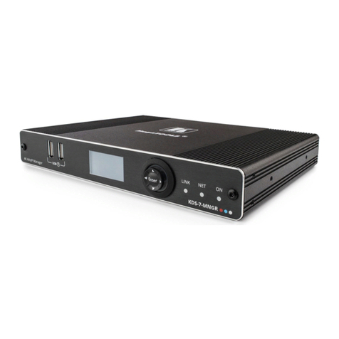
Figure 1: KDS-7-MNGR 4K AVoIP Manager
#
Feature
Function
USB Type A Charging
Ports
Connect to a keyboard and mouse to control the units via UI using a
display connected to the unit via HDMI output port.
LCD Display
Use for device information and configuration.
Menu
Navigation
Button
Press to return to the previous menu.
Press to move up to the next configuration parameter.
Press to go to the next menu.
Press to move down to the next configuration parameter.
Enter
Press to accept changes.
LINK LED
See Understanding LED Functionality on page 7.
NET LED
ON LED
24V/5A DC Connector
Plug the 24V DC power adapter into the unit and connect it to an AC
wall outlet for power. (Optional, not required if the unit is powered via
PoE).
RESET Recessed Button
Press and hold for about 20 seconds, until all LEDs flash, to reset the
device to its factory default values.
LAN Port
Connect directly, or through a network switch, to your PC/ laptop to
control the unit via WebGUI/Telnet.
HDMI OUT Port
Connect to a display to control the unit directly.
1
2
3
4
5
6
7
8
9
10

Kramer Electronics Ltd.
KDS-7-MNGR –Mounting KDS-7-MNGR
5
Mounting KDS-7-MNGR
This section provides instructions for mounting KDS-7-MNGR. Before installing, verify that the
environment is within the recommended range:
•Operation temperature –0to 40C (32 to 104F).
•Storage temperature –-40to +70C (-40 to +158F).
•Humidity –10% to 90%, RHL non-condensing.
Caution:
•Mount KDS-7-MNGR before connecting any cables or power.
Warning:
•Ensure that the environment (e.g., maximum ambient temperature & air flow) is
compatible for the device.
•Avoid uneven mechanical loading.
•Appropriate consideration of equipment nameplate ratings should be used for avoiding
overloading of the circuits.
•Reliable earthing of rack-mounted equipment should be maintained.
•Maximum mounting height for the device is 2 meters.
Mount KDS-7-MNGR in a rack:
•Use the recommended rack adapter
(see www.kramerav.com/product/KDS-7-MNGR).
Mount KDS-7-MNGR on a surface using one of the following
methods:
•Attach the rubber feet and place the unit on a flat surface.
•Fasten 2 brackets (included) on each side of the unit and attach it
to a flat surface. For more information go to
www.kramerav.com/downloads/KDS-7-MNGR.

Kramer Electronics Ltd.
KDS-7-MNGR –Connecting KDS-7-MNGR
6
Connecting KDS-7-MNGR
By-default, the device uses PoE for powering the device. Optionally, you can separately
purchase a power adapter to connect to the product and plug into the mains electricity.
Always switch off the power to each device before connecting it to your KDS-7-MNGR. After
connecting your devices, connect their power and then switch on the power to each device.
Figure 2: Connecting the KDS-7-MNGR
To connect KDS-7-MNGR as illustrated in the example in Figure 2:
1. Connect the LAN RJ-45 port to the LAN switch.
2. Connect the HDMI OUT connector to an HDMI acceptor (for example, a display).
3. Connect a mouse and a keyboard to the two USB type A ports .the USB ports.
9
10
1

Kramer Electronics Ltd.
KDS-7-MNGR –Connecting KDS-7-MNGR
7
Understanding LED Functionality
KDS-7-MNGR LEDs function as follows:
LED
Color
Definition
LINK LED
Lights Green
A link is established between KDS-7-MNGR and the TV and is
transmitting A/V signals.
NET LED
Off
No IP address is acquired.
Lights green
A valid IP address has been acquired.
Flashes Green very fast (for 60sec)
A device identification command is sent (Flag me).
Lights Yellow
Device falls back to default IP address.
Lights Red
Security is blocking IP access.
ON LED
Flashes Red
On fallback address acquiring, device ‘ON’ LED flashes
continuously in slow 0.5/10sec cadence
Lights Green
When power is on.
Flashes Green Slowly
Device is in standby mode.
Flashes green fast
FW is downloaded in the background.
Flashes Green very fast (for 60sec)
A device identification command is sent (Flag me).
Lights Yellow
Device falls back to default IP address.
Lights Red
Security is blocking IP access.
Post reboot, all LEDs light for 3 seconds then return to their normal LED display mode.

Kramer Electronics Ltd.
KDS-7-MNGR –Operating KDS-7-MNGR
8
Operating KDS-7-MNGR
This section describes the following actions:
•Configuring the Network Switch on page 8.
•Using Menu Navigation Buttons on page 8.
•Operating via Ethernet on page 9.
Configuring the Network Switch
Before setting the system, make sure that your AV over IP network switch meets the following
minimum requirements:
•Jumbo Frames –On. (at least 8000 bytes).
•IGMP Snooping –On.
•IGMP Querier –On.
•IGMP Immediate/Fast Leave –On.
•Unregistered Multicast Filtering –On.
Using Menu Navigation Buttons
Connect the device to the 24V DC power adapter and connect the adapter to the mains
electricity. The ON LED lights green, and the LINK LED flashes (indicating that no streaming
activity is detected).
Use the navigation button to easily view and set basic device parameters via the Device
menu, appearing on the device LCD display , see:
•Using KDS-7-MNGR Navigation Buttons on page 9.
Use the Navigation buttons / Use the:
•Down arrow –to move to the previous configuration parameter.
•Up arrow –to move to the next configuration parameter.
•Left arrow –to return to the previous menu.
•Right arrow –to go to the next menu.
•Enter button –accept and save the change.
2
3

Kramer Electronics Ltd.
KDS-7-MNGR –Operating KDS-7-MNGR
9
Using KDS-7-MNGR Navigation Buttons
•Defining Device Status on page 9.
•Viewing Device Information on page 9.
Defining Device Status
View the device parameters.
To view device parameters:
1. Press the Enter or right arrow to access the device status (DEV STATUS) menu.
2. Press the up or down arrows to view the following information:
▪LAN STATUS, including IP address, Subnet mask and Gateway address
▪HDMI STATUS, including video output resolution.
▪Device internal TEMPERATURE (°C).
Device status is viewed.
Viewing Device Information
Displays the device information.
To view device parameters:
1. Press the left or right arrows to access the device status menu.
2. Press the up or down arrows to view the device firmware and hardware information:
▪Firmware version (FW).
▪Bootloader information (BL).
▪Hardware version (HW).
Device information is viewed.
Operating via Ethernet
This section describes the following actions:
•Allocating the IP Address via LCD screen menu on page 10.
•Accessing the Web UI on page 10.
•Connecting Ethernet Port Directly to a PC on page 11.
•Connecting Ethernet Port via a Network Hub or Switch on page 13.
•Configuring Ethernet Port on page 13.

Kramer Electronics Ltd.
KDS-7-MNGR –Operating KDS-7-MNGR
10
Allocating the IP Address via LCD screen menu
KDS-7-MNGR IP default static addresses is: 192.168.1.39 By default, DHCP is enabled, and
assigns an IP address to the device. If DHCP Server is not available, for example, in case a
device is connected directly to the laptop, that device gets the default IP address. If these IP
address is already in use, the system searches for a random unique IP in the range of
192.168.X.Y. the allocated IP address can be identified using the LCD screen menu.
By default, KDS-7-MNGR is DHCP-enabled. This section describes how to operate via the
Ethernet and access the IP address when DHCP is enabled and when a static IP address is
used.
You can connect to KDS-7-MNGR via Ethernet using either of the following methods:
•When DHCP is enabled (see, for example, KDS-7-MNGR Network Settings on page 48).
When using a static IP Address (DHCP is disabled):
•Directly to the PC using a crossover cable (see Connecting Ethernet Port Directly to a
PC on page 11).
•Via a network hub, switch, or router, (using a static IP address) using a straight-through
cable (see Connecting Ethernet Port via a Network Hub on page 13).
If you want to connect via a router and your IT system is based on IPv6, speak to your IT
department for specific installation instructions.
Accessing the Web UI
By default, IP setting is DHCP.
To access the Web UI, perform the following:
1. Connect the LAN port of the device to a local area network.
Make sure that there is a DHCP server in the Network so that the device can obtain a
valid IP address.
2. Connect your PC to the same network as the device.
3. Enter the device’s IP address in the browser and press Enter, the Login window opens.
Figure 3: Login Window
The allocated IP address can be checked using LCD screen menu.

Kramer Electronics Ltd.
KDS-7-MNGR –Operating KDS-7-MNGR
11
4. Input username and password (default username/password: admin/admin) and click
Sign In to enter the main page of web UI.
See Defining User Management on page 57 for defining new users.
Connecting Ethernet Port Directly to a PC
You can connect the Ethernet port of KDS-7-MNGR directly to the Ethernet port on your PC
using a crossover cable with RJ-45 connectors.
This type of connection is recommended for identifying KDS-7-MNGR
with the factory configured default IP address.
After connecting KDS-7-MNGR to the Ethernet port, configure your PC as follows:
1. Click Start > Control Panel > Network and Sharing Center.
2. Click Change Adapter Settings.
3. Highlight the network adapter you want to use to connect to the device and click Change
settings of this connection.
The Local Area Connection Properties window for the selected network adapter appears
as shown in Figure 4.
Figure 4: Local Area Connection Properties Window
4. Highlight either Internet Protocol Version 6 (TCP/IPv6) or Internet Protocol Version 4
(TCP/IPv4) depending on the requirements of your IT system.
5. Click Properties.
The Internet Protocol Properties window relevant to your IT system appears as shown in
Figure 5 or Figure 6.

Kramer Electronics Ltd.
KDS-7-MNGR –Operating KDS-7-MNGR
12
Figure 5: Internet Protocol Version 4 Properties Window
Figure 6: Internet Protocol Version 6 Properties Window
6. Select Use the following IP Address for static IP addressing and fill in the details as
shown in Figure 7.
For TCP/IPv4 you can use any IP address in the range 192.168.1.1 to 192.168.1.255
(excluding 192.168.1.39) that is provided by your IT department.

Kramer Electronics Ltd.
KDS-7-MNGR –Operating KDS-7-MNGR
13
Figure 7: Internet Protocol Properties Window
7. Click OK.
8. Click Close.
Connecting Ethernet Port via a Network Hub or Switch
You can connect the Ethernet port of KDS-7-MNGR to the Ethernet port on a network hub or
using a straight-through cable with RJ-45 connectors.
Configuring Ethernet Port
You can set the Ethernet parameters via the embedded web pages.

Kramer Electronics Ltd.
KDS-7-MNGR –Using KDS-7-MNGR Embedded Web Pages
14
Using KDS-7-MNGR Embedded
Web Pages
KDS-7-MNGR and can be operated remotely using the embedded web pages. The web
pages are accessed using a Web browser and an Ethernet connection.
Before attempting to connect:
•Perform the procedures in Operating via Ethernet on page 9.
•Ensure that your browser is supported.
The following operating systems and Web browsers are supported:
Operating Systems
Browser
Windows 7
Firefox
Chrome
Safari
Windows 10
Edge
Firefox
Chrome
Mac
Safari
iOS
Safari
Android
N/A
Some features might not be supported by some mobile device operating systems.
KDS-7-MNGR enables performing the following:
•Defining AV Routing Parameters on page 16.
•Routing the Signals on page 17.
•Managing the Devices on page 32.
•Defining Manager Settings on page 44.
•Managing Device Status on page 60.
•Viewing the About Page on page 62.
In the following sections, as an example, 2 encoders and 2 decoders are connected to the
system.

Kramer Electronics Ltd.
KDS-7-MNGR –Using KDS-7-MNGR Embedded Web Pages
15
To Browse the KDS-7-MNGR Web Pages:
1. Open your Internet browser.
2. Type the IP number of the device in the Address bar of your browser. For example, the
default IP number:
. The Login window appears.
Figure 8: Login Window
3. Enter the Username and Password (admin/admin, by default).
KDS-7-MNGR page appears (the AV Routing tab in the AV Routing page).
Figure 9: Controller Application Page with Navigation List on Left
4. Click the tabs on the left side of the screen to access the relevant web page.

Kramer Electronics Ltd.
KDS-7-MNGR –Using KDS-7-MNGR Embedded Web Pages
16
Defining AV Routing Parameters
Set the KDS-7-MNGR AV routing parameters.
To set AV routing parameters, as needed:
1. In the Navigation pane, Select Main>AV Routing. The AV Routing page appears (see
Figure 9).
2. Next to Routing View, click Matrix (default) to view the system as a matrix (see
Figure 9) or click Icon to view each encoder/decoder as icons.
3. Click SAVE AS PRESET: to save this setting as a preset.
Figure 10: Saving a Preset
Enter the preset name and then click SAVE.
A/V routing is saved as a preset for KDS-7-MNGR. the Preset tab lists the presets.
Preset name is alphanumeric and can include hyphens ans under scores within the
name.
4. Under Encoder/Decoder Filters, enter the name of an encoder or decoder, to find a
specific device from the device list.
5. Click next to an encoder to watch a preview of the streaming.
Routing parameters are defined.

Kramer Electronics Ltd.
KDS-7-MNGR –Using KDS-7-MNGR Embedded Web Pages
17
Routing the Signals
KDS-7-MNGR enables routing AV signals as well as USB, IR, RS-232 and CEC signals.
When the routing view is set to Icon, all the signals are routed together by dragging and
dropping an encoder icon to a decoder. Only in the Matrix format you can select each signal
separately.
KDS-7-MNGR enables routing and managing the signals as follows:
•Routing Video and Audio Signals on page 17.
•Routing a USB Signal on page 18.
•Routing an IR Signal on page 20.
•Routing an RS-232 Signal on page 22.
•Routing a CEC Signal on page 24.
•Routing to a Video Wall on page 27.
•Managing Presets on page 30.
•Performing a Preset Sequence on page 31.
Routing Video and Audio Signals
To route a signal from an encoder to a decoder:
1. In the Navigation pane, Select Main>AV Routing. The AV Routing page appears (see
Figure 9).
2. Select the Video/Audio signal tab.
3. Check the cross-point between an encoder and decoder to pass both audio and video
from the encoder. Or
Click +to separate the signal to video and audio and check a separate cross-point for
each.
Figure 11: Separating Video and Audio Signals

Kramer Electronics Ltd.
KDS-7-MNGR –Using KDS-7-MNGR Embedded Web Pages
18
4. If required, split the audio and video sources (for example, the E1 decoder streams the
video, and the other decoder streams the audio).
Figure 12: Streaming Audio and Video from Separate Sources
The video and audio signals are routed from the encoder to the decoder.
Routing a USB Signal
To route a USB signal, perform the following actions.
•Configuring KVM Settings on page 18.
•Routing the USB Signal on page 19.
Configuring KVM Settings
Configure each decoder to enable passing a USB signal between encoders and decoders
To configure KVM settings:
1. Access the decoder UI.
2. In the Navigation pane, Select Main>AV Routing. The AV Routing page appears.
Other manuals for KDS-7-MNGR
1
Table of contents
Other Kramer Network Hardware manuals
Popular Network Hardware manuals by other brands

Rohde & Schwarz
Rohde & Schwarz CompactTSVP Getting started

Xyclop
Xyclop XC-4CH-NVR-1TB user manual

Ensemble Designs
Ensemble Designs Avenue Intersection Frame Data Pack

Multitech
Multitech MultiConnect eCell user guide

HIK VISION
HIK VISION DS-96000NI-I16 Series quick start guide

HIK VISION
HIK VISION NVST HNR Series user manual

HIK VISION
HIK VISION DS-9608NI-I8 quick start guide

DVR SYSTEMS
DVR SYSTEMS Network Video Recorder user manual

Hamilton/Buhl
Hamilton/Buhl SNIPS SNIP18 instruction manual

HIK VISION
HIK VISION Ds-7604ni-e1, ds-7608ni-e1 user manual

SimCom
SimCom SIM7022-EVB user guide

HIK VISION
HIK VISION HWN-2104H-4P user manual