Krell Industries MD-10 Quick start guide

MD-10 OWNER’S REFERENCE

A. INTRODUCTION
TCrOngratulationson your purchase of the MD-10CD
anscription turntable and welcometo the KRELL
family oFaudio components.Youha.vejoined a select
groupof listeners whoenjoyonly tlae tlnest in music
reproduction.
Weare dedicatedto the~ developmentof technologically
advancedcomponentstor the reproduction o.f digat~ly
recordedmusicandcontinuingthe Krell tradition ot
uncompromisedperformancethrough leading-edge tech-
nology.
This Owner’sReferenceis divided into several sections,
eachdesignedto performa different function. Basic
installation, operation and a Questionand Answersection
are included, whereanswersto commonquestions are
provided. Shouldyouhave any questions or suggestigns,
i~leasefeel free to contactyourauthorizeddealeror tlae
KRELLstaff for assistance.
In the unlikely, event that your.MD-1.0shouldrequire
serviceyouwill bepleased~to l~n~owtlaat it is backedbya
c.omprehensiveCustomerbatistaction policy and one of
tlae mostadvancedservicefacilities in the industry, bor
detailed informationon the termsandconditions of ser-
vice pleaseconsult yourwarra..ntyregistration card or
your authorized KRELLDistributor.
2

B. TABLE OF CONTENTS
3
4
6
9
11
12
15
16
18
19
UNPACKING AND ASSEMBLY
DUST COVER INSTALLATION
BASIC INSTALLATION AND CONNECTIONS
OPERATION OF THE CD TRANSPORT
REMOTE CONTROL
TRACK AND FTS PROGRAMMING
MAINTENANCE
QUESTIONS AND ANSWERS
SPECIFICATIONS
WARRANTYAND SERVICE INFORMATION
C. UNPACKING AND ASSEMBLY
1. Openthe boxandremovethe top layer of protective
foam.Thefollowing items will nowbe visible:
1 DustCoverencasedin a protective sleeve
1 CDStabilizer
1 ACpower cord
1 MD-10RCRemoteControl
1 Packet containing the Owner’sReferenceand warranty
card
NOTE:If any of these items are not included, please
contact yourauthorizeddealer immediatelyfor assis-
tance.
2. Removethe layer of foamcontaining these items and
set it aside for later use. Carefullyremovethe MD-10
fromits boxand removethe protective plastic wrap.
NOTE:Saveall packingmate.rials. If youmustship your
MD-10in the future, repackthe unit in its original pa,ck-
agingto preventtransit damage.If the unit is re.turnedto
KRELLfor service, please send the cover and tlae remote
controlunit.
CAUTION:Donot removethe acrylic dust cover from its
protective sleeveat this time! Thiscoveris extremely
~lelicate andca.n be permanentlyscarred if mishandled.
Pleasefollowtlae instructions providedin this Reference
for safeinstallation. 3

D. DUST COVERINSTALLATION
1. Lookingat the front of the MD-10,locate the two
black hinge block assemblies on the rear left and right
corners. (Refer to location diagram)
2. Locate the hinge pin on the back of each hinge block
assemblyand pull themout gently until they are fully
extended.
t3h. Openthe flap only on the protective sleeve and locate
e three cover pins.
4. Place the cover over the unit and insert the cover into
the hinge block assemblies with the cover in the ~
u~ri~ht~osition. Makesure all three pins are in there
proper receptacles. Refer to location diagram on page 5.
5. Lockthe cover into the hinge blocks .by pushing the
pins into themuntil they are fully seated.
6. Gently pull the cover forward and let it go, allowing
the cover to slowly descend.
CAUTION:Do not push the dust cover down. Its damp-
ing system allows a slow descent, and can be damagedif
force is applied.
7. Removethe protective sleeve.
4

1 Dust cover
2 Hinge block
3 Adjustable suspension tower
4 Transport
5 Hinge pin
6 Cover pin
7 Bubblelevel
MD-10 LOCATION DIAGRAM
5

E. BASIC INSTALLATIONAND
CONNECTIONS
1. Place the unit on a clean, level surface awayfrom
excessiveheat, moist.ure or light. Ideally, the MD-10
shouldbe placedon tlae top of an audiocomponentcat)i-
net or other "openair" rigid platform.
2. TheMD-10may.be. placedin a cabinet. It will require.
17.0 inchesof vertical clearance betweenthe bottomanti
top shelves for properoperationof the cover.
3. If. spaceis limited, the MD-10can be operatedwithout
its clust cover.Sixinchesvertical clearanceis adequateto
allowconvenientaccess to the disc transport area.
4. Thelocation of the unit shouldbe within 2 metersof
the digital signal proeess0r~If longerdistanc.eis re_quired,
werecommendusing an AT&Tfi.~re optic clata linl~ o.r an
AES/EBUbalanced~lata.link, as tlaey are moresuitecl to
long distance runs. --~
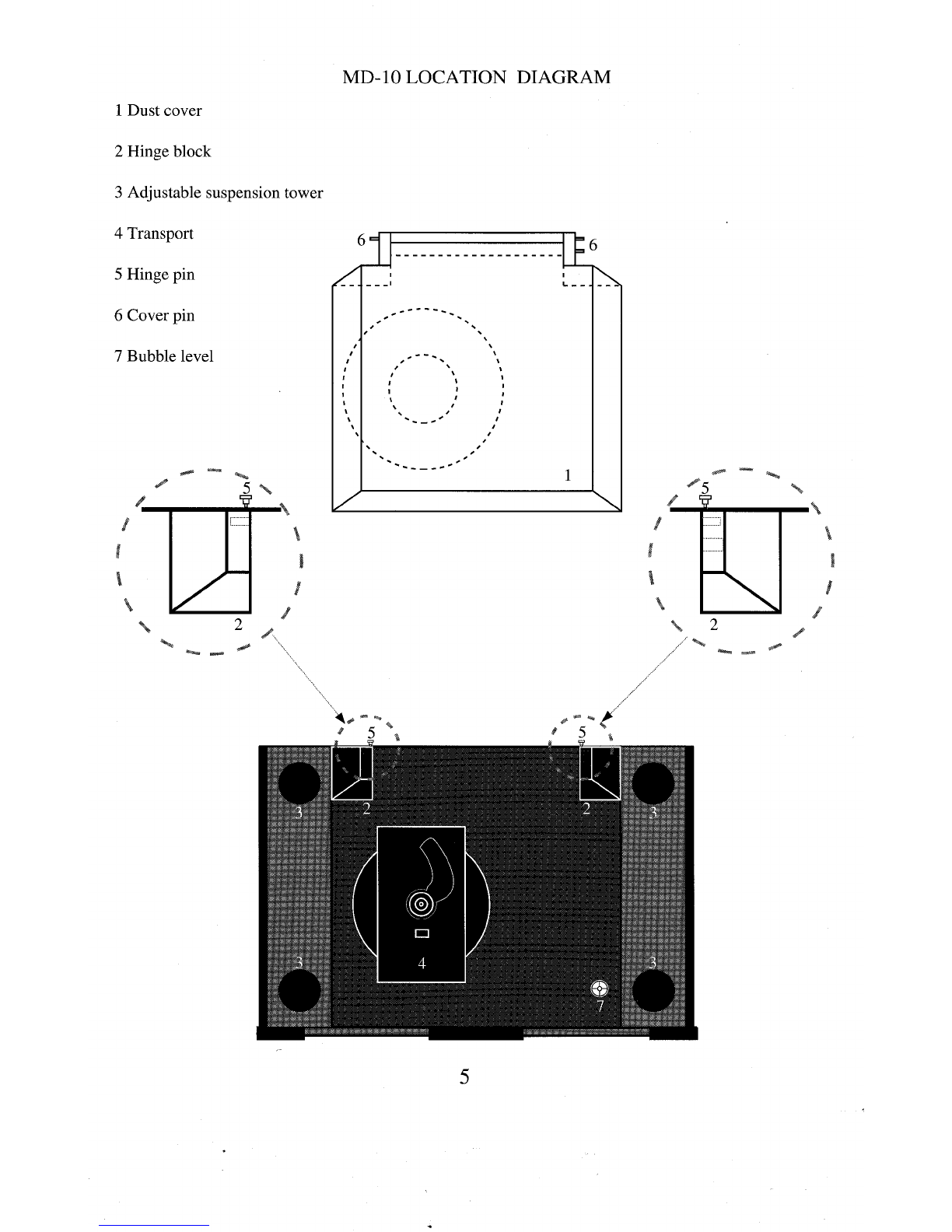
5. Onceyouhavefounda location for the unit, adjust the
transport’s a_djustable suspensiontowersto makethe
MD--10ssurffice level. Abubblelevel is conveniently
mountedin the blackacrylic, tOl~plate, allowingfor easy
level adjus.t.ment,Adjusteacla ot the four suspension
towersuntil the bublSlein the level is centered.Counter
clockwiserotation raises the towersand clockwiserota-
tion lowersthe towers.
NOTE:Theadjusta.ble suspension towers are only for
fine a.djustmentanti can not compensatefor gross surface
irregularities.
6. Connectthe ACpowercord to the backof the unit.
Oncethe powercord is secured, plug the cord into an AC
outlet.
7. Press the POWERbutton on the front panel. Thedis-
play will illuminate andthe transport will nowbe active.
NOTE:While the MD-10has superb regulation and does
not require a dedicatedACcircuit, westrongly advise
against any. connectionsthroughextension cords or mul-
tiple ACa~laptors. Highquality 15 ampgroundedAC
strips are acceptable.
6

8. Connectthe Digital Outputfromthe MD-10to a Krell
Digital Processoror other compatibledigital-to-analog
audioprocessor.
TheMD-10is compatible with industry standard Fibre
~O_[?tic, Coaxial RCA,AT&TwidebandwidthFibre Optic
~1 type and AES/EBUXLRoutput connectors.
NOTE:Care should be taken in selecting the type of
cable used to lin.k the MD,10to yourprocessor. We
recommendbotla the AT&TFibre Optic due to its supe-
rior bandwidthandsignal isolation properties, andttie
AES/EBUformat due to its higher voltage transmission
andnoise rejection dueto balancedformat.
CAUTION:The MD-10is a CDTransport only. It is not
designedto connectdirectly to any preampor analog
signal processor.
TheMD-10is equippedwith a sp.ecial terminatiop sys-
temcalled TimeSync.TimeSyncis a systemthat locks.
the clock betweenthe MD-10and specific Krell digital-
to-analog processors. This connectionis labeled
SPECIALon the back of the MD-10.Thetermination is
via an AT&Tfibre optic cable only and is usedin con-
junction with anyof-the other digital links like the AT&T
or AES/EBU.
NOTE:The TimeSyncsystem can ~ be utilized with
certain Krell digitaI-to-analog convertersandwill not
workwith any other makeor model.Please consult your
dealer or the Krell staff for specific information.
NOTE:TheTimeSyncoutput can not be used as an addi-
tional digital output.
TIMESYNC CONNECTION
The TimeSyncsystem is terminated via an AT&TST
fibre optic cable.
1. Connectthe AT&Tfibre optic cable to the termination
labeled SPECIALon the MD-10.Makesure the small
keyat the top of the fibre optic cableis uprightandfits
smoothlyinto the AT&Treceptacle, twist the collar
clockwiseto lock the cable in place.
2. Connectthe free endof the fibre optic cableto the
termination labeled TimeSync/Extclock on the back of
yourKrell digital-to-analog converter.
7

3. Connectyour digital interlink betweenthe transport ,
anddigital-to-analog converter, if not already connectecl.
4. Select a digital source and press the TimeSyncbutton
on the front of your digital-to- analo~ converter. The
corresponding led will-illuminate indicating the
TimeS-yncis locked. Should the TimeSync-LEDflash,
tlais meansthe TimeSyncclock has not locked and. re-
quires, resetting. Select anyother digital input.on tlae
digital-to-analog converter and then reselect the input,
you. wisla to use. The TimeSyncLEDwill nowbe steacly
and the clock will be locked.

F. OPERATIONOF THE CD
TRANSPORT
1. Turnthe CDtransport ONby pressing the Power
b.utton., Thedisplaywill illuminate. Selecta disc an.d
placeit onthespindl~e,label sideup. Putthe discst.alfi-
fizer onthe centerot the CDso it fits securelyontide
drive spindle.
CAUTIONS:Never operate the CDtransport without the
disc stabilizer. Thiscanresult in damageto the transport
or your valuable compactdiscs.
b. Neverplace the disc stabilizer wherethe covermay
accidentally close on it anddamagethe cover.
c. Donot use anydisc stabilizing tool besidesthe Krell
CDStabilizer. Th.is devicehas beenspecially machin.ed
to preciselymatclathe CDtransport. Failure to heedtlais
warningmaycause damageto the laser transport.
2. Thefunctionsof the front panelbuttons that control
the transport are describedbelow.
POWER
STOP
PLAY
PAUSE
TRACK I<
TRACK >1
INDEXI<
INDEX>1
SEARCHI<
SEARCH>l
FTS
PROGRAM
REPEAT
Turns unit ONor OFF
Stops the disc fromplaying
Starts the discplayingat. track1;
willalsorestart playof tlae
current track
Tem.porarilystops play of current
track
Reversetrack select
Forwardtrack select
Reverseindex select
Forwardindex select
Fast reverse search
Fast forwardsearch
ProgramsFTSmemory;will also play
FTS-encodeddiscs
Stores selected tracks in memory
Starts play fromthe beginningonce
disc has finished
9

3. Select a track on the CDto play with the remotecon-
trol or via the front panelandpress the Playbutton. The
musicwill nowbegan.
10

G. REMOTE CONTROL
1. Theoperatingfunctionsof the RemoteControlare
describei] below:
POWER
STOP
PLAY
PAUSE
TRACKI<
TRACK>1
INDEXI<
INDEX>l
SEARCHI<
SEARCH>l
FTS
PROGRAM
RPT
Turns unit ONor OFF
Stops the disc fromplaying
Starts the disc playingat. track1;
will alsorestart prayof the
current track
Tem.porarilystops play of current
track
Reversetrack select
Forwardtrack select
Reverseindex select
Forwardindex select
Fast reverse search
Fast forwardsearch
ProgramsFTSmemory;will also play
FTSencodeddiscs
Stores selected tracks in memory
Starts play fromthe beginningonce
disc has finished
2. TheMD-10remotecontrol has a 10.d_i.git keypad.The
keypadallowsfor direct accessto specific tracks. Pu,nch
in tlae [rack numberyouwantandpress Play, tlae track
youselected w_ill beginplaying. Thedirect access keypad
IS convenient tor track and FTSprogramming.
11

H. TRACK PROGRAMMING
The remote control or the front panel of the MD-10can
be used to programspecific tracks on a disc to be played
in the order you choose. The MD-10can store up to 20
selections per program.
1. Select the track numberwhichwill start the sequence
into the keypad, then push the PROGRAMor PROGR
button. A’~" will appear next to the track number.
2. Enter the rest of the track selections in. your programin
the same manner remembering, to push the program
button after each track selected.
3. Onceyou have finished your program.m,ing: push the
PROGRAMor PROGRbutton again ending the program
sequence. The machinewill then review the tracl~s you
have selected.
4. Press the PLAYbutton and the programwill begin.
Whilethe.progr.am is running you can Pause, Search. and
select tracks within the prog_ram.Youcan start a track
playing from the beginning by pressing the Play button.
P.ress STOPonly to ~tefeat, or erase, ttie programfunc-
tion.
5. Press. the .REPE.ATbutton and the machinewill play
your selected tracks over again in the sameorder tlaey
were programmed.
6. To cancel your program push the STOPbutton.
FTS MEMORY
FTS,or Favorite Track Selection, is a feature that enables
youto store desired tracks on a CD,in a sp~ecific order,
into the memoryof the MD-10. Onceyou have pro.-
grammeda disc with FTS, the machine will give that
specific CDa reference number. The machine remembers
.tfiis information and will play the tracks you havese-
lected for that CDwith a simple command.The machine
can also play the entire disc should you choose.
12

FTS PROGRAMMING
Toprogramtracks in the FTSmemory:
NOTE:Before you begin,place disc to be progra.mmed
on the unit andpress PLAY.Oncethe unit reacls the table
of contentsanddisplays the disc’s playing_time,press
STOEYoucan nowbegin programming the FTS
memory.
1. Programthe selections in the standard formdescribed
above.
~
. After youhaveprogra.mmedthe tracks, press the FTS
utton on the front panel or onthe remotecontrol. The
FTSindicator in the display will flash.
b3. Whilethe indicator is flashing, press the PROGR.AM
utton. Themachinewill then display a numberon the
screen briefly. This is the FTSdesignation number.When
this numberappears the FTSprogrammingis complete.
N.O.TE:Youmaywant to label.the disc youprogrammed
with the FTSdesignation numberso it can easiIy be
erased or changed-inthe future.
4. Youcan nowstart playing your FTSprogrammeddisc.
TO PLAYAN FTS DISC
1. Press the FTSbutton on the remoteor front panel
before you press PLAY.
2. TheFTSindicator on the display will flash.
3. Whileit is flashing, press the PLAYbutton andthe
.MD-10wi.ll play_only the tracks in FTSmemo.ry.If you
clo not wishto play.onlythe FTSselectedtracks o~n.a
disc, press Playwithout pressingthe FTSbuttonfirst.
Theentire disc will nowplay.
13

TO ERASE FTS PROGRAM MEMORY
NOTE:FTSmemorycan only be erased via the front
panel controls. Theremote control cannot erase FTS
memory.
NOTE:The disc does not have to be on the MD-10to
~
rase FTSmemory. Erasure can be completed with no
isc on the drive spindle.
~
. Press the FTSbutton on the front panel. Holdthe .
u.tton in while pressingthe forward or backwardtrack
select. Youwill notice t-he machineis scrolling through
F.TS designation.numbers. Once you have found the FTS
.designatio.n numt)er you wantto erase, press the STOP
button and the programwill be erased.
14

I. MAINTENANCE
.B.e.causeof its superbbuild quality the MD-10requires
little maintenance.Shouldtlie unit becomeexcesslvly
dirty, clean the lens assemblywith a cameralens brush
madeof a soft material like camelhair. Theacrylic top
p!ate anddust covershouldbe cleanedwith the poli~stiing
.kit provided.Readthe directions onthe containers tor
best polishingresults.
REMOTECONTROLBATTERYINSTALLATION
AND REMOVAL
Thebatteries in the remotecontrol should be changed
whenthe tran.sport is nolongerun.derstaqding.or cor-
rectly respondingto the commanOssent tromtlae unit.
R~e.movethe four socketcapscrewsfromthe backportion
ot tlae remotecontrol. Removethe backplate to expose
the battery storage compartment.Referto the polarity
drawing.w,hile inserting the batteries. Replacethe back
plate andinsert the four socketcapscrews.
FUSE INSTALLATION AND REMOVAL
If the MD-10does not seemto power-up,unplugthe unit
fromthe ACwall socket and checkthe fuse.
1. Locatethe fuse holderon the backof the unit labled
FUSE.Turnthe fuse holder counter clockwise and gently
pull the fuse free fromthe chassis.
2. Checkto makesure the foil in the center of the fuse is
still connected.If youare still unsure,measurethe fuse
with an ohmmeterto determineif it is intact. TheMD-10
uses a 1 ampfast-blow fuse at l15v anda .5 ampfast-
blowfuse at 220v. Shouldthe fuse needreplacing, use
onlythe fuse specified.
3. Placethe fuse into .the receptacleandpushandtu.m
gentlyclockwiseuntil the fuse holderis .~ully seated.
Plugthe unit into the ACwall socket and press the Power
button.
CAUTION:Should the MD-10n.ot powe~r-upand
con.tinouslyblowfuses, unplugthe unit tro.m, the ACwall
outlet andcontactyourKre-ll dealer or distributor.
15

J. OUESTIONS AND ANSWERS
Q. MyDigital to Analog ~processor will accommodate
either fibre optic or coaxial digital inputs. Whichoutput
should I use on the MD-10?
A. Whilea high quality coaxial willperform quite well,
were.commendglass fibre optic cabre dueto its ab.ility to
completely isolate the grounding planes between the.
transport and processor, andits resistance to RFinterter-
ence. If an AT&Tor AES/EBUinput is available, we
recommendone of these interfaces be utilized.
IQ. Whenlistening to certain discs I hear skipping noises.
s there something wrong with the MD-10?
A. Dueto the accuracy of the laser reading system in the
MD-10,discs must be kept reasonably clean. If the disc
is mistracking, it could be becauseof excessive dirt or
fingerprints. Cleanthe disc andretry. If the disc still
s~ps, try several others. If it is onlythe first disc that is
skipping, the disc may.need to be replaced. If the unit
mistracks on several discs, contact your Krell dealer or
distributor.
Q. ! can not seemto get the FTSprogrammingfeature to
program mydiscs, is there something wrong?
A. Makesure the disc you wish to programis indexed, or
read, by the machinebefore you start your program.
Refer to the FTSprogramminginstructions in this refer-
e.nce..Make sure whenyou are playing FTSencoded
cliscs tlaat the FTSbuttonis pr.essei:l andthe display reads
FTS. If the sequence is altered the MD-10can not cor-
rectly correlate the FTSinformation.
tQ. Doyou recommendI leave the MD-10ONat all
lmes?
A. Yes, These circuits are most accurate and stable when
left to idle whennot in use. In fact, discrete parts age
.faster when cycled ONand OFEThe MD-10will sound
better andlast longer if left ON.
NOTE:Youshould disconnect the ACcord from the wall
outlet before anyelectrical storms or if youplan to be
awayfrom your homefor prolonged periods of time.
Q. Will the MD-10play if the dust cover is fully raised?
A. Certainly. Theunit will function perfectly even with
the dust cover removed. 16

t~. Dueto the exposednature of the laser assemblyis
ere a possibility of damagethroughlaser radiation?
A.No.Thereis. an optical sensor underthe CDwhenit is
positione~l on tlae transport hub. This allowsthe MD-10
to p.rohibit the laser fromturningonwlaenit is not cov-
erecl witha CD.
a~I ownmanyCDsthat have CDRings on them. AmI
le to use these discs with the MD-I(~?
DA.Yes, TheMD-10will accept discs with :’CDRin.gs".
ue to their verylowmass,they will not clamaget~ae
MD-10’stransport. Whilewecan neither affirm nor deny
the benefits dei~vedfromthe use of CDRings, wedo not
fee! that anytypeof disc equilibriumdeviceis require.d
witla the MD-10whenproperly used with our CDStabi-
lizer.
CAUTION:Westrongly advise against the use of any
type.of additional disc stabilizer. Theseitemsaddtoo
muclamassto the laser servo systemand mayburn out
the drive.
.Q. Doyou recommendthe use of Conesor other damp-
ing feet with the MD-10?
A. Dueto the extraordinaryrigidit.y of our machiningand
internal damping,wedo not f6el tlaat the MD-10requires
addit~ionalm.assco.uplingor isolation. If youwishto use
an atter-marl~et isolation device, youmaydo so without
fear of dam.agingthe MD-10.Anydevice whichaffixes
permanentlyto the chassis.or requires a breachof the
external chassiswill voidtlae warranty.
NOTE:Beforeanytype of. after marketdevice is to be
utilized in conjunctionwitla the MD-10,please consult
yourdealer or the Krellstaff for assistance.
tQ. CanI use morethan onedigital outputat the same
lme?
A. Yes, TheMD-10can drive up to four different digital
to analogconverters.
Q. Will the MD-10play CDsingles?
A. Yes, the MD-10will play CDsingles.
17

K. SPECIFICATIONS
TRANSPORT
Modified Philips CDM-4PROwith Hall effect motor,
swing-armdesign
LASER
Single Beamwith glass lens
OUTPUT
Digital only in industry standard SP_DIFformat.
1 FIBREOPTICvia standard intertace
1 COAXIALvia RCAconnector
1 AT&Tvia ST connector
1 AES/EBUvia XLRconnector
1 SPECIALOptional TimeSyncvia ST
connector
REMOTE CONTROL
Wirelessinfrared
DIMENSIONS
19.0" wide,
12.5" deep
6.0" high, coverclosed
15.0" hfgh with cover open
WEIGHT
20 poundsunit only
34 poundsin box
18

L. WARRANTYAND SERVICE
INFORMATION
Thereare no user-serviceable parts inside the MD-10.
TheMD-10has a limited warrantyof three years parts
andlaborontransport-related parts; five yearsparts an.d
labor onelectronic parts, lleturn freight is includedin the
warranty.Thewarrantyperiodb.egins on thee date of
p_u_rchaseandis activated withthe return ot the enclosed
warran.tyCardanda copyof the Sales receipt. Please
return the warrantycard-immediatelyafter successful
installation andoperation are completed.
Thewarrantyfor Krell products is valid ~ in t.he coun-
t~ry to whichthey wereoriginally shippedandat the
ta.ctory. If youthink there are problemswithyourunit
please contactyourdealer, distributor or the factory
immediately.
~a
heoperatingvoltageof this unit is deterro, inedbythe
cto_ry_andc.a.n onlybe changedby_an authorized
KRELLdistrit)uter or the KRELLfactory. Anyunautho-
[~zedvolta.ge co.nversio~nwill voidthe warranty.Should
e operating voltage ot your MD-10 require changing,
contact KRELLIndustries.
Plea_s.e donot returl? anyunit to KRELLfor repair with-
out first calling to discussthe problemandto obtain a
ReturnAuthorizationnumber.-Freightto the factory or
distributor is yourresponsibility. Returnfreight to you
will be paid by the factory or distributor. Anyunautho-
r.ized disassembly,.updatesor modificationsperformedto
the unit will voidthewarranty.
19

0
0
I
0
I
0
\
’ DIGITALINC.
KRELL DIGITAL INC.
35 HIGGINSDRIVEMILFORDCT 06460
SALES203-874-3139 FAX203-878-8373
COPYRIGHT1992 KRELLDIGITAL INC.
(MD109209)
Table of contents
Other Krell Industries Turntable manuals