INTRODUCTION 1
9
OPTIFLUX X400
www.krohne.com11/2021 - 4008790001 - AD OPTIFLUXx400 SIL R01 en
The next table shows all codes of the permitted flow sensor variants which have constraints
1.7 Related documentation
1.8 Terms and definitions
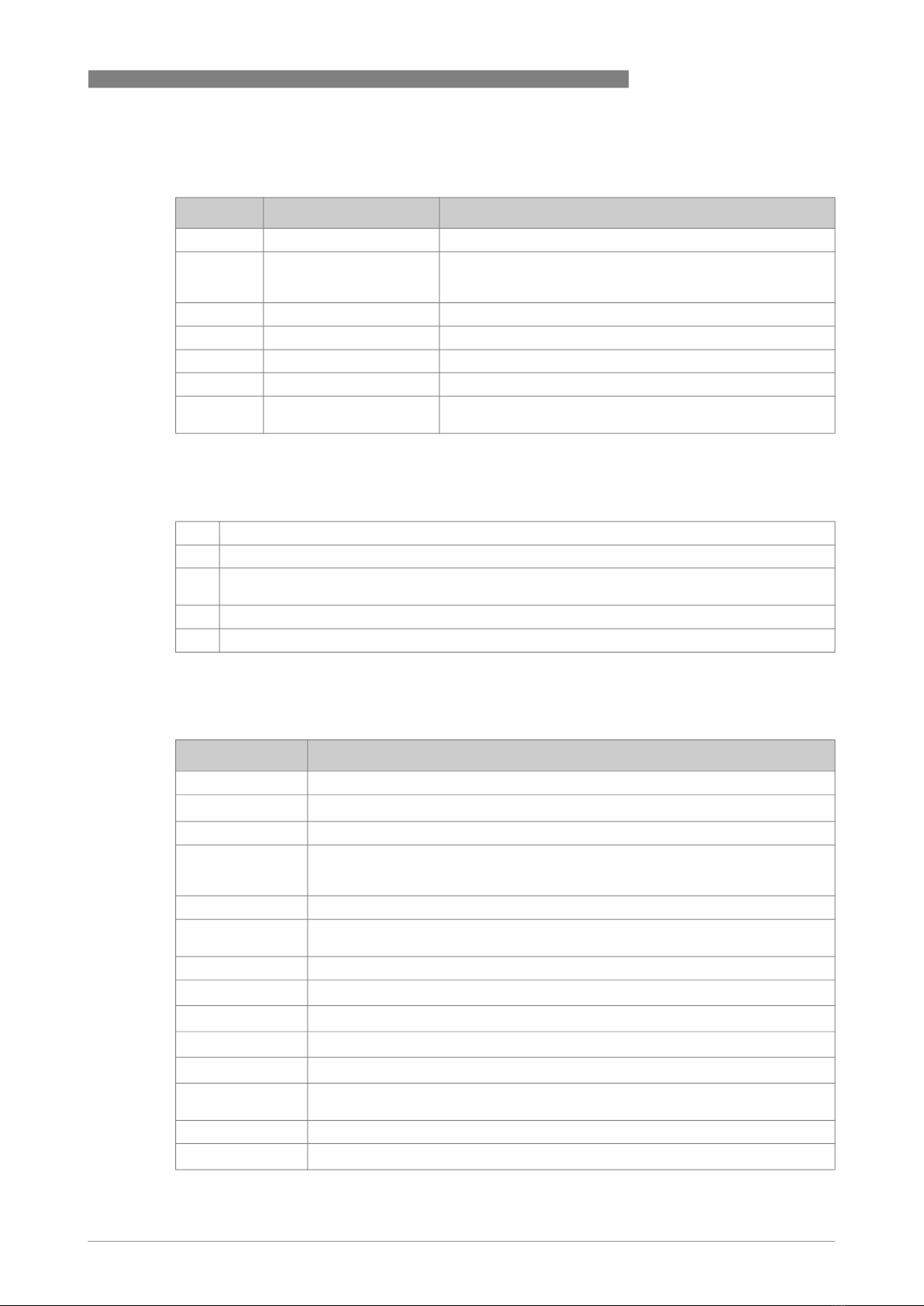
Code Description Applicable options for functional safe devices
ab Flow sensor type and size 02, 03, 04
d Nominal diameter VN02: 1, 2, 3, 5, 6
VN03: 4, 5, 6, 7, 8, A, B, C, D
VN04: E, F, G, H, K, L, M, N
g System design 1, 4, 5, 6, 8, A, B, C, E, R
h Signal converter model T, U
j Liner 0, 1, 2, G, H, K, S, U, V
k Electrodes 1, 2, 3, 4, 6, 7, B
p Cable 0 (for signal converter model = T)
1 (for signal converter model = U)
Table 1-7: Permitted flow sensor variants for functional safety
[1] KROHNE, IFC 400 Handbook.
[2] KROHNE, OPTIFLUX 4000 Handbook
[3] IEC 61508-1 to 7:2010 Functional safety of electrical/electronic/programmable electronic safety-
related
[4] KROHNE, OPTIFLUX Chemical Compatibility Guideline, 2021
[5] NAMUR, NE43: Standardization of the Signal Level for the Failure, 2003
Table 1-8: Related documentation
Term Description
Firmware Software embedded in the device
FIT Failure In Time (1x10⁻⁹ failures per hour)
FMEDA Failure Modes, Effects and Diagnostics Analysis
FRT Fault Response Time (diagnostic test interval + Fault Reaction Time).
This is the maximum time that is necessary for the current output to change to a
safe value when the safety function has an error condition.
HFT Hardware Fault Tolerance
High demand or
continuous mode Where the frequency of demands for operation made on a safety-related system is
greater than one time per year.
I/O Input / output
DD Rate for dangerous detected failure
DU Rate for dangerous undetected failure
SD Rate for safe detected failure
SU Rate for safe undetected failure
Low demand mode Where the frequency of demands for operation made on a safety-related system is
not greater than one time per year.
MTBF Mean Time Between Failures
PFDAVG Average Probability of Failure on Demand