Krome dispense AS-40 User manual


Introduction :
Thank you for a purchasing our professional product
and we believe it will operate to your satisfaction.
General instructions and precautions
Safety instructions:
Warning! Respect the basic safety instructions
given by the manufacturer. Take care of your
personal safety. Cooling equipment is designed for
flow type cooling of beverages. The supplier shall
not be liable for damages caused by improper use.
DO NOT USE THE MACHINE FOR ANY OTHER
PURPOSES THEN WHAT IT IS INTENDED FOR!
General safety rules
The manufacturer is not liable for damages caused by
actions that do not follow following these instructions.
CAUTION:
Before connecting the main electrical supply,
check if the voltage and frequency corresponds to
the specifications shown on the machine.
CAUTION:
Make sure the socket to connect the cooler is equipped
with sufficient circuit breaker (16A depending on the type)
according to CSN 33 1500 norm.
CAUTION:
Before any cleaning or maintenance, always
disconnect the machine from the electricity supply:
Put the main switch (thermostat) into the position
"O" and pull out the plug.
CAUTION:
Never insert tools or other objects into the
propeller fan.
CAUTION:
Never touch electrical components with wet or
damp hands.
CAUTION:
To ensure the performance of the cooling unit,
never block the air inlet.
CAUTION:
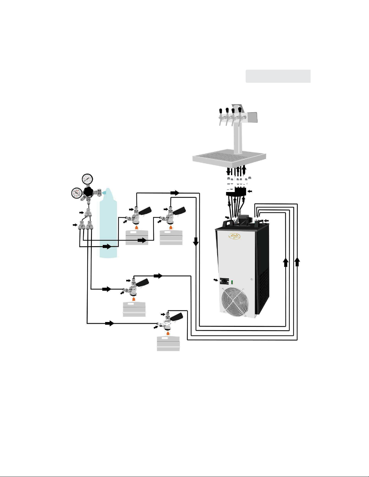
With the CWP-100 model, CWP-200, CWP-200 mobile,
CWP-300 and CWP-300 mobile models, they should
NEVER BE used if the door is opened. Otherwise,
there would be a distruption of air circulation and
the subsequent failure of the machine.
CAUTION:
All our equipment must be installed by
appropriately trained staff.
More detailed maintenance such as cleaning and
servicing the cooling system must be performed
by authorized technicians who are familiar with
cooling and electrical systems.
CAUTION:
If the supply cord is damaged, it must be replaced by the
manufacturer, its service technicians or similarly qualified
person in order to avoid dangerous situations.
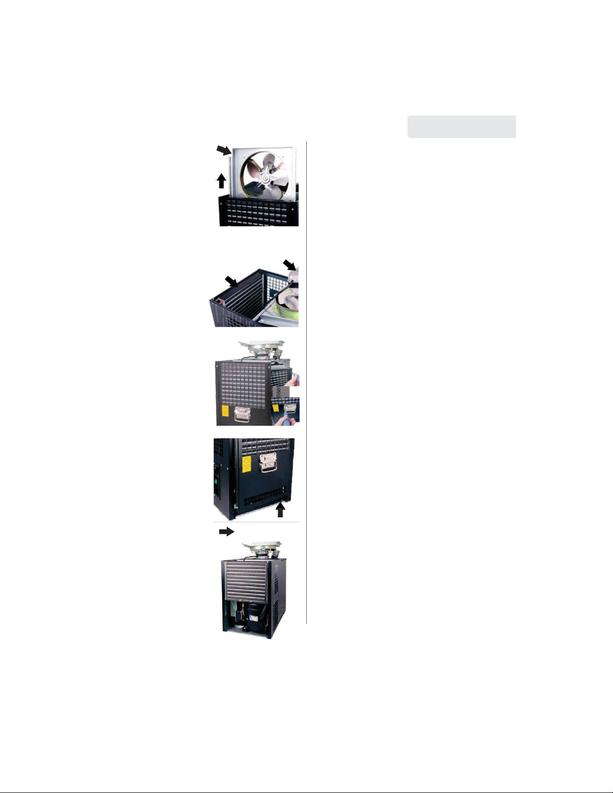
Installation and placement:
After unpacking, place the cooler so that the heat
generated by the cooling unit can be sufficiently
ventilated. The cooler MUST BE placed on a
horizontal surface.
COOLER MUST NOT BE PLACED ON ITS SIDE EVEN
DURING TRANSPORTATION.
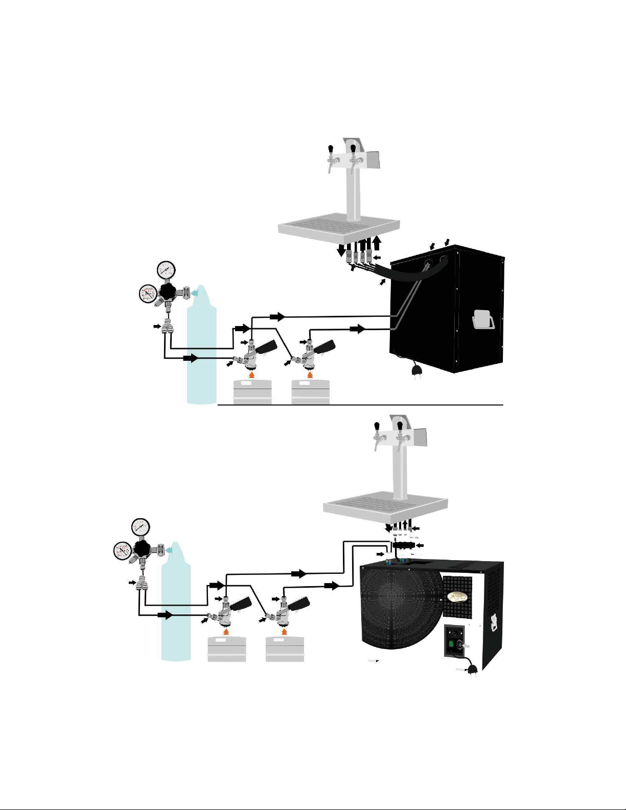
Conditions of operation:
Our cooling systems are designed to cool liquids with
flow type cooling . These machines have all the
features to ensure the health and safety of the user.
The machine should only be used in the premises of a
normal conditions stated in CSN 33 2000-3 norm. It
must not be placed near any heat source or direct
sunlight. Cooling tank (No. 11) MUST BE filled with
clean water and without any chemicals, right up to the
overflow. The machine achieves optimal performance
when used in ambient temperatures from 6°C to
28°C. For correct operation it is important to not cover
any of the ventilation holes.
DO NOT PLACE ANY OBJECTS ON THE COOLER THAT
WOULD BLOCK AIR CIRCULATION.
THE MACHINE MUST NOT BE PLACED NEAR ANY
HEAT SOURCE OR IN DIRECT SUNLIGHT.
Testing:
The product is supplied so that it is ready to use.
Warranty:
There is a 24 month warranty from the date of
purchase on all our equipment and related
components from our production. During this warranty
period we commit ourselves to replace any part free
of charge, which will be covered under the warranty
once recognized by the service center as faulty.
1.

Manufacturer agrees to correct any errors or defects
that occur when the cooling equipment is used
properly according to the instructions provided in the
ENGLISH
8.
instructions. The products used for commercial
purposes are warranted for 12 months from date
of purchase, unless otherwise agreed by special
5.
7.
12.
agreement.
Materials replaced under warranty are our
property and must be returned to by the customer.
Equipment Description:
1.recirculation pump
2.inlet of the beverage
3.outlet of the cooled beverage
4.fan
5.suction propeller
6.fan cover
7.condenser
8.cover of the electro panel
9.evaporator
10.cooling coil
11.plastic tank
12.motor compressor
13.overflow
2.
8
.
5
.
9.
6
.
4
. 10.
1.
13.
12.
11.
3.
7.
Model series of CWP:
11.
3.
10.
1.
4.
6.
Connection:
1. Fill the plastic tank
(No.11) with water right
up to the overflow (No.13)
CAUTION:
After connecting the cooling
coil the water level may
drop in the plastic tank, so
check again and add water
if necessary.
2. Connect the cooling ma-
Python 4+2
chine with dispense
tower (output) and
dispense heads (input).
See page 13 and 14.
CAUTION:
Due to condensation there can be a small amount
of water flowing away through the overflow.
We recommend to connect the overflow with a
collecting container.
Note:
For the connection of tubes for the beverage use only
9.
13.
2.
fittings and clips specified by the supplier.
Use a calibrated tube 6.7 x 9.5 mm.
AFTER THE CONNECTION CHECK IF ALL THE JOINTS
ARE PROPERLY SEALED.
2

Placement of the thermostat:
3. Model AS has a
mechanical thermostat
located on the front of
the cooler.
See picture
4. Model CWP
See picture
Temperature and setting:
0= off
No.1 minimum cooling stage
(temperature of beverage will
be about 10 ° C)
No.7 maximum cooling stage
(temperature of beverage will
be about 4 ° C)
Once the following steps have been taken, you
can start up the cooling unit by connecting the
power cord and switching on the main switch.
How to work with
the fittings:
7.
Push the tube into the
fitting firmly (about 1.5 cm).
The tube must be cut
straight to avoid any
imperfect
connections. If
you can´t insert the tube in,
you need to moisten the
end.
Disconnection:
8.
Hold the gray ring to-
wards the body of the
fitting and pull out the
tube.
CAUTION:
grey ring
If you don´t hold the grey
ring while pulling the tube,
the fitting will cut even
more into the tube.
THE TUBE MUST NOT BE UNDER PRESSURE WHEN DISCONNECTING !
Regular and the scheduled maintenance services:
Regarding routine maintenance, the information
contained in this manual is intended for a regular
operating staff, which must be properly trained.
Regarding any emergency or scheduled
maintenance, the contained information is
intended for professional staff only.
The basic safety instructions:
Before any work on the machine, it must be
disconnected from the main electrical supply.
Cleaning of the machine:
Before any cleaning of the machine, it must be
disconnected from the main electrical supply. Cleaning of
the condenser (No.7) must be performed only by a
qualified person at least 1x per month by sweeping or by
CO2 pressure. Perform the cleaning (sanitizing)of a
stainless steel coil (No. 10) professionally with the use of
for example DOPILINE or TM Desana solution, and
always after a minimum of fourteen days.
Cleaning of the condenser:
9. By pulling upwards you
will remove the fan cover
(No.7) from metal slides.
7.
3

fan cover
direction of pulling
10. Cover (No. 7)
Take off the fan.
condenser
11. Unscrew the fastening
screws from the cooler on
the side where the con-
denser is placed.
(picture 3.1 and 3.2.)
12. First, pull out the
loosen cover about 3 cm
in a upward direction
(picture 4.1.), then pull to
the side (pic. 4.2).
Loosen the other side of
the cover so you can pull
out the whole cover from
the metal slides.
4.2. direction of pulling
13. Now you can clean the
condenser by brushing or
by the air pressure
from both sides.
fan cover
3.1.
3.2.
4.1. direction
of pulling
ENGLISH
Periodic checks
check, if the power supply plug is firmly
plugged into the socket.
check that the machine is not exposed to
radiant heat
check the level and cleanliness of the water bath
in the plastic container (No.11) (after six months of
operation we recommend to replace the
water bath)
the condenser of the cooling unit should
be cleaned regularly
sanitizing
When sanitizing do not forget to also sanitize
the dispensing tap and the dispense head. You
need to disassemble them, then soak in a
chemical solution and clean thoroughly to
remove any residue left by the beer.
Special maintenance:
This chapter provides information for a
qualified persons only.
check the correct functioning of the circuit
broker and a status of power cord.
check whether there is a noticable change in a
machine operation.
If you need to order replacement parts, it is always
necessary to state the type and serial number of
the machine. This is written on the label.
Electrical connection:
The machine should be connected to the power
supply 220-240V 50Hz, 16A fuse. Plug circuit wiring
must comply with applicable regulations of IEC, EN
and ISO standards. If the power cord (cable) is
damaged, it must be replaced by the manufacturer,
its service agent or similarly qualified person in order
to avoid dangerous situations.
Potential areas of risk, risks which cannot be
removed.
Risks related to the electricity:
Potential risks are removed thanks to the
construction of the electrical system according to
CSN 331500, EN, and ISO norms.
Note:
Electrical machine must be checked within scheduled
dates according to CSN norm by the authorized person.
Service, spare parts, required inspections and check ups
are carried out and provided by the Lindr company.
4

Connection A: AS - 40 (coil
2x) pressurizing CO2/ N2
1. Beverage inlet
2. Beverage outlet (the beverage runs through
the python tubing No.11 illustration)
3.Dispense head (S-type, A-type, M-type)
4.Plastic fitting F 5/8 x9.5mm
5.Plastic fitting F 5/8 x 8 mm
6. Plastic fitting splitter 8 x 8 x 8mm
7. Pressure reducer 1-way N2/ CO2
8.Beverage
9.Plastic fitting JG SS 9.5 x8mm
10.Plastic fitting JG straight 12.7 x8mm
7.
Beverage
6.
CO
2/
N
2
4. 4.
CO
2/
N
2
3.
5.
3.
5.
or compressor
8.
8.
10.
9.
11.
Beverage
1.
2.
Connection with dispense tower B: AS - 80 (coil 2x)
1. Beverage inlet
2. Beverage outlet (the beverage runs through
the python tubing 2+2 No.12 illustration)
3.Tray for the clarifier
4. Dispense head (S-type, A-type, M-type)
5. Plastic fitting F 5/8 x9.5mm
6. Plastic fitting F 5/8 x 8 mm
7. Plastic fitting splitter 8 x 8 x 8mm
8. Pressure reducer 1-way N2/ CO2
9. Beverage
8.
10. Plastic fitting JG SS 9.5 x8mm (2x)
11. Rychlospojka JG straight 12.7 x8mm (2x)
1.
Beverage
7.
CO
2/
N
2
5.
5.
Beverage
CO
2/
N
2
6. 4.
6. 4.
or compressor
9. 9.
11.
10.
12.
2.
3.
5

Connection with dispense tower C: CWP - 200 (coil 4x)
pressurizing CO2/ N2
1.Beverage inlet
2.Beverage outlet (the beverage runs through the
python tubing 4+2 No.12
illustration) 3. Thermostat
4. Dispense head (S-type, A-type, M-type)
5.Plastic fitting F 5/8 x9.5mm
6.Plastic fitting F 5/8 x 8 mm
7.Plastic fitting splitter 8 x 8 x 8mm (3x)
8.Pressure reducer 1-way N2/ CO2 N2/ CO2
9.Beverage
10. Plastic fitting JG SS 9.5 x8mm (4x)
11. Plastic fitting JG straight 12.7 x8mm (2x)
8.
Beverage
Beverage
7. 5. 5.
6. 4.
6.
4.
7.
9.
9.
CO
2/
N
2
or
compressor
Beverage
3.
5.
CO
2/
N
2
6.
4.
9.
5.
6.
4.
9.
ENGLISH
11.
10.
12.
2.
1.
Beverage
6

Before calling service:
Problem
Caus
e
How to fix it
The machine is too noisy
The machine does not work:
The machine is turned
on, but does not cool:
Fittings do not seal properly
There is a fallen
object in the machine.
There is a fallen object
in the area of the fan.
The power cable is
not connected.
Socket does not work.
The main switch is not
turned on or the
thermostat is set to ,,0 ”.
Ventilation holes
are covered.
The machine has a
dirty condenser.
The tube is not
inserted correctly.
damage to the tube
Remove the object that is not in contact with
the cooling machine.
Remove the object from the fan area.
Connect the power cord into the socket.
Turn on the power switch and set the
thermostat to the desired value.
Remove anything from the vent holes.
Remove the coarse dirt and wipe off the dust.
Pull out the tube, check for any sharp edges,
and if there are, cut with knife.
Pull out the tube and shorten 2cm.
If, after the above recommended checks the fault
still persists, please contact customer service.
Do not forget to specify the following:
type of defect
type of product
product serial number (listed on the label)
Ordering parts:
ALWAYS USE ORIGINAL PARTS.
The manufacturer or supplier does not take any
res-ponsibility for parts which are not original or re-
commended by the manufacturer.
Technical specifications:
The technical label is located on the external front side
(under the control panel) of the machine or on the inside
divider. The CWP -100, CWP-200, CWP 300, CWP - 200
mobile and CWP-300 mobile have the label on the
outside shell on the front of the machine.
7

MODEL /
AS-40 AS-80
AS-110
AS-160
AS-200
CWP
CWP 200
CWP 200
CWP 300
CWP 300
TECH. DATA
GREEN LINE GREEN LINE
100
GREEN LINE GREEN LINE
GREEN LINE
GREEN LINE
mobile mobile
Output in HP 1/6
1/4
3/8
3/4
7/8 3/8
3/4
3/4
7/8
7/8
Output in l/hour
40l/ h. 80l/ h.
110l/ h.
160l/ h.
200l/ h.
100l/ h.
200l/ h.
200l/ h.
300l/ h.
300l/ h.
22°C= 7°C
The min. tempera-
5-8°C
5-8°C 5-8°C
5-8°C
5-8°C 5-8°C
5-8°C
5-8°C
5-8°C
5-8°C
ture of beverage
Number of cooled
2
2-4 2-6 2-8 2-8
3
4-6
2
4-8
2
beverages
Power supply
230V/ 230V/ 230V/ 230V/ 230V/ 230V/ 230V/ 230V/ 230V/ 230V/
50Hz
50Hz
50Hz
50Hz
50Hz
50Hz 50Hz
50Hz
50Hz
50Hz
Amperage
1.27A 1.70A 2.90A 4.00A
4.50A
3.40A 4.00A 4.00A 4.50A
4.50A
Power input
292W
391W
667W 920W 1035W
782W
920W
920W
1035W
1035W
or wattage
Ice bank
4-8kg
5-10kg
10-20kg
10-30kg
10-30kg
0-2kg 0-5kg 0-5kg 0-5kg 0-5kg
Refrigerant
R - 134a R - 134a
R - 134a
R - 290
R - 290
R - 134a
R - 290
R - 290
R - 290
R - 290
Capacity of water
14l
20l
38l
58l
58l
14l
20l
20l
38l
38l
tank
Draught of re-
1.2m 7m 7m
8m
8m
7m
7m 7m
8m
7m
circulation pump
Weight
18.8kg 29.0kg 34.0kg 51.0kg 51.0kg 30.5kg 49.5kg 53.0kg 56.0kg 60.0kg
Dimensions
440mm
530mm
530mm
631mm
631mm 270mm
330mm
330mm
418mm
415mm
of cabinet/ width
Dimensions
395mm
474mm
474mm
595mm
595mm 706mm
771mm
1491
773mm
1519
of cabinet/ height
Dimensions
270mm
330mm
330mm
422mm
422mm 355mm
421mm
463mm
507mm
548mm
of cabinet/ depth
8
This manual suits for next models
9
Popular Water Dispenser manuals by other brands

California Faucets
California Faucets 9628SS installation instructions

SENTRY II
SENTRY II 959TA14 Series Operation and maintenance manual

BRIO
BRIO CLBL420 user manual

GE
GE GXSF30V Owner's Manual & Installation Instructions

Zazen
Zazen Alkaline Water system Installation & Care Guide

Bunn
Bunn H5E specification

Watts
Watts LC-100 Series Installation, operation and maintenance

IBC Water
IBC Water AS36700 Installation & operating instructions

Atlantis
Atlantis aT210 installation instructions

Hague Quality Water
Hague Quality Water Maximizer 400 Installation and service manual

Kemper
Kemper KHS CoolFlow operating instructions

Oasis
Oasis MAXXFILL FLEX user guide