DG..S · Edition 02.24
EN-2
2 CHECKING THE USAGE
To monitor rising and falling pressure.
Positive pressure
Nega-
tive
pres-
sure
Differ-
ential
pres-
sure
DG..S NH3, O2, air – –
This function is only guaranteed when used within
the specified limits– see page 6 (9 Technical
data). Any other use is considered as non-compliant.
2.1 Type code
DG Pressure switch for gas
6
Adjusting range 40–600Pa (0,4–6mbar)
10 Adjusting range 100–1000Pa (1–10mbar)
50 Adjusting range 0,25–5 kPa (2,5–50mbar)
150 Adjusting range 3–15 kPa (30–150mbar)
500
Adjusting range 10–50 kPa (100–500mbar)
SPositive pressure for oxygen and ammo-
nia
GWith gold-plated contacts
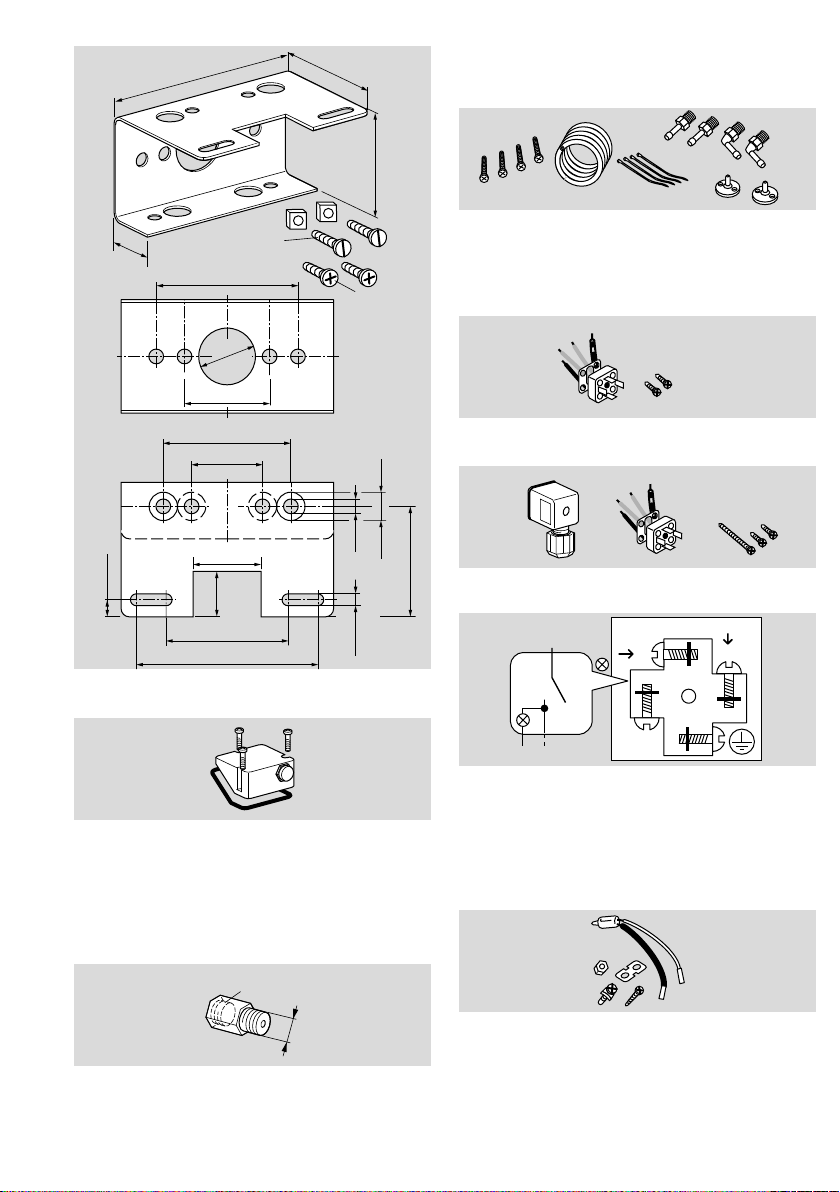
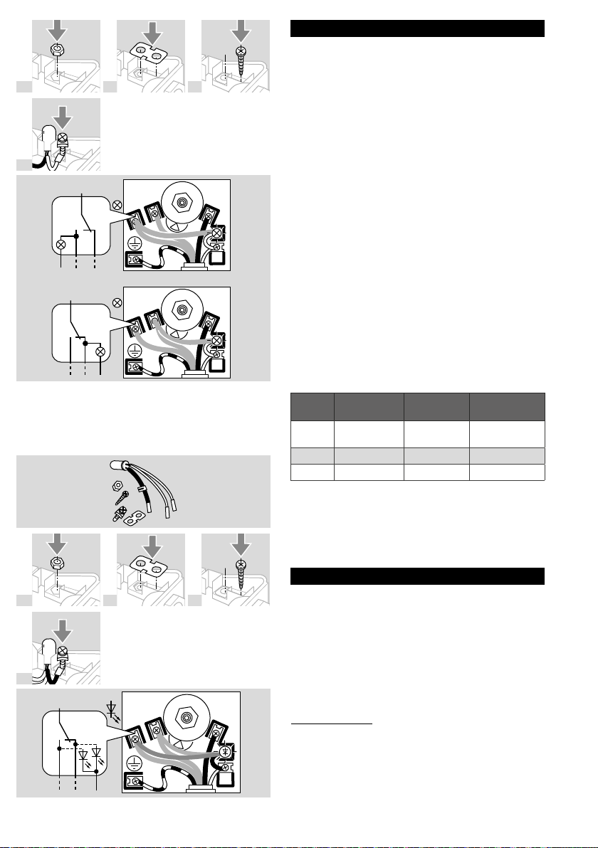
-3 Electrical connection via screw terminals
-4 Electrical connection via screw terminals,
IP 65
-5 Electrical connection via 4-pin plug,
without socket, IP 54
-6 Electrical connection via 4-pin plug, with
socket, IP 54
-9 Electrical connection via 4-pin plug, with
socket, IP 65
K2 Red/green pilot LED for 24V DC/AC
TBlue pilot lamp for 230V AC
T2
Red/green pilot LED for 110 to 230V AC
NBlue pilot lamp for 120V AC
AExternal adjustment
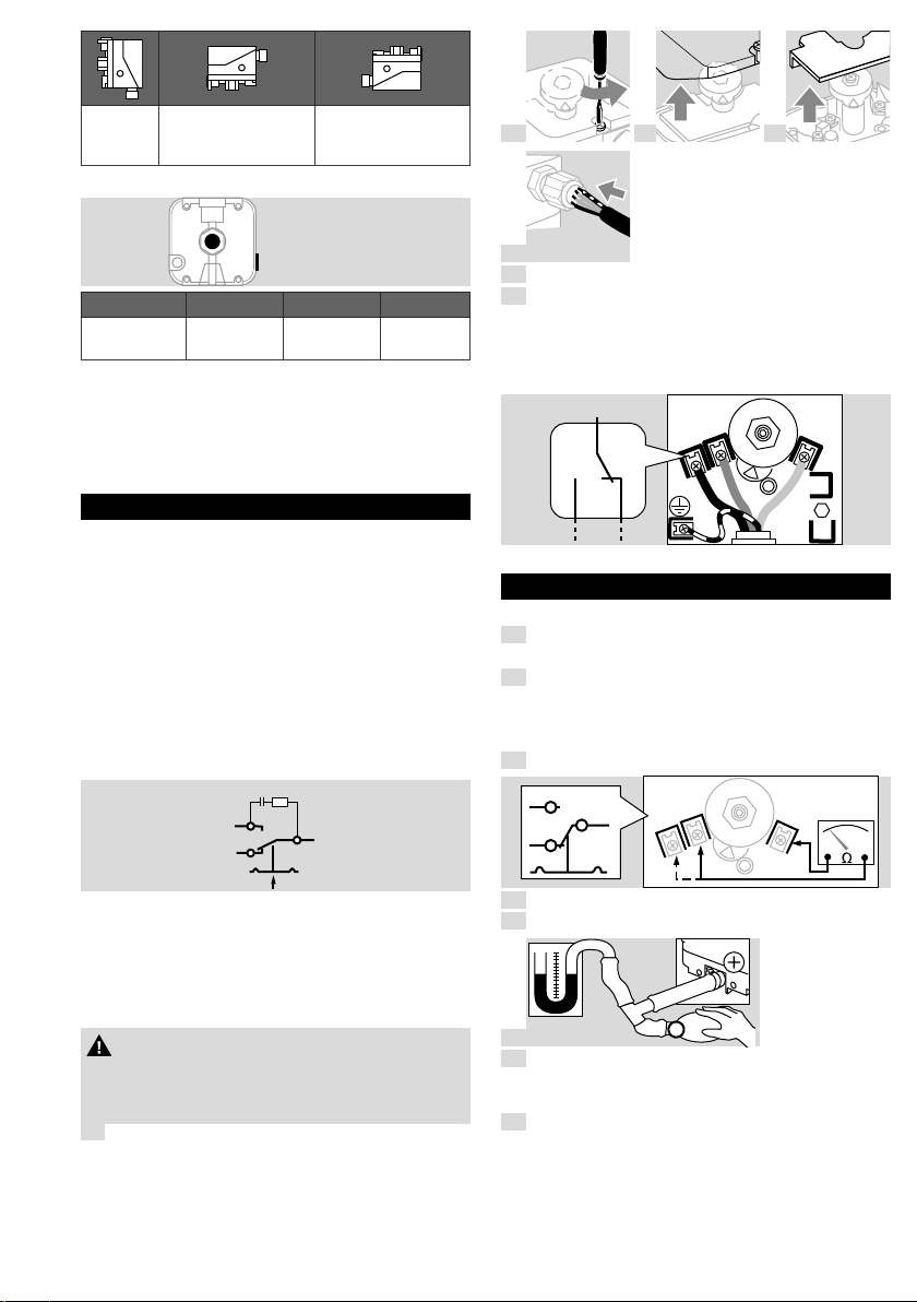
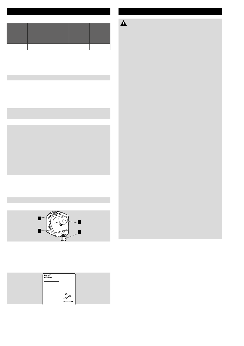
2.2 Part designations
1
2
3
4
1 Upper housing section with cover
2 Lower housing section
3 Hand wheel
4 M16 cable gland
2.3 Type label
DG
CE 2
13
Made in Germany
Max. inlet pressure = withstand pressure, mains
voltage, ambient temperature, enclosure: see type
label.
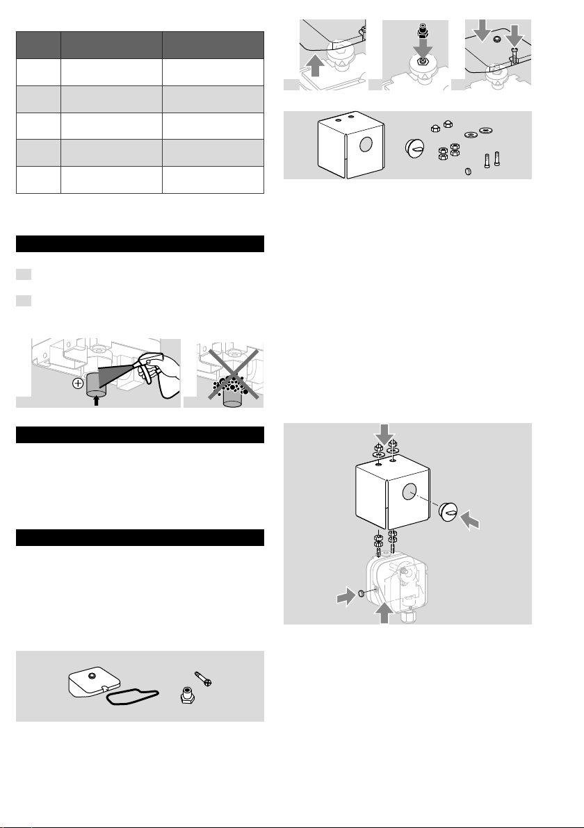
3 INSTALLATION
CAUTION
Please observe the following to ensure that the
unit is not damaged during installation:
– Dropping the device can cause permanent
damage. In this event, replace the entire device
and associated modules before use.
– Use approved sealing material only.
– Check max. ambient temperature– see page
6 (9.1 Ambient conditions).
– As the temperature increases, the diffusion rate
of NH3through the diaphragm also increases
which can cause corrosion of the contacts. For
this reason, query the closed contacts for
opening.
– The medium NH3must not condense as this
can lead to increased corrosion of the lower
section (pressure supply can become blocked)
and deformation of the diaphragm (causing the
switching point to shift).
– Continuous operation at high temperatures
accelerates the ageing of elastomer materials. In
places where a high thermal capacity is
required, thermal equipment trips must be
installed upstream of theDG.
– The service life will be shorter if subject to ozone
concentrations exceeding 200μg/m3.
– When installing outdoors, place the pressure
switch in a roofed area and protect from direct
sunlight (even IP65 version). To avoid conden-
sation, the cover with pressure equalization
element can be used. See accessories.
– Condensation or vapours containing silicone
must not be allowed to get into the housing. If
possible, install pipework with an ascending
gradient. Otherwise, there is a risk of icing of
condensation at subzero temperatures, the
switching point shifting or corrosion in the
device which can lead to malfunctions.
– Avoid strong impact on the unit.
➔The DG must not be in contact with masonry.
Minimum clearance 20mm.
➔Ensure that there is sufficient installation space.
➔Ensure unobstructed view of the hand wheel.
3.1 Installation position
Installation in the vertical or horizontal position, or
sometimes upside down, preferably with vertical
diaphragm. If installed in a vertical position, the
switching pointpSwill correspond to the scale
valueSK set on the hand wheel. If installed in
another position, the switching pointpSwill change
and no longer correspond to the set scale valueSK.
Switching pointpSmust be checked.