3
Indications for use:
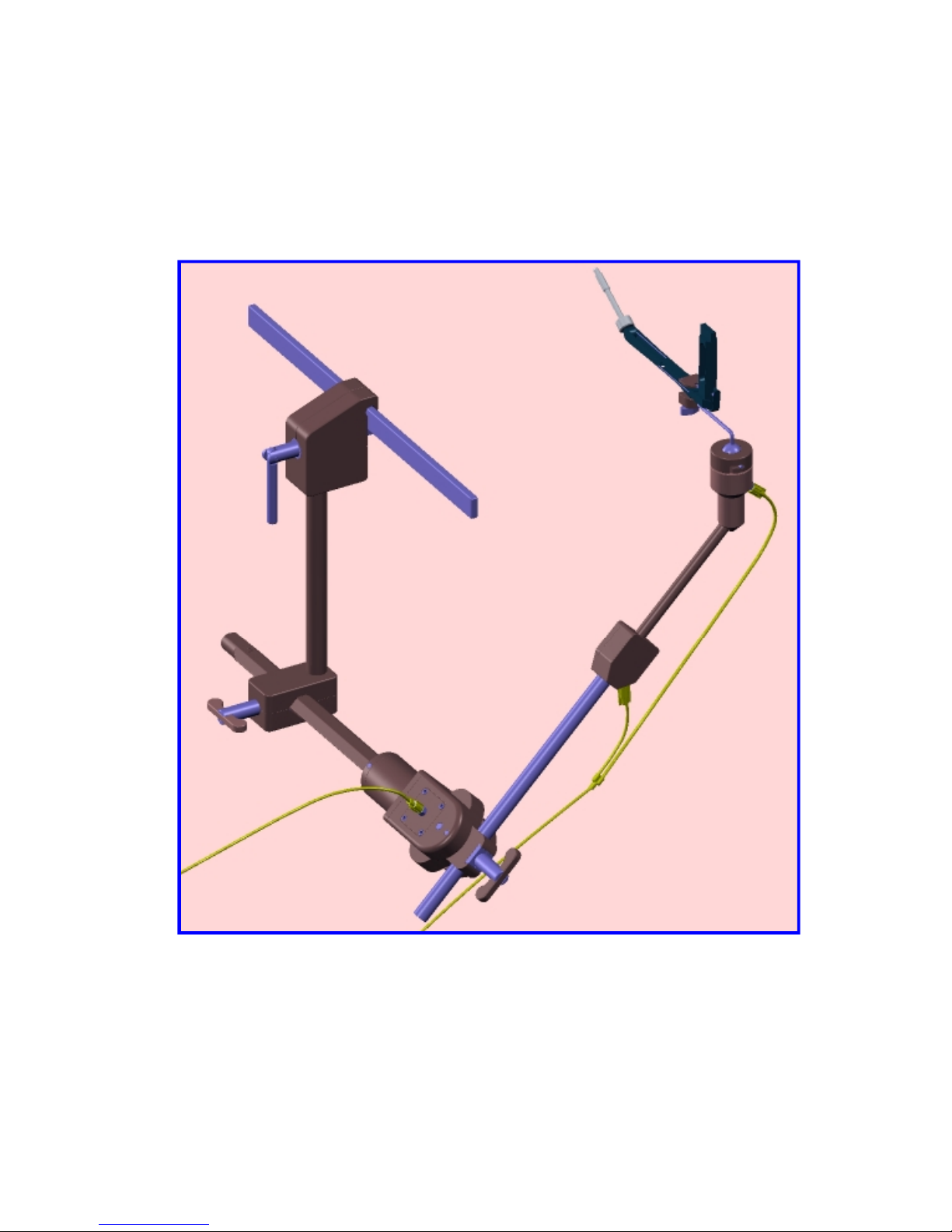
The Kronner Side-Kick Uterine Manipulator Holder is intended to assist the surgical
staff in mounting, positioning and holding a uterine manipulator during gynecological
laparoscopic surgical procedures. It is intended for use by trained operating room
personnel in an operating room environment.
Contraindications:
1. Adapter unavailable for chosen manipulator
2. Table rail unreliable
3. Gas supply is unreliable or unavailable at required pressure
4. Intended surgery does not require use of a uterine or vaginal manipulator. See the uterine
manipulator manufacturers’literature regarding instruction for use, indications, contraindications
and safety information.
Warnings:
1. Do not use with pressure greater than 150 psi.
2. Do not detach the gas supply module from the gas supply while the manipulator is attached.
3. Do not shut off the gas supply module switch while the manipulator is attached.
4. Do not use substitute flexible gas lines.
5. Do not use if gas leaks are detected.
6. Use only the specified adapter with the chosen manipulator.
7. On older operating tables with motorized perineal rests, make sure the rest is in the down
position before adding the main pivot and the remainder of the assembly.
8. The gas module switch must be in the “on” position during use.
9. Do not use the sterile lines if the package is damaged or the 3 year expiration date is passed.
10. Do not attach the holder to a manipulator of a patient that is not under anesthesia or otherwise
immobilized.
11. Use only nitrogen or compressed air gas.
12. In the event the Side-Kick was disassembled without turning off the gas module switch, the
pneumatic joints may still be pressurized. To decompress, attach a male luer from a
branched gas line with one short branch disconnected or use a syringe with the plunger
removed.
13. Do not attach the Sidekick rail grip over an attachment of the table rail to the table.
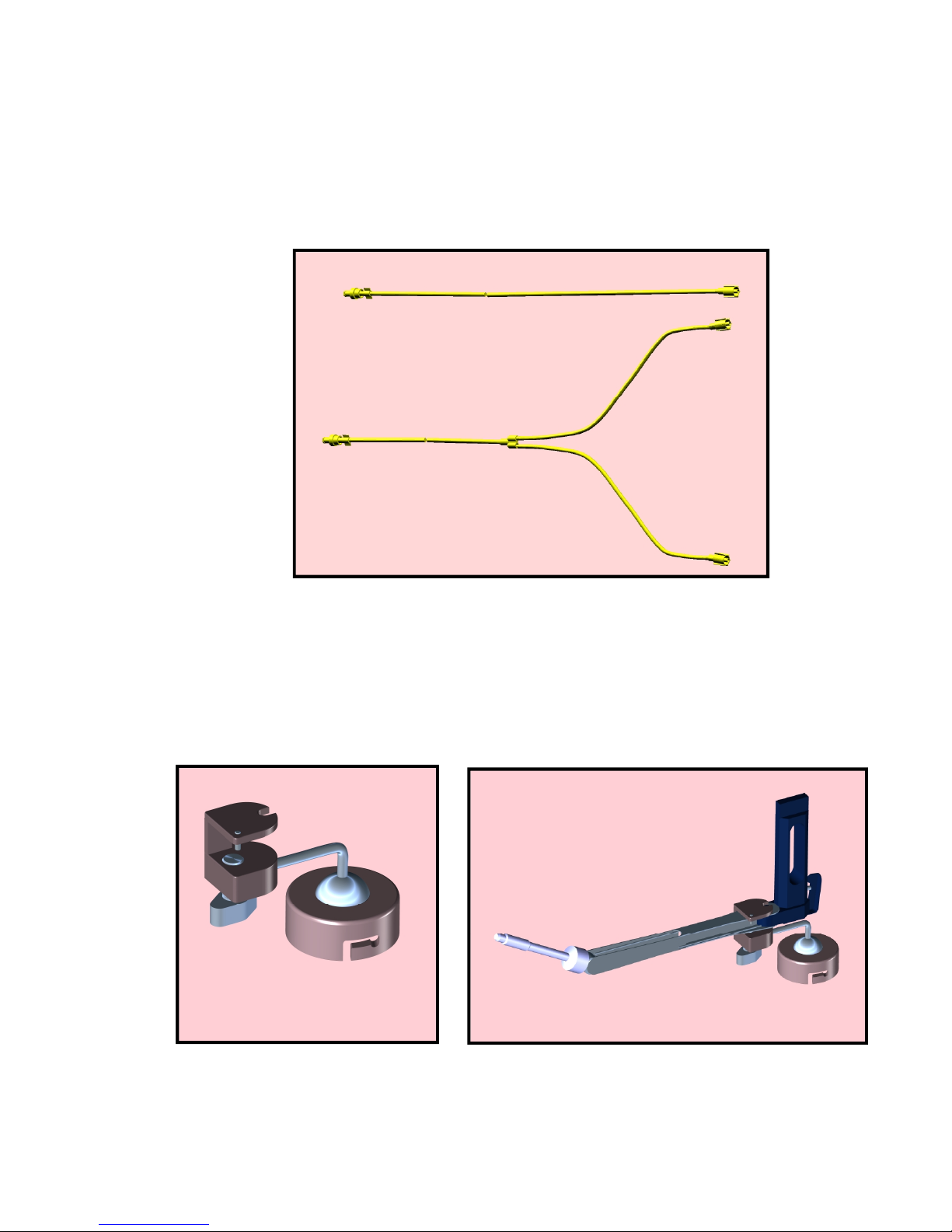
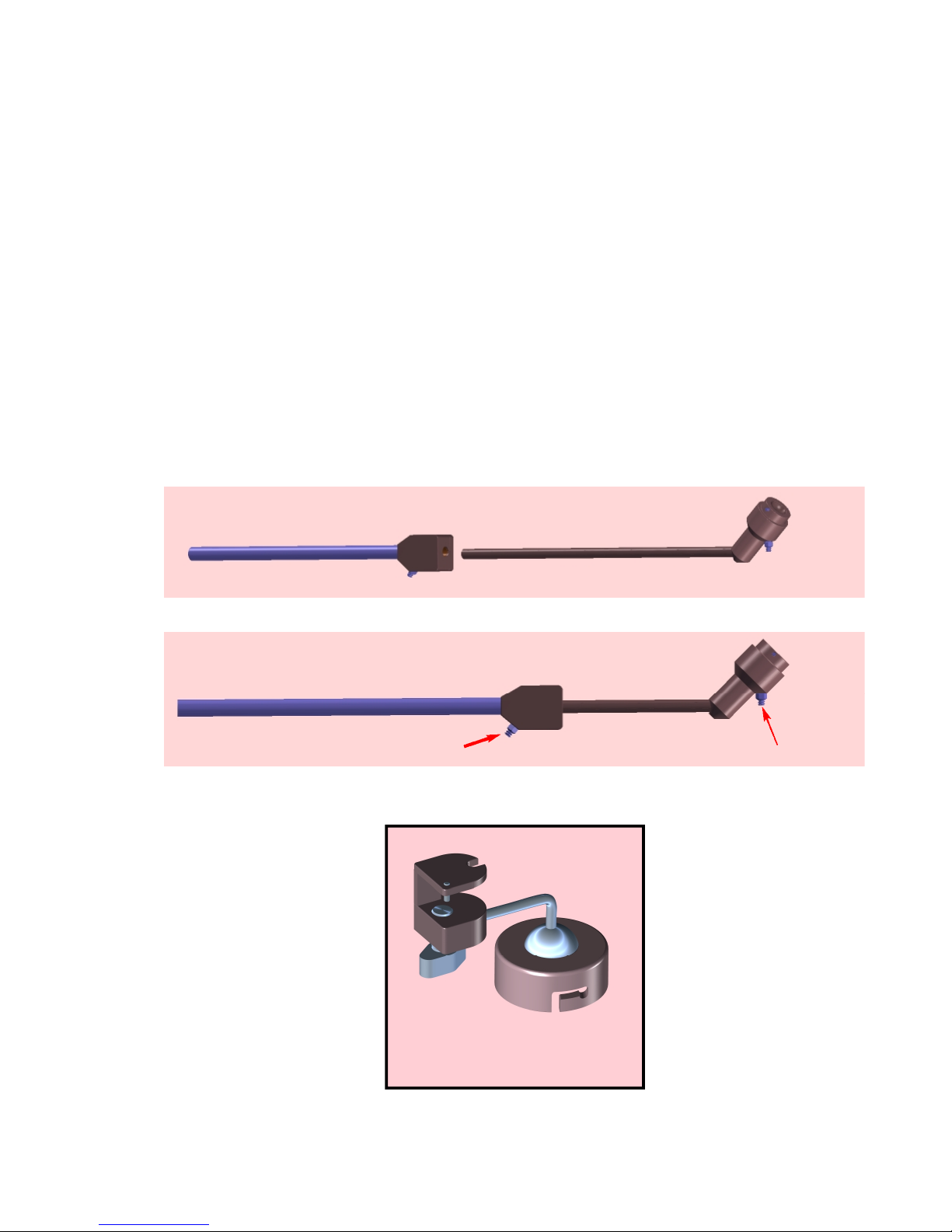
14. Attach the single gas line to the pivot and the branched line to the arm.
15. Remove the Sidekick arm before raising the lower end of the operating table.
16. Do not attach a gas line to a uterine manipulator, extreme danger.
Precautions:
1. Verify that the operating table rail is not loose.
2. Verify that the operating table end can be lowered or removed.
3. Restrain the patient from sliding on the table when the table is tilted.
4. Prevent the gas supply line from damage due to moving objects.
5. Check the uterine manipulator for defects.
6. Verify that the gas supply is steady and available at 140-150 psi.
7. Securely attach all flexible gas lines to the gas supply module and to the holder.
8. Read the instruction manual prior to use.
9. When making a patient transfer to or from the operating table to a cart with Sidekick in between,
remove Sidekick or protect it from the cart.
10. Always support a connected manipulator when stepping on the gas pedal.