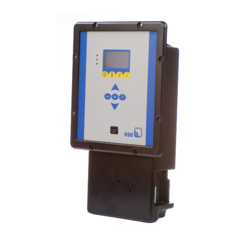
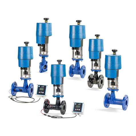
KSB EMV Series Installation instructions

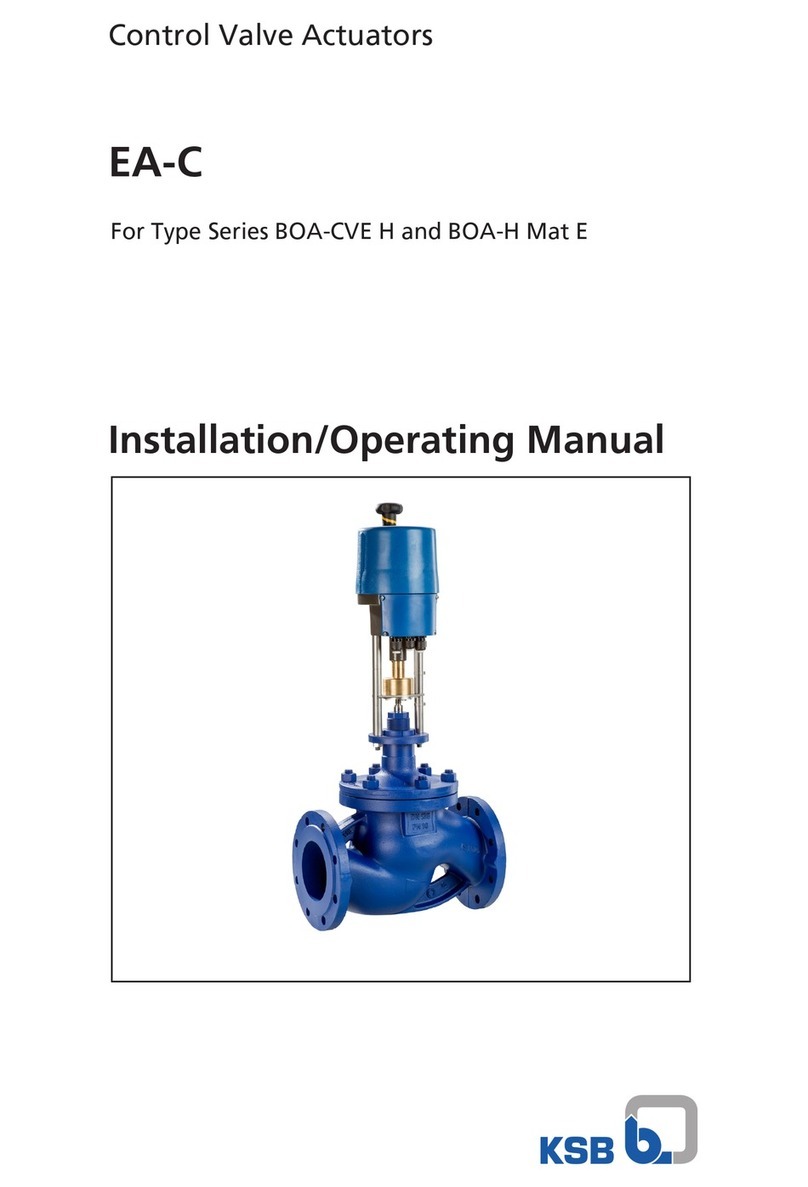
Control Valve Actuators
EMV
For the BOA-Control PIC Type Series
Installation/Operating Manual

Legal information/Copyright
Installation/Operating Manual EMV
Original operating manual
All rights reserved. The contents provided herein must neither be distributed, copied, reproduced,
edited or processed for any other purpose, nor otherwise transmitted, published or made available to a
third party without the manufacturer's express written consent.
Subject to technical modification without prior notice.
© KSB SE & Co. KGaA, Frankenthal 11/10/2021

Contents
3 of 54
EMV
Contents
1 General.................................................................................................................................................... 5
1.1 Principles ...........................................................................................................................................................5
1.2 Target group.....................................................................................................................................................5
1.3 Symbols .............................................................................................................................................................5
1.4 Key to safety symbols/markings.......................................................................................................................5
2 Safety...................................................................................................................................................... 7
2.1 General..............................................................................................................................................................7
2.2 Intended use .....................................................................................................................................................7
2.2.1 Prevention of foreseeable misuse.......................................................................................................7
2.3 Personnel qualification and training...............................................................................................................7
2.4 Consequences and risks caused by non-compliance with this operating manual........................................8
2.5 Safety awareness ..............................................................................................................................................8
2.6 Safety information for the user/operator.......................................................................................................8
2.7 Safety information for maintenance, inspection and installation ................................................................8
2.8 Unauthorised modes of operation..................................................................................................................8
3 Transport/Storage/Disposal .................................................................................................................. 9
3.1 Checking the condition upon delivery............................................................................................................9
3.2 Transport...........................................................................................................................................................9
3.3 Storage/preservation........................................................................................................................................9
3.4 Disposal ...........................................................................................................................................................10
4 Description............................................................................................................................................ 11
4.1 General description ........................................................................................................................................11
4.2 Designation.....................................................................................................................................................11
4.3 Name plate......................................................................................................................................................12
4.4 Design details..................................................................................................................................................12
4.5 Function ..........................................................................................................................................................13
4.6 Noise characteristics .......................................................................................................................................13
5 Installation............................................................................................................................................ 14
5.1 Safety regulations...........................................................................................................................................14
5.2 Checking prior to installation........................................................................................................................14
5.2.1 Dimensions and weights of actuators ..............................................................................................15
5.3 Installation position........................................................................................................................................16
5.4 Manual override .............................................................................................................................................17
5.5 Mounting the EMV211 actuator....................................................................................................................19
5.5.1 Mounting the actuator......................................................................................................................19
5.5.2 Electrical connection..........................................................................................................................19
5.6 Mounting the EMV212/144, EMV 212/146 and EMV212/147 actuators ......................................................22
5.6.1 Mounting the actuator......................................................................................................................22
5.6.2 Electrical connection..........................................................................................................................22
5.7 Mounting the EMV212/148 and EMV212/150 actuators..............................................................................24
5.7.1 Mounting the actuator......................................................................................................................24
5.7.2 Electrical connection..........................................................................................................................25
5.8 Mounting the EMV213/145 and EMV213/147 actuators..............................................................................26
5.8.1 Mounting the actuator......................................................................................................................26
5.8.2 Electrical connection..........................................................................................................................26
5.9 Mounting the EMV213/148 and EMV213/150 actuators..............................................................................27
5.9.1 Mounting the actuator......................................................................................................................27
5.9.2 Electrical connection..........................................................................................................................28
5.10 Mounting the EMV311 and EMV312 actuators............................................................................................29
5.10.1 Mounting the actuator......................................................................................................................29
5.10.2 Electrical connection..........................................................................................................................29

Contents
4 of 54 EMV
6 Commissioning/Start-up/Shutdown................................................................................................... 30
6.1 Prerequisites for commissioning/start-up......................................................................................................30
6.2 Commissioning/Start-up.................................................................................................................................30
6.2.1 Commissioning/ starting up the EMV211/146 and EMV211/147 actuators ...................................30
6.2.2 Commissioning/ starting up the EMV212/146 and EMV212/147 actuators ...................................30
6.2.3 Commissioning/ starting up the EMV212/144 and EMV212/145 actuators ...................................30
6.2.4 Commissioning/ starting up the EMV212/148, EMV212/150, EMV213/145, EMV213/147,
EMV213/148, EMV213/150 actuators ................................................................................................32
6.2.5 Commissioning/ starting up the EMV311 and EMV312 actuators .................................................33
6.3 Operating limits..............................................................................................................................................34
6.3.1 Ambient temperature........................................................................................................................34
6.4 Shutdown........................................................................................................................................................34
6.4.1 Measures to be taken for shutdown ................................................................................................34
6.5 Returning to service .......................................................................................................................................34
7 Servicing/Maintenance........................................................................................................................ 35
7.1 Safety regulations...........................................................................................................................................35
7.2 Removing the actuator ..................................................................................................................................35
7.2.1 Removing the EMV211 actuator .......................................................................................................35
7.2.2 Removing the EMV212/144, EMV 212/146 and EMV212/147 actuators..........................................36
7.2.3 Removing the EMV212/148 and EMV212/150 actuators .................................................................37
7.2.4 Removing the EMV213/145 and EMV213/147 actuators .................................................................38
7.2.5 Removing the EMV213/148 and EMV213/150 actuators .................................................................38
7.2.6 Removing the EMV311 and EMV312 actuator.................................................................................39
7.3 Maintenance/inspection.................................................................................................................................39
7.4 Lubrication......................................................................................................................................................39
7.5 Cleaning ..........................................................................................................................................................39
7.6 Mounting the actuator ..................................................................................................................................40
7.7 Spare parts stock.............................................................................................................................................40
8 Trouble-shooting.................................................................................................................................. 41
8.1 Display of EMV211/145...................................................................................................................................41
8.2 Display of EMV211/146 and EMV211/147 .....................................................................................................42
8.3 Display of EMV212/144, EMV212/145, EMV212/146 and EMV212/147........................................................43
9 Related Documents.............................................................................................................................. 44
9.1 Wiring diagrams .............................................................................................................................................44
10 EU Declaration of Conformity............................................................................................................. 48
11 EU Declaration of Conformity............................................................................................................. 49
12 EU Declaration of Conformity............................................................................................................. 50
Index ..................................................................................................................................................... 51

1 General
5 of 54
EMV
7138.82/01-EN
1 General
1.1 Principles
This operating manual is valid for the type series and variants indicated on the front
cover.
The operating manual describes the proper and safe use of this equipment in all
phases of operation.
The name plate indicates the type series and size as well as the main operating data
and the serial number. The serial number uniquely describes the product and is used
as identification in all further business processes.
In the event of damage, immediately contact your nearest KSB service facility to
maintain the right to claim under warranty.
1.2 Target group
This operating manual is aimed at the target group of trained and qualified specialist
technical personnel.
1.3 Symbols
Table1: Symbols used in this manual
Symbol Description
✓Conditions which need to be fulfilled before proceeding with the
step-by-step instructions
⊳Safety instructions
⇨Result of an action
⇨Cross-references
1.
2.
Step-by-step instructions
Note
Recommendations and important information on how to handle
the product
1.4 Key to safety symbols/markings
Table2: Definition of safety symbols/markings
Symbol Description
!DANGER
DANGER
This signal word indicates a high-risk hazard which, if not avoided,
will result in death or serious injury.
!WARNING
WARNING
This signal word indicates a medium-risk hazard which, if not
avoided, could result in death or serious injury.
CAUTION
CAUTION
This signal word indicates a hazard which, if not avoided, could
result in damage to the machine and its functions.
Explosion protection
This symbol identifies information about avoiding explosions in
potentially explosive atmospheres in accordance with EU Directive
2014/34/EU (ATEX).
General hazard
In conjunction with one of the signal words this symbol indicates a
hazard which will or could result in death or serious injury.

1 General
6 of 54 EMV
7138.82/01-EN
Symbol Description
Electrical hazard
In conjunction with one of the signal words this symbol indicates a
hazard involving electrical voltage and identifies information about
protection against electrical voltage.
Machine damage
In conjunction with the signal word CAUTION this symbol indicates
a hazard for the machine and its functions.

2 Safety
7 of 54
EMV
7138.82/01-EN
2 Safety
!DANGER
All the information contained in this section refers to hazardous situations.
In addition to the present general safety information the action-related safety
information given in the other sections must be observed.
2.1 General
▪This operating manual contains general installation, operating and maintenance
instructions that must be observed to ensure safe operation of the system and
prevent personal injury and damage to property.
▪Comply with all the safety instructions given in the individual sections of this
operating manual.
▪The operating manual must be read and understood by the responsible specialist
personnel/operators prior to installation and commissioning.
▪The contents of this operating manual must be available to the specialist
personnel at the site at all times.
▪Information and markings attached directly to the product must always be
complied with and kept in a perfectly legible condition at all times. This applies
to, for example:
– Markings for connections
– Name plate
▪The operator is responsible for ensuring compliance with all local regulations not
taken into account.
▪The actuator has been designed and constructed in accordance with the
requirements of Directive 2014/35/EU (“Low-voltage Directive”). The actuator is
intended for use in building services systems and industrial plants.
▪If the motor is used in countries outside the European Community, adhere to the
regulations applicable to the relevant country. Also observe any local and
industry-specific regulations governing installation and safety.
2.2 Intended use
▪Only operate actuators which are in perfect technical condition.
▪Do not operate partially assembled actuators.
▪Generally observe the operating limits given.
▪Consult the manufacturer about any use or mode of operation not described in
the data sheet or product literature.
2.2.1 Prevention of foreseeable misuse
▪Never exceed the permissible application and operating limits specified in the
data sheet or product literature regarding temperature, etc.
▪Observe all safety information and instructions in this manual.
2.3 Personnel qualification and training
▪ All personnel involved must be fully qualified to install, operate, maintain and
inspect the product this manual refers to.
▪The responsibilities, competence and supervision of all personnel involved in
transport, installation, operation, maintenance and inspection must be clearly
defined by the operator.
▪Deficits in knowledge must be rectified by means of training and instruction
provided by sufficiently trained specialist personnel. If required, the operator can
commission the manufacturer/supplier to train the personnel.
▪ Training on the product must always be supervised by specialist technical
personnel.

2 Safety
8 of 54 EMV
7138.82/01-EN
2.4 Consequences and risks caused by non-compliance with this operating
manual
▪Non-compliance with this operating manual will lead to forfeiture of warranty
cover and of any and all rights to claims for damages.
▪Non-compliance can, for example, have the following consequences:
– Hazards to persons due to electrical, thermal, mechanical and chemical
effects and explosions
– Failure of important product functions
– Failure of prescribed maintenance and servicing practices
2.5 Safety awareness
In addition to the safety information contained in this operating manual and the
intended use, the following safety regulations shall be complied with:
▪Accident prevention, health regulations and safety regulations
▪Explosion protection regulations
▪Safety regulations for handling hazardous substances
▪Applicable standards, directives and laws
2.6 Safety information for the user/operator
▪Fit protective equipment (e.g. contact guards) supplied by the operator for hot,
cold or moving parts, and check that the equipment functions properly.
▪Do not remove any protective equipment (e.g. contact guards) during operation.
▪Provide the personnel with protective equipment and make sure it is used.
▪Eliminate all electrical hazards. (In this respect refer to the applicable national
safety regulations and/or regulations issued by the local energy supply
companies.)
2.7 Safety information for maintenance, inspection and installation
▪Modifications or alterations of the actuator are only permitted with the
manufacturer's prior consent.
▪Use only original spare parts or parts/components authorised by the
manufacturer. The use of other parts/components can invalidate any liability of
the manufacturer for resulting damage.
▪The operator ensures that maintenance, inspection and installation are
performed by authorised, qualified specialist personnel who are thoroughly
familiar with the manual.
▪Any work on the product shall only be performed when it has been disconnected
from the power supply (de-energised).
▪Carry out work on the product during standstill only.
▪As soon as the work has been completed, re-install and re-activate any safety-
relevant devices and protective devices. Before returning the product to service,
observe all instructions on commissioning. (ðSection6.2,Page30)
2.8 Unauthorised modes of operation
Never operate the product outside the limits stated in the data sheet and in this
manual.
The warranty relating to the operating reliability and safety of the product supplied
is only valid if the product is used in accordance with its intended use.

3 Transport/Storage/Disposal
9 of 54
EMV
7138.82/01-EN
3 Transport/Storage/Disposal
3.1 Checking the condition upon delivery
1. On transfer of goods, check each packaging unit for damage.
2. In the event of in-transit damage, assess the exact damage, document it and
notify KSB or the supplying dealer and the insurer about the damage in writing
immediately.
3.2 Transport
Transport the actuator carefully and in its original packaging. Avoid damaging the
coating.
3.3 Storage/preservation
If commissioning is to take place some time after delivery, we recommend that the
following measures be taken:
EMV311/..., EMV312/...
Table3: Ambient conditions for storage
Ambient condition Value
Storage temperature -20°C to +65°C
Humidity 5 % to 95 % rH
EMV311/PRO
Table4: Ambient conditions for storage
Ambient condition Value
Storage temperature -25°C to +60°C
Humidity 5 % to 95 % rH
EMV211/...
Table5: Ambient conditions for storage
Ambient condition Value
Storage temperature 0°C to +50°C
Humidity 10% to 90%rH
EMV212/144, EMV212/145, EMV212/146, EMV212/147
Table6: Ambient conditions for storage
Ambient condition Value
Storage temperature -25°C to +65°C
Humidity 5 % to 95 % rH
EMV212/148, EMV212/150
Table7: Ambient conditions for storage
Ambient condition Value
Storage temperature -10°C to +55°C
Humidity 5 % to 95 % rH

3 Transport/Storage/Disposal
10 of 54 EMV
7138.82/01-EN
EMV213/145, EMV213/147
Table8: Ambient conditions for storage
Ambient condition Value
Storage temperature -20°C to +55°C
Humidity 5 % to 95 % rH
EMV213/148, EMV213/150
Table9: Ambient conditions for storage
Ambient condition Value
Storage temperature -15°C to +55°C
Humidity 5 % to 95 % rH
▪Well-ventilated
▪Dry
▪Dust-free
▪Shock-free
▪Vibration-free
3.4 Disposal
Electrical or electronic equipment marked with the adjacent symbol must not be
disposed of in household waste at the end of its service life.
Contact your local waste disposal partner for returns.
If the used electrical or electronic equipment contains personal data, the operator is
responsible for deleting it before the equipment is returned.
Due to some components, the product is classified as special waste.
1. Dismantle the product.
2. Separate and sort the materials, e.g. by:
- Metals
- Plastics
- Electronic waste
- Greases and other lubricants
3. Dispose of materials in accordance with local regulations or in another
controlled manner. PCBs, power electronics, capacitors and electronic
components are all hazardous waste.

4 Description
11 of 54
EMV
7138.82/01-EN
4 Description
4.1 General description
▪Electric actuator for the automation of a control valve
The electric actuators are used for actuating control valves in building services
systems and industrial plants.
Continuous-action actuator
EMV 211/145, EMV212/148, EMV212/144:
The electric actuator provides continuously variable actuation for control valves. The
input signal, the characteristic curve and the control value (voltage/current) can be
set via DIP switches. Continuously variable actuation enables variable volume flow
rate control or the control of different operating statuses, e.g. setback operation.
EMV213/145, EMV213/148:
The electric actuator provides continuously variable actuation for control valves.
Variable actuating times can be set via DIP switches. Continuously variable actuation
enables variable volume flow rate control or the control of different operating
statuses, e.g. setback operation.
3-point actuator
EMV211/146, EMV211/147, EMV212/148, EMV212/150, EMV212/146, EMV212/147:
The electrothermal actuator enables the automatic opening and closing of control
valves. For instance, the actuator can be controlled by a thermostat, so the room
temperature can be controlled by opening and closing the heating circuits or air-
conditioning circuits.
3-point part-turn actuator
EMV213/147, EMV213/150:
The electronic part-turn actuator enables the automatic opening and closing of
control valves. Variable actuating times can be set via DIP switches. For instance, the
actuators can be controlled by an ambient temperature thermostat, so the room
temperature can be controlled by opening and closing the heating circuits or air-
conditioning circuits.
Electrothermal actuator
EMV311:
The electrothermal actuator enables the automatic opening and closing of control
valves. For instance, the actuator can be controlled by a thermostat, so the room
temperature can be controlled by opening and closing the heating circuits or air-
conditioning circuits.
Electrothermal continuous-action actuator
EMV311/PRO:
The electrothermal continuous-action actuator enables the automatic opening and
closing of control valves as well as a continuously variable volume flow rate control
or the control of different operating statuses, such as setback operation during the
day or night.
4.2 Designation
Example: EMV212/148
Table10: Designation key
Code Description
EMV Type series
212/148 Actuator designation

4 Description
12 of 54 EMV
7138.82/01-EN
4.3 Name plate
EMV212/144
24V ~ 50/60 Hz – 3,6VA -5T55 - IP43
100s @ 9mm 300N SN:********* Made in ****
1
5
2 3
4
6
7
89
10
11 12 13 14 15
Fig.1: Example of an EMV212/144
1 Manufacturer 2 Symbol for disposal/recycling in
accordance with environmental
guidelines
3 Appliance class 4 CE marking
5 Product name 6 Supply voltage
7 Frequency 8 Nominal power
9 Storage temperature 10 Enclosure
11 Actuating time 12 Nominal stroke
13 Actuating force 14 Serial number
15 Country of production
4.4 Design details
Design
▪Electrothermal actuator
▪Electrothermal continuous-action actuator
▪Continuous-action actuator
▪3-point actuator
▪3-point part-turn actuator
Operating modes
▪Continuous duty S1
Actuating force
EMV211:
▪120N
EMV212:
▪300 - 500N
EMV213:
▪10 - 18Nm
EMV311, EMV 312:
▪160 - 250N
Actuating time
EMV311, EMV 312:
▪5min and 3min

4 Description
13 of 54
EMV
7138.82/01-EN
EMV211:
▪13s/mm
EMV212:
▪9.4 - 15s/mm
EMV213:
▪60s and 120 s
Design
Continuous-action actuators and 3-point actuators, 24VAC/DC version (linear/ part-
turn function depending on the design variant)
▪Positioning function
▪Active feedback function
▪Status message (depending on the type)
▪Characteristic curve correction to equal-percentage (depending on the type)
▪Selection of actuating speed (depending on the type)
3-point actuators and 2-point actuators, 230VAC version (linear/ part-turn function
depending on the design variant)
▪Status message (depending on the type)
▪Selection of actuating speed (depending on the type)
Electrothermal 2-point actuators, 24VAC version, in normally closed or normally
open design
Electrothermal 2-point actuators, 230VAC version, in normally closed or normally
open open design
▪Mechanical position indicator
▪The position indicator of the NO variant is black.
▪The position indicator of the NC variant is red.
Electrothermal continuous-action actuators, 24VAC version, in normally closed or
normally open design
▪Positioning function
4.5 Function
Electrothermal actuators
Function Electrothermal actuators contain a temperature-sensing material that expands when
voltage is applied. Its expansion causes a linear movement of the actuator stem
acting on the valve.
Electric linear actuators
Function Electric linear actuators are fitted with a gear unit that converts the rotary movement
of the integrated electric motor into a linear movement.
Electric part-turn actuators
Function Electric part-turn actuators are fitted with a gear unit that converts the rotary
movement of the integrated electric motor into a swivelling movement limited to
90°.
4.6 Noise characteristics
The sound pressure level depends on the local conditions and the operating point. It
is ≤ 30dB(A).

5 Installation
14 of 54 EMV
7138.82/01-EN
5 Installation
5.1 Safety regulations
DANGER
Electrical connection work by unqualified personnel
Risk of fatal injury due to electric shock!
▷Always have any work on the connection to the power supply performed by a
trained electrician.
WARNING
Improper handling of an electric actuator
Crushing of fingers!
Damage to the actuator or the valve!
▷When mounting the actuator onto the valve make sure that the power supply
has not yet been connected or that the actuator is secured against
unintentional start-up.
▷Ensure that any objects and parts of the body are removed from the actuator
coupling area prior to starting the actuator.
WARNING
Incorrect connection to the mains
Damage to the mains network, short circuit!
▷Observe the technical specifications of the local energy supply companies.
▷Inspect the power cable for visible damage.
▷Never connect damaged power cables.
CAUTION
Painting of pipes
Impairment of the valve's function and loss of information!
▷Protect stem and plastic components prior to applying paint.
▷Protect printed name plates prior to applying paint.
5.2 Checking prior to installation
Before beginning with the installation check the following:
▪The actuator and valve are compatible.
▪The valve has been prepared for the actuator to be mounted.
▪The minimum wall clearance for removing the actuator has been ensured.

5 Installation
15 of 54
EMV
7138.82/01-EN
5.2.1 Dimensions and weights of actuators
a) b)
c) d)
e) f)
Fig.2: Actuator dimensions a) EMV211/146 /147 b) EMV212/144 /145 /146 /147 c)
EMV212/148 /150
d) EMV213/145 /147 e) EMV213/148 /150 f) EMV311/XXX EMV312/XXX
Table11: Dimensions and weights of actuators
Actuator type A B C X [kg]
[mm] [mm] [mm] [mm]
EMV211/146 80 49 73,5 60 0,22
EMV211/147 80 49 73,5 60 0,25
EMV212/144 112 62 71,5 60 0,325
EMV212/145 112 62 71,5 60 0,325
EMV212/146 112 62 71,5 60 0,325
EMV212/147 112 62 71,5 60 0,29
EMV212/148 122 70 107 60 0,73
EMV212/150 122 70 107 60 0,73
EMV213/145 138 70 63 > 100 0,7
EMV213/147 138 70 63 > 100 0,7
EMV213/148 196 92 84 > 100 1,2
EMV213/150 196 92 84 > 100 1,2
EMV311/NC230 52 44 75 60 0,18
EMV311/NC24 52 44 75 60 0,18
EMV311/NO230 52 44 75 60 0,145
EMV311/NO24 52 44 75 60 0,145
EMV311/PRO 52 44 75 60 0,18
EMV312/NO230 52 44 75 60 0,18
EMV312/NO24 52 44 75 60 0,18

5 Installation
16 of 54 EMV
7138.82/01-EN
5.3 Installation position
CAUTION
Incorrect installation position
Valve function impaired!
▷Always observe the valve's operating manual and the permissible installation
position.
360°
360°
360°
360°
EMV 311/XXX, EMV312XXX
EMV 211/146 /147
EMV 212/148 /150 EMV 212/144 /145 /146 /147
EMV213/145 /147 EMV213/148 /150
Fig.3: Installation position by actuator type
Install the actuator with sufficient clearance for removal. (ðSection5.2.1,Page15) .

5 Installation
17 of 54
EMV
7138.82/01-EN
5.4 Manual override
A manual override is provided on versions EMV212/148 and EMV212/150 as well as
EMV213/145 and EMV213/147 for operating the actuator in the event of a power
failure or for making adjustments when mounting the actuator on the valve.
EMV212/148, EMV212/150
Fig.4: Actuators EMV212/148, EMV212/150: Using the manual override of the
actuator
1. Slide the safety device downwards.
ðThe manual override has been enabled.
2. Use an Allen key (6mm) to rotate the actuator until it has reached the required
position.
3. Slide the safety device upwards.
ðThe manual override has been disabled.
EMV212/144, EMV212/146, EMV212/147
A
B
Fig.5: Actuators EMV212/144, EMV212/146, EMV212/147: Using the manual override
of the actuator
A Hole
B Strain relief device
1. Remove strain relief deviceB with a Phillips screwdriver.
2. Insert an Allen key (3mm) into holeA.
3. Rotate the actuator until it has reached the required position.
4. Fit strain relief deviceB with a Phillips screwdriver.

5 Installation
18 of 54 EMV
7138.82/01-EN
EMV213/145, EMV213/147
Fig.6: Actuators EMV213/145, EMV213/147: Using the manual override of the
actuator
1. Slide the safety device downwards.
ðThe manual override has been enabled.
2. Rotate the actuator coupling until the actuator has reached the required
position.
3. Slide the sliding switch upwards.
ðThe manual override has been disabled.

5 Installation
19 of 54
EMV
7138.82/01-EN
5.5 Mounting the EMV211 actuator
5.5.1 Mounting the actuator
üThe actuator has been de-energised.
üThe actuator is in its upper limit position.
CAUTION
Incorrect installation/removal of the actuator with tools
Damage to the actuator!
▷Only tighten or loosen the threaded ring by hand.
▷Do not use any tools for tightening or loosening the threaded ring.
OK
A
Fig.7: Mounting the EMV211 actuator
A Threaded ring
1. Screw the threaded ring A onto the external thread of the valve.
2. Tighten the threaded ring A by hand.
5.5.2 Electrical connection
DANGER
Unintentional contact with live parts
Danger of death from electric shock!
▷De-energise the mains connection.
▷Take steps to ensure that the mains connection cannot be re-energised
unintentionally.
CAUTION
Improper electrical connections
Damage to the device!
▷Check the electrical connection.
▷Observe the wiring diagrams.

5 Installation
20 of 54 EMV
7138.82/01-EN
Fig.8: Removing the actuator cover
1. For EMV211/147: Undo the fastening screw at the actuator cover.
2. Insert a flat-head screwdriver into the edges of the cover to lever off and
remove the actuator cover.
Fig.9: Plugging the connector into the socket
3. Plug the connector into the socket.
ðThe connector is engaged.
1
2
Fig.10: Fitting the strain relief device in the corresponding recess
4. Fit the strain relief device in the corresponding recess.
This manual suits for next models
13
Table of contents
Other KSB Controllers manuals
Popular Controllers manuals by other brands

Camlock Systems
Camlock Systems ACS-200 quick start guide

Elife
Elife UNIDRIVE M series Reference manual

Leeson
Leeson Flux Vector SM2 NEMA 1 quick start guide

Andover Controls
Andover Controls LCX 890 Series installation guide

Celec
Celec 98MDC manual

PS Automation
PS Automation PSQ 103-AMS operating instructions