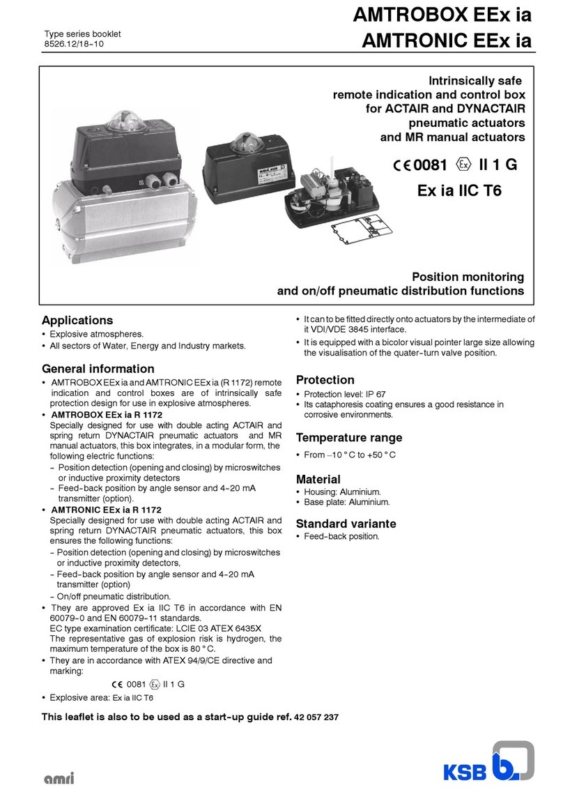
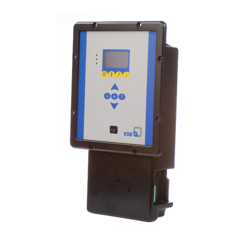
KSB DYNACTAIR 200 User manual

Maintenance
8519.83/3--EN DYNACTAIR 200 to 800 -- MAINTENANCE
INSTALLATION
MAINTENANCE
1 -- General overview
2 -- Recommended tools
3 -- Installation / Safety / Exhaust ports of springs cartridges
4 -- Adjustment of adjustable end stops
5 -- Actuator disassembly
6 -- Actuator re--assembly
7 -- Actuator / Valve coupling and protection
8 -- Trouble shooting
AMRI is ISO 9001 approved

DYNACTAIR 200 to 800 -- MAINTENANCE
2
1 -- GENERAL OVERVIEW
The purpose of this manual is to describe the installation / maintenance procedures and actions to be carried out in
case of breakdowns or faulty operations of DYNACTAIR 200 to 800 type pneumatic actuators.
Section A--A
DYNACTAIR 200 – Closure function by lack of control fluid
Section A--A
Parts included in the spare part kit
DYNACTAIR 400 and 800 – Closure function by lack of control fluid

DYNACTAIR 200 to 800 -- MAINTENANCE
3
Item Designation Item Designation
52--8 Protection sleeve 553.1 Thrust insert
59--40 Mandrel 553.2 Thrust insert
81--68 Pressure pad 554.1 Washer
88--5 Silencer 3/8” G 554.2 Washer
103 Housing 554.3 Washer
141 Cylinder 554.4 Washer
142 Cover 574.2 Rod
176 Cylinder head 593 Guiding strip
310.1 Self--lubricating bearing 598.1 Sub assembly springs cartridge
310.2 Self--lubricating strip 598.2 Sub assembly springs cartridge
310.3 Self--lubricating strip 726.1 Cylinder guiding flange
412.1 O--Ring 726.2 Cylinder guiding flange
412.2 O--Ring 893 Support plate
412.3 O--Ring 901.1 Hexagon head screw
412.4 O--Ring 901.2 Hexagon head screw
412.5 O--Ring 901.3 Hexagon head screw
412.6 O--Ring 904 Travel stop
412.7 O--Ring 914.1 Hexagon socket head screw
412.8 O--Ring 920.1 Operating nut
412.14 O--Ring 920.3 Hexagon nut
415.1 Lip seal ring 920.4 Hexagon nut
486.1 Ball 932.1 Spring retaining ring
970.1 Identity plate *
991 Grease 970.2 Safety instructions plate
* NOTE : The identity plate 970.1 indicates the actuator references. These are needed any requested for information
and spares.

DYNACTAIR 200 to 800 -- MAINTENANCE
4
Closure and opening functions by lack of control fluid of these actuators are defined following drawings thereafter:
DYNACTAIR 200 Closure function by lack of control fluid
Opening operation under fluid pressure Closing function under springs action
Actuator/Valve closed Actuator/Valve open Actuator/Valve open Actuator/Valve closed
DYNACTAIR 200 Opening function by lack of control fluid
Closing operation under fluid pressure Opening function under springs action
Actuator/Valve open Actuator/Valve closed Actuator/Valve closed Actuator/Valve open
DYNACTAIR 400 and 800 Closure function by lack of control fluid
Opening operation under fluid pressure
Actuator/Valve closed Actuator/Valve open
Closing operation under springs action
Actuator/Valve open Actuator/Valve closed
DYNACTAIR 400 and 800 Opening function by lack of control fluid
Closing operation under fluid pressure
Actuator/Valve open Actuator/Valve closed
Opening operation under springs action
Actuator/Valve closed Actuator/Valve open
During the operation under pressure, the actuator is maintened in position by the air supply.

DYNACTAIR 200 to 800 -- MAINTENANCE
5
2 -- RECOMMENDED TOOLS (not supplied)
-- Pneumatic screwing machine
-- Flat spanners 24 and 30
-- Allen key 8, 10 and 14
-- Screw driver
-- Mallet
-- 2 brushes for grease: the brushes must not loose its hair (one for cleaning out the old grease and one for greasing)
HANDLING MEANS (not supplied)
-- Handling means (crane, hoist, travelling crane, etc...)
-- Slings
CONSUMABLE
-- Grease Multis MS2 (Total) or RETINAX AM (Shell) or RENOLIT MO2 (Fuchs).
-- Specific grease may be used for special application.
Needed quantity of grease: 400 ml.
-- Iamsub Spalmatura mastic (Veneziani) or Sikaflex 227 or equivalent.
-- Glue Loctite 242 or equivalent.
-- Flange sealant Loctite 58--14 or 58--31, Omnifit FD30 or equivalent
-- KSB spare parts kits, according to the actuator size.
3 -- INSTALLATION -- SAFETY
3.1 -- Safety instruction
The user is responsible for ensuring that all maintenance, inspection and installation work is carried out by authorized,
adequately qualified staff who are thoroughly familiar with this manual.
Any work on an actuator may only be performed after the deconnecting pneumatic energy supply.
ATTENTION : this actuator contains strong compressed springs. The dismantling of the actuator must be careful.
3.2 -- Inadmissible modes of operation
Operational safety and reliability of the actuator supplied is only warranted for its designated use as defined in the
type series booklet.
The limits stated in the technical documentations must not be exceeded under any circumstances.
3.3 -- Before any action
-- Index the mounting position of the actuator onto the valve (Position N or M)
-- Index the position of the pointer 629 on mandrel 59--40
-- The disassembly of the actuator must be performed with be careful.
-- The device retrieval system stores mechanical energy (Cartridge springs 598.1 / 598.2), the dismantling of
this cartridge springs is strictly PROHIBITED.
-- If the maintenance of the spring cartridge (598.1 / 598.2) is necessary, it must be carried out by KSB Service.

DYNACTAIR 200 to 800 -- MAINTENANCE
6
3.4 -- Adaptation onto the valve
In case of thick paint on the valve, put washers to avoid the nut to damage the paint
The adaptation onto the valves is achieved either directly or through adaptors parts:
Interchangeable inserts manufactured
to the size and the shape of the different
shafts output
Flange sealant
FIGURE 1FIGURE 2
Direct fitting Adaptor flange fitting
Glued
Glued
Flange sealant
Adaptor flange
3.5 -- Actuator position onto the valve
If the open or closed position are not known, it is then necessary to apply air pressure in order to obtain clockwise
operation : then, the actuator is in a closed position.
The actuator can be mounted in four positions, at 90°intervals.
Standard arrangement is the N position 1
DYNACTAIR 200 to 800
Arrangement N Arrangement M
Position 1 Position 2 Position 1 Position 2
Flow direction -- Valve shown in closed position
The arrangement position can be modified at site following the procedure described below and the specific assembly
operations in accordance with maintenance procedure.

DYNACTAIR 200 to 800 -- MAINTENANCE
7
3.6 -- transformation
Arrangement N Arrangement M
-- Drop the air pressure to put the valve in safety position. In case of offset disc valve, drop the pressure in the pipe,
-- Disconnect the actuator from the valve,
-- Remove the pointer 629,
-- Remove the ball 486 out of the groove using a screwdriver, pin punch,...
-- Insert the ball 486 in the perpendicular groove,
-- Refit the position plate 970.2 (If any, in case of pointer or flag) at 90°from its initial position and retighten its screw,
-- Mount the pointer at 90°in the initial position,
-- Disengage mandrel insert, turn it 90°and reinsert into the mandrel (in the case of a flat ended shaft),
-- Clean the surface and use sealant paste.
-- Re--assemble the actuator onto the valve at 90°in the initial position.
Caution: If a limit switch box is fitted onto the actuator, the adjustments must be modified following the instructions
given in its user guide documents.
486
3.7 -- Exhaust ports of spring cartridges
These exhaust ports enable the “breathing” (outlet/inlet) of the spring cartridges.
They are protected by sintered silencers. If these silencers clog, this could be detrimental to the operation of the
actuator. It is advisable to remove and clean them.
In a damp or external environment, water could be drawn in during operation. It is strongly recommended to collect
the outlets (orifices 1/2” G) by piping towards a protected environment or downwards.

DYNACTAIR 200 to 800 -- MAINTENANCE
8
4 -- ADJUSTMENT OF STANDARD ADJUSTABLE END STOPS (±2°)
REMINDER :
These actuators are equipped with adjustable end stops only in the close position.
Adjustable end stops in open position are fixed and not adjustable.
Adjustable end stops are factory set and need no further adjustment at site.
This is of utmost importance for the perfect tightness of the valve.
After any intervention on the actuator, the correct adjustment of the adjustable end stops must be verified.
If need be, this adjustment could be modified as per the following procedure :
Adjustment to be carried out on the complete unit : valve + actuator
WARNING : Do not damage O--rings 412.4 while adjustment operations
DYNACTAIR 200
Closure function by lack of control fluid : adjustment of closure end stops
-- Put the unit in the open position by pressurising the actuator
-- Unscrew the 3 nuts 920.4
-- Progressively adjust in staggered way and with the same value
the 3 adjustable end stops (measure the overheight compared to
the cylinder head) until the required position is obtained by the
release of the chamber pressure
-- Repeat several times these operations if need be
-- Tighten the 3 nuts 920.4
Opening function by lack of control fluid : adjustment end stops in closure
-- Unscrew the nuts 920.3
-- Unscrew of a few turns 1 of the 2 adjustable end stops
-- Adjust the other adjustable end stop 904 until the required position is obtained by pressurising the chamber and
lock in position nut 920.3
-- Leave the unit under pressure
-- Adjust the second adjustable end stop until contact with the nut 920.1 then lock nut 920.3
DYNACTAIR 400 and 800
Closing or Opening function by lack of control fluid : adjustment end stops in closure
-- Put the unit in the open position by pressurising the actuator
-- Unscrew the 3 nuts 920.4
-- Progressively adjust in staggered way and with the same value the 3 adjustable end stops (measure the overheight
compared to the cylinder head) until the required position is obtained by the release of the chamber pressure
-- Repeat several times these operations if need be
-- Tighten the 3 nuts 920.4
WARNING :
-- Screw clockwise to decrease the valve closure
-- Screw anti--clockwise to increase the valve closure

DYNACTAIR 200 to 800 -- MAINTENANCE
9
5 -- ACTUATOR DISASSEMBLY
-- Identify both the pointer and the mounting position of the actuator onto the valve.
-- Drop the air pressure to put the valve in safety position. In case of offset disc valve, drop the pressure in the pipe.
-- Disconnect the air supply
-- Remove the actuator and the accessories from the valve and place them on a work bench-- Disconnect all
accessories from the actuator
-- Ensure that the actuator is not pressurised, no presence of air in either chamber should be detected
-- If the actuator has a pointer 629, remove the sub--unit plug 916 , screw 900 and pointer 629.
Unscrew 4 screws 901.1
Remove the cover 142, the O--ring
412.5, the self--lubricating strip 310.2
and the O--ring 412.7
5.1 -- Dismantling of cover 142
5.2 -- Dismantling of cylinder and piston o--rings
-- Before any action, index the cylinder mounting position,
the sides of the cylinder head 176 and the cylinder guiding
flange 726.1
WARNING : The cylinder mounting direction is not reversible.
-- Remove the 2 diametrically opposed screws 901.3 of the
cylinder head and the washers 554.4
Replace those 2 screws by capstan screws
-- Loosen by several turns the nuts 920.4
-- Identify (measure or index) the height of the overlength of
the adjustable end stops 553 compared to the cylinder
head 176

DYNACTAIR 200 to 800 -- MAINTENANCE
10
-- Housing side : unscrew the screws 901.3 on the cylinder guiding
flange 726.1 and remove the washers 554.4 and the support plates 893
-- Push the unit cylinder 141 + cylinder head 176 inwards the cylinder
and remove the spring retaining ring 932.1
-- Sling the unit cylinder/cylinder head with capstan screws
-- Remove carefully cylinder/cylinder head (heavy and cumbersome part) not to damage the inside and
put it on the work bench
-- Unscrew the screws 901.3 and remove the washers 554.4 on the cylinder head
-- Push the cylinder head 176 using capstan screws and remove the spring retaining ring 932.1
-- Remove the cylinder head 176 and remove the O--ring 412.1
-- Remove the O--ring 412.14 of the guiding flange of the spring cartridge
-- Remove the O--ring 412.14 and the guiding strip 593 on the piston
-- Remove the O--ring 412.1 on the cylinder guiding flange 726.1 on the cylinder
-- Dismantling procedure -- maintenance is limited to the operations previously described
CAUTION :
Thrust inserts 553.2 are fixed. No adjustment is necessary (complete screwing)
NOTE : Some actuators can be equipped with a 0.2mm thick wedge fitted under the guiding strip :
this wedge is to be left in place
-- Unscrew alternatively and in a staggered way, the adjustable end stops 553 until contact with the screw heads
is obtained
= release the pressure of the spring cartridge
REMINDER : The spring cartridge is made safe and reaches in auto--stop after a few turns of adjustable end
stops 553
The sub--unit cylinder head + spring cartridge (598.1 / 598.2)
is a device factory mounted and made safe (coupling nut welding).
It is strictly prohibited for safety reasons to
dismantle this sub--unit (598.1 / 598.2).
Handle carefully this sub--unit.
Keep it in a dry environment.
DYNACTAIR 200 : Protection sleeve side :
-- Unscrew the screws 901.2 and remove the support plates
893 and remove the sub--unit protection sleeve 52.8 and
remove the O--ring 412.3
-- Unscrew the nuts 920.3, remove the washers 554.2
and the O--rings 412.8
DYNACTAIR 400 and 800
Repeat these operations on the second cylinder
VOIR PARAGRAPH 3.3 “BEFORE ANY ACTION” page 4

DYNACTAIR 200 to 800 -- MAINTENANCE
11
6 -- ACTUATOR REASSEMBLY
6.1 -- Preparation of parts
All constitutive parts of the spare kits must be used.
O--rings and guiding strips must be lubricated with grease as defined in paragraph “consumables”, before being put
in place.
In the following pages, take off the old grease and clean the parts before greasing and re--assembly.
6.2 -- Kinematics greasing
Grease the nut 920.1 (where the pressure pads 81--68 slide), on the upper and lower sides.
For specific applications with considerable and frequent temperature changes, it is strongly recommended to brush with
the brush all the internal areas (gear casing, cap, cover, bottom, chuck, thrust washer, ...) with grease at least(200 ml).
Specific grease may also be used.

DYNACTAIR 200 to 800 -- MAINTENANCE
12
-- Ensure that cover is clean
-- Grease the housing of the guiding
strip 310.2 and set in place
-- Insert the greased O--ring 412.5
in the cover 142
-- Reinsert the greased O--ring 412.7.
in the upper part of the mandrel
6.3 -- Cover re--assembly
Carefully reassemble the cover.
Do not damage the O--rings and the
guiding strip.
If needed, finish the insertion using a
mallet and put back the 4 screws
901.1 in place

DYNACTAIR 200 to 800 -- MAINTENANCE
13
6.4 -- Cylinder re--assembly
-- When sufficiently inserted put in place the
spring retaining ring 932.1 located on the
kinematics side
-- Lift and remove the cylinder until contact retaining
ring 932 and the cylinder guiding flange 726.1
-- Clean carefully the interior of the cylinder 141
-- Caution :
Grease the interior of the cylinder 141
-- Put the support plates 893, washers 554--4 and screws 901.3 on the cylinder guiding flange 726.1 back
in place in their initial position,
Do not completely tighten the screws 901.3
-- Clean the piston and fit the piston O--ring 412.14 and the guiding
strip 593
-- Clean the side plate of the spring cartridge and put in place the O--ring 412.14
-- Clean the cylinder head 176 and insert the O--ring 412.1
-- Clean the cylinder guiding flange 726.1 and fit in the O--ring 412.1
-- Grease the O--rings, fill in the groove with grease and set in place
Special care :
Greasing O--rings before and after mounting is strongly recommended.
Do not use tools for the insertion of the O--rings in their groove.
-- For an easy assembly, it is advised to sling
the actuator by the housing and place the
cylinder in vertical position
-- Move the unit cautiously downwards inside the
cylinder respecting the initial assembly position
(take into consideration the initial indexing)

DYNACTAIR 200 to 800 -- MAINTENANCE
14
-- Place the cylinder head 176 back until contact with the retaining ring
is achieved and remove the capstan screws.
-- Unscrew alternatively and in a staggered way, the adjustable end
stops 553 till their initial position is obtained.
For an easier operation, it is recommended to connect
and supply the actuator to a 2 bar air pressure
-- Insert the greased O--rings 412.4, washers 554.1 on the adjustable
end stops 553 and tighten the nuts 920.4
Care should be taken not to damage the O--rings during this
operation.
-- Fit again the cylinder head 176, push it using the capstan
screws and insert the retaining ring 932.1
-- Disassemble the silencer(s) 88--5, carefully clean and put back in place
-- Connect air supplies and pressurise
Check tightness and the correct operation of the actuator
-- Place the actuator in horizontal position
-- Remove the nuts 920.4, washers 554.1 and O--rings 412.4, from the end adjustable stops 553
-- Fully tighten screws 901.3 on the guiding flange then those of the cylinder head
DYNACTAIR 400 and 800 : Repeat these operations on the second cylinder
DYNACTAIR 200 : Protection sleeve side
-- Put the O--ring 412.3 on the protection sleeve 52.8
-- Mount the greased O--rings 412.8 on screws 904, then the
washers 554.2 and tighten the nuts 920.3
-- Mount the protection sleeve 52--8 on the housing with the
support plates 893 and the screws 901.1.

DYNACTAIR 200 to 800 -- MAINTENANCE
15
7 -- ACTUATOR/VALVE COUPLING AND PROTECTION
It is Customer responsability to take care of the paint and to prevent rust.
7.1 -- Protection
-- Outside space in front of the spring retaining rings 932--1:
It is compulsory to clean with a dry rag and to fill this gap with Sikaflex 227 for standard application, or with
Iamsub Spalmatura mastic (Veneziani) for application in corrosive ambiant.
-- Clean, degrease and paint all the surfaces, all the contact junctions in order to prevent rust.
The paint must be chosen according to the environment.
7.2 -- Coupling
Fit the pointer 629 and/or the accessories on the actuator in their initial position.
DIRECTFITTINGfollowingfigure1§3
Put some drops of glue on the threads of tie--bolts and screw
Cover all the area of the base plate Actuator / Valve with flange sealant
or
ADAPTORFLANGEFITTINGfollowingfigure2§3
Actuator side, cover all the area of the base plate Actuator / Valve with flange sealant
Fit the flange onto the actuator
Put some drops of glue on the threads of screws and screw them
Put some drops of glue on the threads of tie--bolts and screw them
Valve side, cover all the area of the base plate Actuator / Valve with flange sealant
For a better protection of the actuator, it is recommended to clean, dry and paint all the interfaces after fitting
(interfaces gear casing / bottom, gear casing / cover and gear casing / cap).
-- Couple the actuator onto the valve in its initial position,
-- Check the correct operation of the unit Valve / Actuator / Accessories.
--Ifnecessary,re--adjusttheadjustableendstops:see§4Adjustmentofclosingadjustableendstops.

KSB S.A.S.
4, allée des Barbanniers 92635 Gennevilliers Cedex (France)
Tel.:+33141477500Fax:+33141477510www.ksb.com
DYNACTAIR 200 to 800
8 -- TROUBLE SHOOTING
At cylinder head 176
Axial at pistons (of sub--unit 598) External leakage
At cylinder guiding flanges 726.1 / 726.2
No operation
Incomplete operation or stroke
Irregular operation
Reverse operation
Drifting of the actuator
Reverse or incorrect iIndication
Coupling impossible valve side
Coupling impossible accessories side
Damaged O--rings 412.1 and 412.4 Change O--rings 412.1 and 412.4
Damaged O--rings 412.14 Change O--ring 412.14
Damaged O--rings 412.1 Change O--rings 412.1
Absence or insufficient pressure Check solenoîd, restrictors, pressure
and connections
Valve blocked Check the valve and/or the interface
with pipe
Internal leakage Change O--rings 412.14
External leakage See external leakage
Rupture of internal coumponents Consult the manufacturer for technical
advice
Wrong actuator selection Consult technical leaflet Nr 8511
Consult valve technical leaflet
Override in operation Release air pressure
Lock the override
Consult technical leaflet Nr 8511
If AMTRONIC: possible presence of screws
904
Uncouple the AMTRONIC
Remove screws 904
Wrong end stops adjustment Refer to § adjustment of adjustable end
stops
AMTRONIC positioner maladjusted Consult technical leaflet Nr 2316
Valve overtorque Contact the manufacturer
Wrong interface Check the driving and/or adapter
flanges.
Consult DYNACTAIR technical leaflet
Nr 8511 or contact the manufacturer
Air flow too low or silencers clogged Check solenoïd, restrictors, pressure
and connections and passage section
of air pressure
Closed actuator / Valve open
or closed valve / Actuator open
Place the valve and the actuator in the
same position
Inverted pneumatic connections Check the pneumatic connection
Wrong definition of the solenoïd Check the defintion of the solenoïds
Wrong assembly of the actuator onto the valve Check arrangement positions on
DYNACTAIR technical leaflet Nr 8511
Pressure non constant Pressurise the equipment and keep it
under pressure
Internal or external leakage with flow control
equipment + AMTRONIC or varying input
signal
See Internal or external leakage
Check the O--ring of the mounting plate
between DYNACTAIR and AMTRONIC
Wrong adjustment of limit switch cams Check the adjustment according to
AMTRONIC technical leaflet Nr 2316
Control and remote indication non compatible Check accessories technical leaflet
concerned
05.10.2015 This leaflet is not contractual.
and may be amended without notice
8519.83/3--EN
This manual suits for next models
2
Table of contents
Other KSB Controllers manuals
Popular Controllers manuals by other brands

Lynxspring
Lynxspring JENEsys Edge 414 installation guide

Acolyte
Acolyte DMXCTRL installation guide

Emerson
Emerson Bettis M Series Installation, operation and maintenance manual

Hedy
Hedy HD700 Series Easy start guide

ETC
ETC Echoflex ELED3 Configuration guide

TDI
TDI T100-V Installation and operating manual