KSB 4STQ Series Installation instructions

KSB Mechanical Seal
4STQ
Installation/Operating Manual

Legal information/Copyright
Installation/Operating Manual 4STQ
Original operating manual
All rights reserved. The contents provided herein must neither be distributed, copied, reproduced,
edited or processed for any other purpose, nor otherwise transmitted, published or made available to a
third party without the manufacturer's express written consent.
Subject to technical modification without prior notice.
© KSB SE & Co. KGaA, Frankenthal 16/04/2020

Contents
3 of 44
4STQ
Contents
1 General.................................................................................................................................................... 5
1.1 Principles ...........................................................................................................................................................5
1.2 Target group.....................................................................................................................................................5
1.3 Other applicable documents............................................................................................................................5
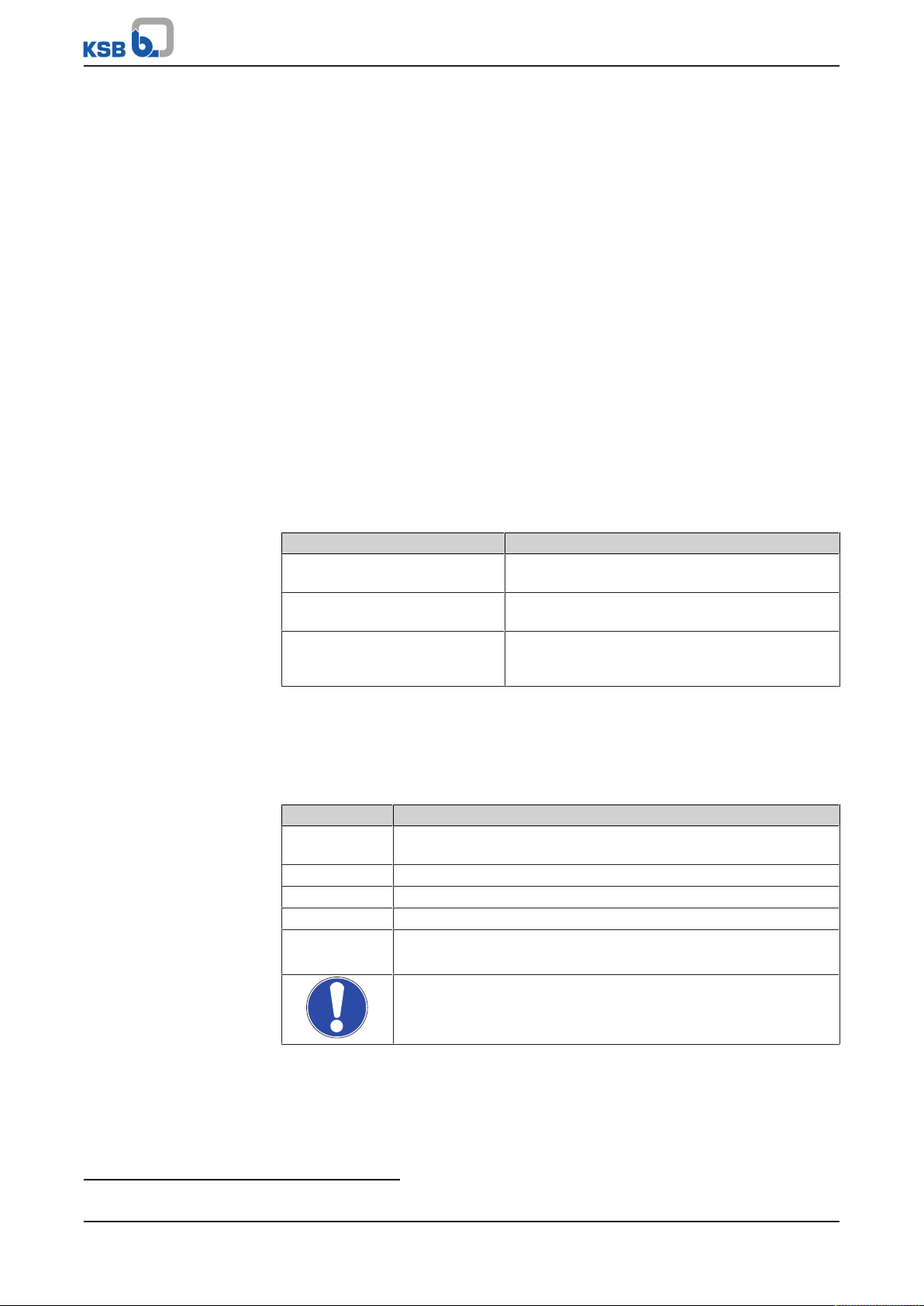
1.4 Symbols .............................................................................................................................................................5
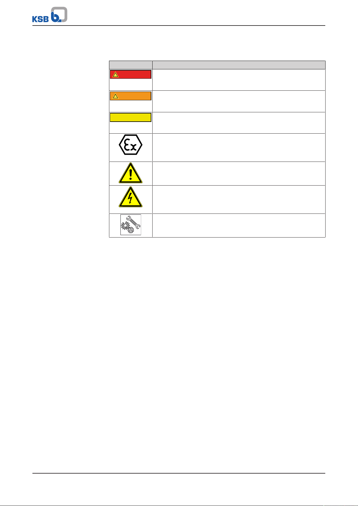
1.5 Key to safety symbols/markings.......................................................................................................................6
2 Safety...................................................................................................................................................... 7
2.1 General..............................................................................................................................................................7
2.2 Intended use .....................................................................................................................................................7
2.3 Personnel qualification and training...............................................................................................................7
2.4 Consequences and risks caused by non-compliance with this manual .........................................................7
2.5 Safety awareness ..............................................................................................................................................8
2.6 Safety information for the user/operator.......................................................................................................8
2.7 Safety information for maintenance, inspection and installation ................................................................8
2.8 Unauthorised modes of operation..................................................................................................................8
3 Transport/Storage/Disposal .................................................................................................................. 9
3.1 Checking the condition upon delivery............................................................................................................9
3.2 Transport...........................................................................................................................................................9
3.3 Storage/preservation........................................................................................................................................9
3.4 Return to supplier...........................................................................................................................................10
3.5 Disposal ...........................................................................................................................................................11
4 Description............................................................................................................................................ 12
4.1 General description ........................................................................................................................................12
4.2 Designation.....................................................................................................................................................12
4.3 Materials .........................................................................................................................................................12
4.4 Design details..................................................................................................................................................12
4.5 Configuration and function...........................................................................................................................13
5 Installation/Dismantling...................................................................................................................... 14
5.1 Permissible aids...............................................................................................................................................14
5.2 Prerequisites....................................................................................................................................................14
5.3 Installing the mechanical seal........................................................................................................................16
5.3.1 Installing the C022/025M1-4STQ and C033/033M1-4STQ double cartridge seals ..........................16
5.3.2 Installing the C033/055M1-4STQ double cartridge seal...................................................................18
5.3.3 Installing the double cartridge seal C055/065M1-4STQT.................................................................21
5.3.4 Installing the double cartridge seal C055/065M1-4STQ...................................................................22
5.3.5 Installing the double cartridge seal C120/120M1-4STQ...................................................................23
5.3.6 Installing the double cartridge seal C150/160M1-4STQ...................................................................24
5.3.7 Installing the double cartridge seal C190/190M1-4STQ...................................................................25
5.4 Removing the mechanical seal ......................................................................................................................26
5.4.1 Removing the C022/025M1-4STQ and C033/033M1-4STQ double cartridge seals .........................26
5.4.2 Removing the C033/055M1-4STQ double cartridge seal .................................................................26
5.4.3 Removing the C055/065M1-4STQT double cartridge seal ...............................................................26
5.4.4 Removing the C055/065M1-4STQ double cartridge seal .................................................................28
5.4.5 Removing the C120/120M1-4STQ double cartridge seal .................................................................28
5.4.6 Removing the C150/160M1-4STQ double cartridge seal .................................................................29
5.4.7 Removing the C190/190M1-4STQ double cartridge seal .................................................................29
6 Operation.............................................................................................................................................. 30
6.1 Safety instructions for operation...................................................................................................................30
6.2 Emissions .........................................................................................................................................................30
6.3 Operating limits..............................................................................................................................................31
7 Maintenance......................................................................................................................................... 32
7.1 Maintenance/inspection.................................................................................................................................32

Contents
4 of 44 4STQ
8 Trouble-shooting.................................................................................................................................. 33
9 Related Documents.............................................................................................................................. 34
9.1 General assembly drawings with list of components...................................................................................34
9.1.1 Cartridge seal C022/025M1-4STQ......................................................................................................34
9.1.2 Cartridge seal C033/033M1-4STQ......................................................................................................35
9.1.3 Cartridge seal C033/055M1-4STQ......................................................................................................36
9.1.4 Cartridge seal C055/065M1-4STQT....................................................................................................37
9.1.5 Cartridge seal C055/065M1-4STQ......................................................................................................38
9.1.6 Cartridge seal C120/120M1-4STQ......................................................................................................39
9.1.7 Cartridge seal C150/160M1-4STQ......................................................................................................40
9.1.8 Cartridge seal C190/190M1-4STQ......................................................................................................41
10 Certificate of Decontamination........................................................................................................... 42

1 General
5 of 44
4STQ
2580.821/04-EN
1 General
1.1 Principles
This operating manual is valid for the type series and variants indicated on the front
cover.
The operating manual describes the proper and safe use of this equipment in all
phases of operation.
The order number and order item number of the pump clearly identify the
mechanical seal via the corresponding material number in the pump's parts list and
serve as identification for all further business processes.
In the event of damage, immediately contact your nearest KSB Service centre to
maintain the right to claim under warranty.
For any queries: [email protected]
1.2 Target group
This operating manual is aimed at the target group of trained and qualified specialist
technical personnel.
1.3 Other applicable documents
Table1: Overview of other applicable documents
Document Contents
Data sheet Description of the technical data of the pump (set)
in which the mechanical seal is installed.
General assembly drawing1) Description of the mechanical seal as part of the
sectional drawing of the pump
Sub-supplier product literature1) Operating manuals and other product literature
describing accessories and integrated machinery
components
For accessories and/or integrated machinery components, observe the relevant
manufacturer's product literature.
1.4 Symbols
Table2: Symbols used in this manual
Symbol Description
✓Conditions which need to be fulfilled before proceeding with the
step-by-step instructions
⊳Safety instructions
⇨Result of an action
⇨Cross-references
1.
2.
Step-by-step instructions
Note
Recommendations and important information on how to handle
the product
1) If agreed to be included in the scope of supply

1 General
6 of 44 4STQ
2580.821/04-EN
1.5 Key to safety symbols/markings
Table3: Definition of safety symbols/markings
Symbol Description
!DANGER
DANGER
This signal word indicates a high-risk hazard which, if not avoided,
will result in death or serious injury.
!WARNING
WARNING
This signal word indicates a medium-risk hazard which, if not
avoided, could result in death or serious injury.
CAUTION
CAUTION
This signal word indicates a hazard which, if not avoided, could
result in damage to the machine and its functions.
Explosion protection
This symbol identifies information about avoiding explosions in
potentially explosive atmospheres in accordance with EU Directive
2014/34/EU (ATEX).
General hazard
In conjunction with one of the signal words this symbol indicates a
hazard which will or could result in death or serious injury.
Electrical hazard
In conjunction with one of the signal words this symbol indicates a
hazard involving electrical voltage and identifies information about
protection against electrical voltage.
Machine damage
In conjunction with the signal word CAUTION this symbol indicates
a hazard for the machine and its functions.

2 Safety
7 of 44
4STQ
2580.821/04-EN
2 Safety
!DANGER
All the information contained in this section refers to hazardous situations.
In addition to the present general safety information the action-related safety
information given in the other sections must be observed.
2.1 General
▪This operating manual contains general installation, operating and maintenance
instructions that must be observed to ensure safe operation of the system and
prevent personal injury and damage to property.
▪Comply with all the safety instructions given in the individual sections of this
operating manual.
▪The operating manual must be read and understood by the responsible specialist
personnel/operators prior to installation and commissioning.
▪The contents of this operating manual must be available to the specialist
personnel at the site at all times.
▪Information and markings attached directly to the product must always be
complied with and kept in a perfectly legible condition at all times. This applies
to, for example:
– Arrow indicating the direction of rotation
– Markings for connections
– Fitting direction
▪The operator is responsible for ensuring compliance with all local regulations not
taken into account.
2.2 Intended use
▪This product must only be operated within the limit values stated in the technical
product literature for the ambient temperature, fluid handled, speed, density,
pressure, temperature and in compliance with any other instructions provided in
the operating manual or other applicable documents.
▪The product must not be used in potentially explosive atmospheres.
2.3 Personnel qualification and training
▪ All personnel involved must be fully qualified to install, operate, maintain and
inspect the product this manual refers to.
▪The responsibilities, competence and supervision of all personnel involved in
transport, installation, operation, maintenance and inspection must be clearly
defined by the operator.
▪Deficits in knowledge must be rectified by means of training and instruction
provided by sufficiently trained specialist personnel. If required, the operator can
commission the manufacturer/supplier to train the personnel.
▪ Training on the product must always be supervised by specialist technical
personnel.
2.4 Consequences and risks caused by non-compliance with this manual
▪Non-compliance with these operating instructions will lead to forfeiture of
warranty cover and of any and all rights to claims for damages.
▪Non-compliance can, for example, have the following consequences:
– Hazards to persons due to electrical, thermal, mechanical and chemical
effects and explosions
– Failure of important product functions
– Failure of prescribed maintenance and servicing practices
– Hazard to the environment due to leakage of hazardous substances

2 Safety
8 of 44 4STQ
2580.821/04-EN
2.5 Safety awareness
In addition to the safety information contained in this operating manual and the
intended use, the following safety regulations shall be complied with:
▪Accident prevention, health regulations and safety regulations
▪Explosion protection regulations
▪Safety regulations for handling hazardous substances
▪Applicable standards, directives and laws
2.6 Safety information for the user/operator
▪Fit protective equipment (e.g. contact guards) supplied by the operator for hot,
cold or moving parts, and check that the equipment functions properly.
▪Do not remove any protective equipment (e.g. contact guards) during operation.
▪Provide the personnel with protective equipment and make sure it is used.
▪Contain leakages of hazardous fluids (e.g. explosive, toxic, hot) so as to avoid any
danger to persons and the environment. Observe all legal requirements.
▪The design of mechanical seals always produces a small amount of leakage.
▪Higher leakage may occur especially in the running-in phase. The leakage must
be drained off in a controlled way
2.7 Safety information for maintenance, inspection and installation
▪Modifications or alterations of the mechanical seal require the manufacturer's
prior consent.
▪Use only original spare parts or parts/components authorised by the
manufacturer. The use of other parts/components can invalidate any liability of
the manufacturer for resulting damage.
▪The operator ensures that maintenance, inspection and installation are
performed by authorised, qualified specialist personnel who are thoroughly
familiar with the manual.
▪Only carry out work on the mechanical seal when the shaft is not rotating.
For mechanical seals installed in pump sets:
▪The pump (set) must have cooled down to ambient temperature.
▪Pump pressure must have been released and the pump must have been drained.
▪When taking the pump set out of service always adhere to the procedure
described in the manual.
▪Decontaminate pumps which handle fluids posing a health hazard.
▪As soon as the work has been completed, re-install and re-activate any safety-
relevant devices and protective devices. Before returning the product to service,
observe all instructions on commissioning.
▪Observe the relevant sections of the corresponding pump operating manual.
2.8 Unauthorised modes of operation
Never operate the mechanical seal outside the limits stated in the data sheet and in
this operating manual.
The warranty relating to the operating reliability and safety of the mechanical seal
supplied is only valid if the mechanical seal is used in accordance with its intended
use.
Any damage caused by dry running shall be excluded from the warranty.

3 Transport/Storage/Disposal
9 of 44
4STQ
2580.821/04-EN
3 Transport/Storage/Disposal
3.1 Checking the condition upon delivery
1. On transfer of goods, check each packaging unit for damage.
2. In the event of in-transit damage, assess the exact damage, document it and
notify KSB or the supplying dealer and the insurer about the damage in writing
immediately.
3.2 Transport
CAUTION
Improper transport
Damage to the mechanical seal!
▷Only transport the mechanical seal in suitable packaging.
▷Observe the weights, symbols and instructions indicated on the packaging.
▷Use suitable, approved lifting accessories.
KSB’s standard packaging is suitable for dry transport ,e.g. by truck, rail, air. Special
packaging can be provided if specified in the contractual agreement.
CAUTION
Removing transport locks too early
Damage to previously locked components during transport!
▷If transport locks are fitted, do not remove them too early.
3.3 Storage/preservation
CAUTION
Improper storage
Damage due to humidity, vermin, corrosion and contamination!
▷Avoid outdoor storage.
▷Observe, check and record the storage conditions.
▷Regularly check the packaging for any damage.
▷Regularly check the humidity indicator of shrink-wrapped objects. (The relative
humidity should be <50%.)
▷If the relative humidity indicated for shrink-wrapped objects >50%, have the
equipment checked and repacked by the manufacturer.
CAUTION
Improper storage
Impairment of O-rings' sealing function!
▷Do not store O-rings together with chemicals, solvents, fuels, acids, etc.
▷Protect O-rings from light, in particular from direct sun exposure and strong
artificial light high in ultraviolet rays.
▷Check the O-rings for damage before they are fitted.

3 Transport/Storage/Disposal
10 of 44 4STQ
2580.821/04-EN
CAUTION
Wet, contaminated or damaged openings and connections
Damage to the mechanical seal!
Risk of embrittlement! Damage to elastomers!
▷Only open screw plugs and connections at the mechanical seal at the time of
installation.
▷Avoid opening screw plugs, connections and similar before that time.
We recommend taking the following measures for storing the mechanical seal:
For storing the mechanical seal observe standards ISO2230 and DIN7716.
Store the mechanical seal in its original packaging, placed on a level surface in a dry,
protected room with constant conditions that meet the following requirements:
▪Relative humidity <65%
▪Temperature between 15°C and 25°C
▪Moderately vented atmosphere
▪Dust-free and vermin-free
If properly stored indoors, the equipment is protected for a maximum of 36months.
New mechanical seals are supplied by our factory duly prepared for storage.
3.4 Return to supplier
1. Remove the used mechanical seal from the system.
2. Always flush and clean the mechanical seal, particularly if it has been used for
handling noxious, explosive, hot or other hazardous fluids.
3. If the mechanical seal has handled fluids whose residues could lead to corrosion
damage in the presence of atmospheric humidity or could ignite upon contact
with oxygen, the mechanical seal must also be neutralised and dried with
anhydrous inert gas.
4. Always complete and enclose a certificate of decontamination when returning
the mechanical seal. Always indicate any safety measures and decontamination
measures taken.
NOTE
If required, a blank certificate of decontamination can be downloaded from the
following web site: www.ksb.com/certificate_of_decontamination

3 Transport/Storage/Disposal
11 of 44
4STQ
2580.821/04-EN
3.5 Disposal
WARNING
Fluids handled, consumables and supplies which are hot and/or pose a health
hazard
Hazard to persons and the environment!
▷Collect and properly dispose of flushing fluid and any fluid residues.
▷Wear safety clothing and a protective mask if required.
▷Observe all legal regulations on the disposal of fluids posing a health hazard.
1. Dismantle the mechanical seal.
Collect greases and other lubricants during dismantling.
2. Separate and sort the mechanical seal materials, e.g. by:
- Metals
- Plastics
- Greases and other lubricants
3. Dispose of materials in accordance with local regulations or in another
controlled manner.

4 Description
12 of 44 4STQ
2580.821/04-EN
4 Description
4.1 General description
▪KSB mechanical seal
Mechanical seal for installation in pump sets and other rotating machinery in
accordance with the manufacturer's instructions.
4.2 Designation
Example: C120/120M1-4STQ
Table4: Designation key
Code Description
C Design
C Cartridge seal
120/120 Nominal diameter
M Direction of rotation
M Bi-directional with multi-spring arrangement
S Bi-directional with single spring
L Direction of rotation anti-clockwise
R Direction of rotation clockwise
1 Anti-twist lock of mating ring
0 Without lock
1 With lock
4STQ Type series
4.3 Materials
▪Depending on the application
▪See product literature of the pump
▪Selection of suitable material variant on request
4.4 Design details
Design
▪Cartridge seal
▪Double seal arrangement
▪Suitable for non-pressurised buffer fluid in acc. with API Plan52
▪Bi-directional
▪Axial movability depending on the size (ðSection6.3,Page31)
▪Multi-spring arrangement

4 Description
13 of 44
4STQ
2580.821/04-EN
4.5 Configuration and function
1
2
3 4 5
6
7
8
9
11
13
14
15
10
12
16
19
17
18
Fig.1: Sectional drawing
Design Mechanical seal for installation in pump sets and other rotating machinery in
accordance with the manufacturer's instructions.
KSB’s mechanical seal 4STQ is a cartridge seal that has been especially developed for
use in pumps of the Sewatec, Sewabloc and AmarexKRT type series. KSB’s
mechanical seal 4STQ can only be operated with a non-pressurised buffer fluid. It is a
double mechanical seal. Its inboard seal is designed with an axially moveable primary
ring 4 and a mating ring 3, its outboard seal with an axially moveable primary ring 8
and a mating ring 7. The inboard seal provides sealing on the product side, the
outboard seal on the atmosphere side.
Function The inboard seal and outboard seal are stationary seals with a rotating mating ring 7.
The rotating rings are in contact with the stationary primary rings 4 and 8 and form a
sealing clearance. The springs 15 and 11 press the primary ring against the mating
ring. They ensure that the seal faces stay in contact with each other also during
unpressurised operation. The O-rings 12 and 18 provide sealing between the primary
rings/ mating rings and the housing parts. The O-rings 17, 16 and 10 provide sealing
between the seal cartridge and the pump casing. The O-ring 19 provides sealing
between the cartridge and the shaft. The O-ring 13 provides sealing between the
mating ring carrier 6 and the shaft sleeve 1. Torque transmission from the shaft to
the shaft sleeve is effected by the key. The parallel pins 2 and 14 as well as the thrust
rings 5 and 9 ensure transmission of the torque from the primary rings and mating
rings to the housing parts.
To prevent dry running of the outboard seal, the pressure of the buffer fluid applied
to the seal must equal the ambient pressure as a minimum. The space between the
inboard seal and the outboard seal must be completely filled with this fluid and
vented.

5 Installation/Dismantling
14 of 44 4STQ
2580.821/04-EN
5 Installation/Dismantling
NOTE
Priority shall be given to the installation instructions and/or installation sequence in
the documents of the pump set into which this mechanical seal is to be installed.
This also applies to the dismantling instructions and/or dismantling sequence.
5.1 Permissible aids
CAUTION
Impermissible cleaning agents
Damage to the seal faces at the mechanical seal!
▷For removing minor contamination use only paper tissues and ethyl alcohol.
▷Do not use dirty cleaning cloths or cleaning cloths that leave behind lint.
CAUTION
Impermissible assembly aids
Sealing elements made of ethylene propylene diene rubber perishing or swelling
up!
▷Never let sealing elements come into contact with mineral oil base lubricants.
▷Use permissible lubricants only.
▷Verify that the assembly aids are silicon-free.
▪Lubricants2)
– Permanent lubricants, such as non-mineral grease (Klüber AsonicHQ72-102)
are used for elastomers that do not serve to transmit the torque. Examples
are mating rings with an anti-twist lock or primary rings that move axially
relative to the pump components.
– Non-permanent lubricants such as a soap solution, for example, are used for
elastomers that serve as a sealing element and, in addition, transmit the
torque. An example would be a mating ring without anti-twist lock.
▪Recommended cleaning agent for seal faces and grub screws: ethyl alcohol
▪Thread-locking agent: Loctite, No. 243
▪Open-ended wrench, ring spanner, socket wrench (cleaned, no impact tools)
▪Torque wrench (cleaned)
5.2 Prerequisites
▪Shaft run-out to ISO5199:
– For shaft diameter ≤50mm: 0.05mm max.
– For shaft diameter 50 to 100mm: 0.08mm max.
– For shaft diameter >100mm: 0.10mm max.
▪Face run-out of the shaft in relation to the vertical connection surface of the
casing:
– For shaft speed ≤750rpm: 0.2mm max.
– For shaft speed >750rpm to 1000rpm: 0.15mm max.
– For shaft speed >1000rpm to 1500rpm: 0.08mm max.
– For shaft speed >1500rpm to 3000rpm: 0.025mm max.
▪The seal faces are clean and have not been touched with fingers.
2) Lubricants must be compatible with all fluids used. They must not be aggressive to the secondary sealing elements.

5 Installation/Dismantling
15 of 44
4STQ
2580.821/04-EN
▪The mechanical seal is in proper condition and complete.
▪The elastomers are free from any contamination, cracks, softening, hardening,
stickiness and discolouration.
▪The mechanical seal has been placed down on a clean and level surface.

5 Installation/Dismantling
16 of 44 4STQ
2580.821/04-EN
5.3 Installing the mechanical seal
5.3.1 Installing the C022/025M1-4STQ and C033/033M1-4STQ double cartridge seals
CAUTION
Use of grease or other permanent lubricants
Torque transmission impeded/ overheating of and damage to the pump!
▷Never use grease or other permanent lubricants for fitting the torque-
transmitting elements of a mechanical seal.
▷Use soft soap to reduce any friction caused during assembly.
▷Never coat the mechanical seal faces with grease or oil.
CAUTION
Improper installation of the mechanical seal
Damage to the seal faces!
▷Install the mechanical seal using the supplied mounting device 101-47.
▷Prevent sudden forces acting on the mounting device and mechanical seal.
üThe relevant documentation for installing the mechanical seal is observed.
(ðSection9.1.1,Page34) (ðSection9.1.2,Page35)
üThe back pull-out unit has been removed from the pump casing and safely
positioned and secured in a horizontal position.
üThe original 4STQ cartridge seal is fully assembled and undamaged.
üMounting device 101-47 is available.
1. Insert circlip 932.59 in the shaft groove and make sure that circlip 932.59 is
positioned correctly in the shaft groove. When fitting the circlip take care to
prevent damage to the shaft.
2. Prior to assembly, wet the external elastomers (O-rings and gasket) and the
seats of the mechanical seal at the shaft, discharge cover 163 and seal housing
with a suitable lubricant (e.g. soap solution).
3. Press mechanical seal 433 into discharge cover 163 by hand as far as possible.
101-47
433
Fig.2: Mounting device 101-47

5 Installation/Dismantling
17 of 44
4STQ
2580.821/04-EN
K
Fig.3: Reference dimension "K” from shaft end to mechanical seal
4. Fit mechanical seal 433 using mounting device 101-47. Check the mechanical
seal position against reference dimension "K" (see table: Reference dimension
"K") and correct the installation position if required.
5. Slide O-ring 412.58 over the shaft until it abuts against the mechanical seal.
Table5: Reference dimension "K"
Size Impeller type Reference dimension
"K"
[mm]
40-252 F, K, S 39 +/- 0,5
50-215 F 25 +/- 0,5
50-216 F, S 25 +/- 0,5
65-215 F 25 +/- 0,5
65-216 E 33 +/- 0,5
65-217 F 25 +/- 0,5
65-253 K 43 +/- 0,5
80-215 F 25 +/- 0,5
80-216 E 33 +/- 0,5
80-216 F 25 +/- 0,5
80-252 F 39 +/- 0,5
80-253 E, F, K 43 +/- 0,5
80-315 D, K 43 +/- 0,5
80-317 D, F 43 +/- 0,5
100-215 F 25 +/- 0,5
100-253 D, E, K 43 +/- 0,5
100-254 F, K 39 +/- 0,5
100-315 D, E, F, K 43 +/- 0,5
100-316 D, F, K 43 +/- 0,5
100-317 E 43 +/- 0,5
150-253 D 43 +/- 0,5
150-315 D, F 43 +/- 0,5
150-317 E, K 43 +/- 0,5
200-315 D, K 43 +/- 0,5
200-316 K 43 +/- 0,5
200-317 K 43 +/- 0,5
200-318 K 43 +/- 0,5

5 Installation/Dismantling
18 of 44 4STQ
2580.821/04-EN
5.3.2 Installing the C033/055M1-4STQ double cartridge seal
WARNING
Components with sharp edges
Risk of cutting or shearing injuries!
▷Always use appropriate caution for installation and dismantling work.
▷Wear work gloves.
CAUTION
Use of grease or other permanent lubricants
Torque transmission impeded/ overheating of and damage to the pump!
▷Never use grease or other permanent lubricants for fitting the torque-
transmitting elements of a mechanical seal.
▷Use soft soap to reduce any friction caused during assembly.
▷Never coat the mechanical seal faces with grease or oil.
CAUTION
Improper installation of the mechanical seal
Damage to the seal faces!
▷Install the mechanical seal using the supplied mounting device C.
▷Prevent sudden forces acting on the mounting device and mechanical seal.
üThe relevant documentation for installing the mechanical seal is observed.
(ðSection9.1.3,Page36)
üThe back pull-out unit has been removed from the pump casing and safely
positioned and secured in a horizontal position.
üThe original 4STQ cartridge seal is fully assembled and undamaged.
üMounting device C is available.
1. Guide the mechanical seal (without external O-rings) onto the shaft as far as it
will go.
A
1
Fig.4: Illustration of the groove
2. Visually check that the groove for the circlip in discharge cover1 aligns with the
corresponding surface of the mechanical seal (seal housing).
3. Pull the mechanical seal off the shaft.
4. Fit the circlip in the shaft groove.

5 Installation/Dismantling
19 of 44
4STQ
2580.821/04-EN
B
A
Fig.5: Marking the shaft end
5. Mark the front face of shaft endA. To do so extend the central position of ring
openingB in the axial direction.
A
B
Fig.6: Marking the mechanical seal
6. Mark the front face of mechanical sealA. To do so extend the position of the
anti-rotation pinB in the axial direction.
7. Fit the external O-rings and wet them with a suitable lubricant (e.g. soap
solution).
A
Fig.7: Aligning the markings

5 Installation/Dismantling
20 of 44 4STQ
2580.821/04-EN
8. Place the mechanical seal on the shaft. Guide it as far into the discharge cover as
possible. Verify that the markingsA are aligned with each other.
C
Fig.8: Mounting device C
K
Fig.9: Reference dimension "K” from shaft end to mechanical seal
9. Position mounting device C on the front face of the mechanical seal. Fit the
mechanical seal. Verify the position of the mechanical seal with reference
dimension “K” = 43+/- 0.5mm; adjust the position if necessary.
932
412
163
Fig.10: Final assembly
This manual suits for next models
8
Table of contents