KSB Delta Solo SVP Installation instructions

Pressure Booster System
KSBDeltaSolo /
KSBDeltaEco
KSB Delta Solo SVP
KSB Delta Eco SVP
Installation/Operating Manual

Legal information/Copyright
Installation/Operating Manual KSBDeltaSolo / KSBDeltaEco
Original operating manual
All rights reserved. The contents provided herein must neither be distributed, copied, reproduced,
edited or processed for any other purpose, nor otherwise transmitted, published or made available to a
third party without the manufacturer's express written consent.
Subject to technical modification without prior notice.
© KSB B.V., Alphen aan den Rijn, Nederland 13/09/2018

Contents
3 of 68
KSBDeltaSolo / KSBDeltaEco
Contents
Glossary .................................................................................................................................................. 5
1 General.................................................................................................................................................... 6
1.1 Principles ...........................................................................................................................................................6
1.2 Installation of partly completed machinery....................................................................................................6
1.3 Target group.....................................................................................................................................................6
1.4 Other applicable documents............................................................................................................................6
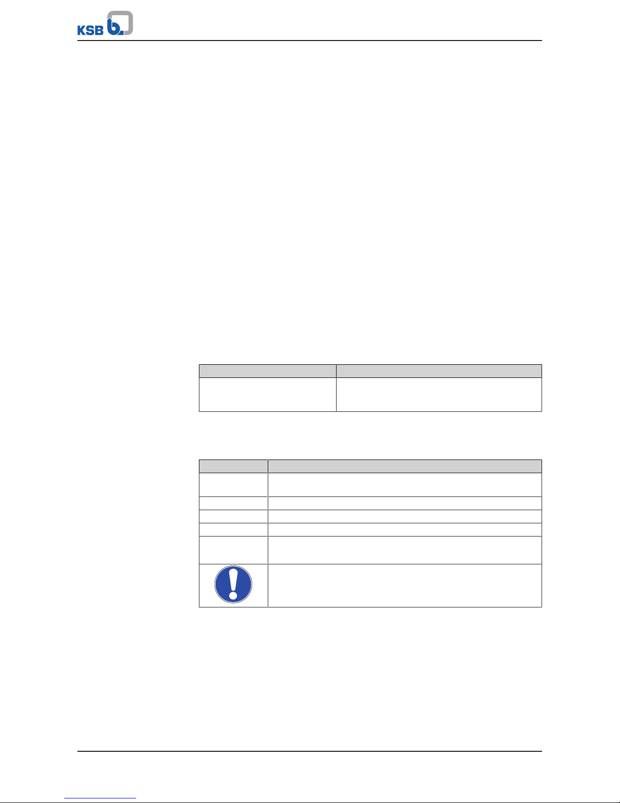
1.5 Symbols .............................................................................................................................................................6
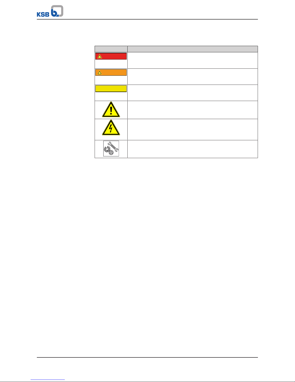
1.6 Key to safety symbols/markings.......................................................................................................................7
2 Safety...................................................................................................................................................... 8
2.1 General..............................................................................................................................................................8
2.2 Intended use .....................................................................................................................................................8
2.2.1 Prevention of foreseeable misuse.......................................................................................................8
2.3 Personnel qualification and personnel training.............................................................................................8
2.4 Consequences and risks caused by non-compliance with this manual .........................................................9
2.5 Safety awareness ..............................................................................................................................................9
2.6 Safety information for the operator/user.......................................................................................................9
2.7 Safety information for maintenance, inspection and installation ................................................................9
2.8 Unauthorised modes of operation................................................................................................................10
2.9 Electromagnetic compatibility (EMC)............................................................................................................10
2.9.1 Interference emission requirements .................................................................................................10
2.9.2 Line harmonics requirements............................................................................................................11
2.9.3 Interference immunity requirements ...............................................................................................11
3 Software Changes................................................................................................................................ 12
4 Transport/Temporary Storage/Disposal............................................................................................. 13
4.1 Checking the condition upon delivery..........................................................................................................13
4.2 Transport.........................................................................................................................................................13
4.3 Storage/preservation......................................................................................................................................13
4.4 Return to supplier ..........................................................................................................................................14
4.5 Disposal ...........................................................................................................................................................14
5 Description............................................................................................................................................ 15
5.1 General description ........................................................................................................................................15
5.2 Designation.....................................................................................................................................................15
5.3 Name plate......................................................................................................................................................15
5.4 Design details..................................................................................................................................................15
5.5 Configuration and function...........................................................................................................................16
5.6 Noise characteristics .......................................................................................................................................17
5.7 Scope of supply...............................................................................................................................................17
5.8 Dimensions......................................................................................................................................................18
5.9 Terminal wiring diagram ...............................................................................................................................18
5.10 Potential equalisation ....................................................................................................................................18
6 Installation at Site................................................................................................................................ 19
6.1 Installation ......................................................................................................................................................19
6.2 Checks to be carried out prior to installation...............................................................................................19
6.3 Installing the pressure booster system..........................................................................................................19
6.4 Installing the piping .......................................................................................................................................20
6.4.1 Fitting an expansion joint .................................................................................................................20
6.4.2 Installing a pressure reducer .............................................................................................................21
6.5 Installing unpressurised inlet tanks...............................................................................................................21
6.6 Fitting the dry running protection device ....................................................................................................22
6.7 Connection to power supply..........................................................................................................................23
6.7.1 Sizing the power cable ......................................................................................................................23

Contents
4 of 68 KSBDeltaSolo / KSBDeltaEco
6.7.2 Connecting the pressure booster system..........................................................................................23
6.7.3 Removing the housing cover.............................................................................................................24
6.7.4 Overview of terminal strips...............................................................................................................25
6.7.5 Connection to mains power supply and motor ...............................................................................26
6.7.6 Establishing an earth connection......................................................................................................31
7 Commissioning/Start-up/Shutdown................................................................................................... 32
7.1 Commissioning/Start-up.................................................................................................................................32
7.1.1 Prerequisites for commissioning/start-up .........................................................................................32
7.1.2 Dry running protection......................................................................................................................32
7.1.3 Commissioning/start-up of pressure booster system .......................................................................32
7.2 Switching on the pressure booster system....................................................................................................34
7.3 Checklist for commissioning/start-up ............................................................................................................34
7.4 Shutdown........................................................................................................................................................34
8 Operation.............................................................................................................................................. 35
8.1 Standard control panel ..................................................................................................................................35
8.1.1 Display ................................................................................................................................................35
8.1.2 Main screen ........................................................................................................................................38
8.1.3 Settings menu ....................................................................................................................................39
8.1.4 Service interface and LED traffic light function...............................................................................42
9 Servicing/Maintenance........................................................................................................................ 43
9.1 General information/Safety regulations .......................................................................................................43
9.1.1 Inspection contract ...........................................................................................................................44
9.2 Servicing/Inspection........................................................................................................................................44
9.2.1 Supervision of operation...................................................................................................................44
9.2.2 Checklist for inspection .....................................................................................................................45
9.2.3 Setting the pre-charge pressure........................................................................................................45
9.2.4 Replacing the non-return valve ........................................................................................................46
9.2.5 Mounting the manifold in a mirrored position ...............................................................................48
10 Trouble-shooting.................................................................................................................................. 52
10.1 Faults/malfunctions: Trouble-shooting .........................................................................................................52
10.2 Alerts ...............................................................................................................................................................53
10.3 Warnings.........................................................................................................................................................56
10.4 Information messages ....................................................................................................................................59
11 Related Documents.............................................................................................................................. 60
11.1 General assembly drawings/exploded views with list of components........................................................60
11.1.1 KSB Delta Solo SVP.............................................................................................................................60
11.1.2 KSB Delta Eco SVP..............................................................................................................................61
12 EU Declaration of Conformity............................................................................................................. 62
13 Certificate of Decontamination........................................................................................................... 63
14 Commissioning Report......................................................................................................................... 64
Index ..................................................................................................................................................... 65

Glossary
5 of 68
KSBDeltaSolo / KSBDeltaEco
Glossary
Accumulator
The accumulator serves to compensate for
pressure losses in the piping system downstream
of the pressure booster system which may be
caused by the consumption of small quantities of
water. As a result, the frequency of starts of the
pressure booster system is minimised.
Braking resistor
Takes up the braking power produced during
generator operation.
Certificate of decontamination
A certificate of decontamination is enclosed by the
customer when returning the product to the
manufacturer to certify that the product has been
properly drained to eliminate any environmental
and health hazards arising from components in
contact with the fluid handled.
Dry running protection
Dry running protection devices prevent the pump
from being operated without the fluid to be
handled, which would result in pump damage.

1 General
6 of 68 KSBDeltaSolo / KSBDeltaEco
1 General
1.1 Principles
This operating manual is valid for the type series and variants indicated on the front
cover.
The manual describes the proper and safe use of this equipment in all phases of
operation.
The name plate indicates the type series, the main operating data and the serial
number. The serial number uniquely describes the product and is used as
identification in all further business processes.
In the event of damage, immediately contact your nearest KSB Service centre to
maintain the right to claim under warranty.
1.2 Installation of partly completed machinery
To install partly completed machinery supplied by KSB refer to the sub-sections under
Servicing/Maintenance.
1.3 Target group
This operating manual is aimed at the target group of trained and qualified specialist
technical personnel. (ðSection2.3,Page8)
1.4 Other applicable documents
Table1: Overview of other applicable documents
Document Contents
Sub-supplier product literature Operating manuals, logic diagram and other
product literature of accessories and integrated
machinery components
1.5 Symbols
Table2: Symbols used in this manual
Symbol Description
✓Conditions which need to be fulfilled before proceeding with the
step-by-step instructions
⊳Safety instructions
⇨Result of an action
⇨Cross-references
1.
2.
Step-by-step instructions
Note
Recommendations and important information on how to handle
the product

1 General
7 of 68
KSBDeltaSolo / KSBDeltaEco
1.6 Key to safety symbols/markings
Table3: Definition of safety symbols/markings
Symbol Description
!DANGER
DANGER
This signal word indicates a high-risk hazard which, if not avoided,
will result in death or serious injury.
!WARNING
WARNING
This signal word indicates a medium-risk hazard which, if not
avoided, could result in death or serious injury.
CAUTION
CAUTION
This signal word indicates a hazard which, if not avoided, could
result in damage to the machine and its functions.
General hazard
In conjunction with one of the signal words this symbol indicates a
hazard which will or could result in death or serious injury.
Electrical hazard
In conjunction with one of the signal words this symbol indicates a
hazard involving electrical voltage and identifies information about
protection against electrical voltage.
Machine damage
In conjunction with the signal word CAUTION this symbol indicates
a hazard for the machine and its functions.

2 Safety
8 of 68 KSBDeltaSolo / KSBDeltaEco
2 Safety
!DANGER
All the information contained in this section refers to hazardous situations.
In addition to the present general safety information the action-related safety
information given in the other sections must be observed.
2.1 General
This operating manual contains general installation, operating and maintenance
instructions that must be observed to ensure safe operation of the system and
prevent personal injury and damage to property.
The safety information in all sections of this manual must be complied with.
The operating manual must be read and understood by the responsible specialist
personnel/operators prior to installation and commissioning.
The contents of this operating manual must be available to the specialist personnel
at the site at all times.
Information attached directly to the product must always be complied with and kept
in a perfectly legible condition at all times. This applies to, for example:
▪Arrow indicating the direction of rotation
▪Markings for connections
▪Name plate
The operator is responsible for ensuring compliance with all local regulations not
taken into account in this operating manual.
2.2 Intended use
▪The pressure booster system must only be operated within the operating limits
described in the other applicable documents.
▪Only operate pressure booster systems which are in perfect technical condition.
▪Do not operate partially assembled pressure booster systems.
▪The pressure booster system must only handle the fluids described in the product
literature of the respective design variant.
▪Never operate the pressure booster system without the fluid to be handled.
▪Observe the information on minimum flow rates specified in the product
literature (to prevent overheating, bearing damage, etc).
▪Observe the maximum flow rates indicated in the data sheet or product
literature (to prevent overheating, cavitation damage, bearing damage, etc).
▪Do not throttle the flow rate on the suction side of the pressure booster system
(to prevent cavitation damage).
▪Consult the manufacturer about any other modes of operation not described in
the product literature.
2.2.1 Prevention of foreseeable misuse
▪Never exceed the permissible application and operating limits specified in the
product literature regarding pressure, temperature, etc.
▪Observe all safety information and instructions in this manual.
2.3 Personnel qualification and personnel training
All personnel involved must be fully qualified to install, operate, maintain and
inspect the machinery this manual refers to.
The responsibilities, competence and supervision of all personnel involved in
installation, operation, maintenance and inspection must be clearly defined by the
operator.

2 Safety
9 of 68
KSBDeltaSolo / KSBDeltaEco
Deficits in knowledge must be rectified by means of training and instruction
provided by sufficiently trained specialist personnel. If required, the operator can
commission the manufacturer/supplier to train the personnel.
Training on the pressure booster system must always be supervised by technical
specialist personnel.
2.4 Consequences and risks caused by non-compliance with this manual
▪Non-compliance with these operating instructions will lead to forfeiture of
warranty cover and of any and all rights to claims for damages.
▪Non-compliance can, for example, have the following consequences:
– Hazards to persons due to electrical, thermal, mechanical and chemical
effects and explosions
– Failure of important product functions
– Failure of prescribed maintenance and servicing practices
– Hazard to the environment due to leakage of hazardous substances
2.5 Safety awareness
In addition to the safety information contained in this manual and the intended use,
the following safety regulations shall be complied with:
▪Accident prevention, health regulations and safety regulations
▪Explosion protection regulations
▪Safety regulations for handling hazardous substances
▪Applicable standards, directives and laws
2.6 Safety information for the operator/user
▪Fit protective equipment (e.g. contact guards) supplied by the operator for hot,
cold or moving parts, and check that the equipment functions properly.
▪Do not remove any protective equipment (e.g. contact guards) during operation.
▪Eliminate all electrical hazards. (In this respect refer to the applicable national
safety regulations and/or regulations issued by the local energy supply
companies.)
▪If shutting down the pump does not increase potential risk, fit an emergency-
stop control device in the immediate vicinity of the pump (set) during pump set
installation.
2.7 Safety information for maintenance, inspection and installation
▪Modifications or alterations of the pressure booster system are only permitted
with the manufacturer's prior consent.
▪Use only original spare parts or parts authorised by the manufacturer. The use of
other parts can invalidate any liability of the manufacturer for resulting damage.
▪The operator ensures that maintenance, inspection and installation is performed
by authorised, qualified specialist personnel who are thoroughly familiar with
the manual.
▪Carry out work on the pressure booster system during standstill only.
▪The pump casing must have cooled down to ambient temperature.
▪Pump pressure must have been released and the pump must have been drained.
▪When taking the pressure booster system out of service always adhere to the
procedure described in the manual.
▪Decontaminate pressure booster systems which handle fluids posing a health
hazard.

2 Safety
10 of 68 KSBDeltaSolo / KSBDeltaEco
▪As soon as the work has been completed, re-install and/or re-activate any safety-
relevant and protective devices. Before returning the product to service, observe
all instructions on commissioning.
▪Make sure the pressure booster system cannot be accessed by unauthorised
persons (e.g. children).
▪Prior to opening the device, pull the mains plug and wait for at least 10minutes.
2.8 Unauthorised modes of operation
Always observe the limits stated in the product literature.
The warranty relating to the operating reliability and safety of the pressure booster
system supplied is only valid if the equipment is used in accordance with its intended
use. (ðSection2.2,Page8)
2.9 Electromagnetic compatibility (EMC)
2.9.1 Interference emission requirements
The EN61800-3 EMC product standard is relevant for electric variable speed drives/
control systems. It specifies all pertinent requirements and refers to the relevant
generic standards for complying with the EMC Directive.
Frequency inverters are commonly used by operators as a part of a system, plant or
machine assembly. It should be noted that the operator bears all responsibility for
the final EMC properties of the equipment, plant or installation.
A prerequisite or requirement for complying with the relevant standards or the limit
values and inspection/test levels referenced by them is that all information and
descriptions regarding EMC-compliant installation be observed and followed.
In accordance with the EMC product standard, the EMC requirements to be met
depend on the purpose or intended use of the frequency inverter. Four categories
are defined in the EMC product standard:
Table4: Categories of intended use
Category Definition Limits to EN55011
C1 Frequency inverters with a supply voltage under 1000V installed in the
first environment (residential and office areas).
Class B
C2 Frequency inverters with a supply voltage under 1000V installed in the
first environment (residential and office areas) that are neither ready to
be plugged in/connected nor are mobile and must be installed and
commissioned by specialist personnel.
Class A, Group 1
C3 Frequency inverters with a supply voltage under 1000V installed in the
second environment (industrial environments).
Class A, Group 2
C4 Frequency inverters with a supply voltage over 1000V and a nominal
current over 400A installed in the second environment (industrial
environments) or that are envisaged for use in complex systems.
No borderline/
boundary1)
The following limit values and inspection/test levels must be complied with if the
generic standard on interference emissions applies:
Table5: Classification of installation environment
Environment Generic standard Limits to EN55011
First environment (residential and office areas) EN/IEC61000-6-3
for private, business and commercial
environments
Class B
Second environment (industrial environments) EN/IEC61000-6-4
for industrial environments
Class A, Group 1
The frequency inverter meets the following requirements:
1) An EMC plan must be devised.

2 Safety
11 of 68
KSBDeltaSolo / KSBDeltaEco
Table6: EMC properties of the frequency inverter
Power
[kW]
Cable length
[m]
Category to EN 61800-3 Limits to EN55011
≤ 11 ≤5 C1 Class B
The EN61800-3 standard requires that the following warning be provided for drive
systems that do not comply with category C1 specifications:
This product can produce high-frequency interference emissions that may necessitate
targeted interference suppression measures in a residential or office environment.
2.9.2 Line harmonics requirements
The product is a device for professional applications as defined by EN 61000-3-2. The
following generic standards apply when establishing a connection to the public
power grid:
▪EN 61000-3-2
for symmetric, three-phase devices (professional devices with a total power of up
to 1kW)
▪EN 61000-3-12
for devices with a phase current of between 16A and 75A and professional
devices from 1kW up to a phase current of 16 A.
2.9.3 Interference immunity requirements
In general, the interference immunity requirements for a frequency inverter hinge on
the specific environment in which the inverter is installed.
The requirements for industrial environments are therefore higher than those for
residential and office environments.
The frequency inverter is designed such that the immunity requirements for
industrial environments and, thus, the lower-level requirements for residential and
office environments, are met and fulfilled.
The following relevant generic standards are used for the interference immunity test:
▪EN 61000-4-2: Electromagnetic compatibility (EMC)
– Part 4-2: Testing and measurement techniques – Electrostatic discharge
immunity test
▪EN 61000-4-3: Electromagnetic compatibility (EMC)
– Part 4-3: Testing and measurement techniques – Radiated, radio-frequency,
electromagnetic field immunity test
▪EN 61000-4-4: Electromagnetic compatibility (EMC)
– Part 4-4: Testing and measurement techniques – Electrical fast transient/burst
immunity test
▪EN 61000-4-5: Electromagnetic compatibility (EMC)
– Part 4-5: Testing and measurement techniques – Surge immunity test
▪EN 61000-4-6: Electromagnetic compatibility (EMC)
– Part 4-6: Testing and measurement techniques – Immunity to conducted
disturbances, induced by radio-frequency fields

3 Software Changes
12 of 68 KSBDeltaSolo / KSBDeltaEco
3 Software Changes
The software has been specially created for this product and thoroughly tested.
Making changes or additions to the software or parts of the software is prohibited.
This does not, however, apply to software updates supplied by KSB.

4 Transport/Temporary Storage/Disposal
13 of 68
KSBDeltaSolo / KSBDeltaEco
4 Transport/Temporary Storage/Disposal
4.1 Checking the condition upon delivery
1. On transfer of goods, check each packaging unit for damage.
2. In the event of in-transit damage, assess the exact damage, document it and
notify KSB or the supplying dealer and the insurer about the damage in writing
immediately.
4.2 Transport
NOTE
The pressure booster system is bolted to a pallet and wrapped in plastic film for
shipping and temporary storage. All connecting points are capped.
DANGER
Pressure booster system tipping over
Danger to life from falling pressure booster system!
▷Never suspend the pressure booster system by its power cable.
▷Do not lift the pressure booster system by its manifold.
▷Observe the applicable local accident prevention regulations.
▷Observe the information on weights, centre of gravity and fastening points.
▷Use suitable and permitted transport equipment, e.g. crane, forklift or pallet
jack.
üThe pressure booster system has been checked for in-transit damage.
1. Make sure the transport equipment is suitable for safely carrying the indicated
load.
2. Transport the pressure booster system to the place of installation.
3. Attach the pressure booster system to the lifting tackle. Lift it off the pallet.
Dispose of the pallet.
4. Use suitable lifting equipment to lift the pressure booster system and carefully
place it down at the place of installation.
4.3 Storage/preservation
If commissioning is to take place some time after delivery, the following measures
are recommended when storing the pressure booster system:
CAUTION
Damage during storage due to frost, moisture, dirt, UV radiation or vermin
Corrosion/contamination of pressure booster system!
▷Store the pressure booster system in a frost-proof room. Do not store outdoors.
CAUTION
Wet, contaminated or damaged openings and connections
Leakage or damage of the pressure booster system!
▷Only open the openings of the pressure booster system at the time of
installation.

4 Transport/Temporary Storage/Disposal
14 of 68 KSBDeltaSolo / KSBDeltaEco
NOTE
Rotate the shaft by hand every three months, e.g. via the motor fan.
Store the pressure booster system in a dry, protected room where the atmospheric
humidity is as constant as possible.
4.4 Return to supplier
1. Drain the pressure booster system as per operating instructions.
2. Always flush and clean the pressure booster system, particularly if it has been
used for handling noxious, explosive, hot or other hazardous fluids.
3. If the pressure booster system has handled fluids whose residues could lead to
corrosion damage in the presence of atmospheric humidity or could ignite upon
contact with oxygen, the pressure booster system must also be neutralised and
treated with anhydrous inert gas to ensure drying.
4. Always complete and enclose a certificate of decontamination when returning
the pressure booster system. (ðSection13,Page63)
Always indicate any safety and decontamination measures taken.
NOTE
If required, a blank certificate of decontamination can be downloaded from the
following web site: www.ksb.com/certificate_of_decontamination
4.5 Disposal
WARNING
Fluids handled, consumables and supplies which are hot and/or pose a health
hazard
Hazard to persons and the environment!
▷Collect and properly dispose of flushing fluid and any fluid residues.
▷Wear safety clothing and a protective mask if required.
▷Observe all legal regulations on the disposal of fluids posing a health hazard.
1. Dismantle the pressure booster system.
Collect greases and other lubricants during dismantling.
2. Separate and sort the pump materials, e.g. by:
- Metals
- Plastics
- Electronic waste
- Greases and other lubricants
3. Dispose of materials in accordance with local regulations or in another
controlled manner.

5 Description
15 of 68
KSBDeltaSolo / KSBDeltaEco
5 Description
5.1 General description
▪Pressure booster system
5.2 Designation
Example: KSB Delta Eco 3/1508 SVP
Table7: Designation key
Code Description
KSB Delta Eco Type series
3 Number of pumps
15 Size
08 Number of stages
SVP Design
SVP Pressure booster system with variable speed system and KSB
SuPremE motor
5.3 Name plate
ID PN
Prod. IP
RDP PO
UKalkovenweg 13
FAlphen a/d Rijn, NL
Imax www.ksb.com
KSB B. V.
Made in NL
KSB Delta Eco 3/1508
SVP
48278598
56.1A
50 Hz
3x400V
PT
01/2018 1234567-01
123456789
54
16
1
14
13
12
6
11
10
9
8
7
2
5
43
Fig.1: Name plate (example)
1 Type series 8 Dry running protection
2 Design 9 Power supply voltage
3 Number of pumps 10 Power supply frequency
4 Size 11 Maximum current input
5 Number of pump stages 12 Max. operating pressure
6 Serial number 13 Enclosure
7 Month of production/ year of
production, consecutive number
14 Order number
5.4 Design details
Design
▪Fully automatic pressure booster package system
▪Variable speed operation
▪Baseplate-mounted
▪Hydraulic components made of stainless steel/ brass for high operating reliability
▪Lift check valve for each pump
▪Shut-off valve for each pump

5 Description
16 of 68 KSBDeltaSolo / KSBDeltaEco
▪Membrane-type accumulator on the discharge side, approved for drinking water
▪Pressure gauge for pressure indication
▪Electronic dry running protection
▪Pressure transmitter on the discharge side
▪Anti-vibration pads per pump
Installation
▪Stationary dry installation
Drive
▪Electric motor
▪Efficiency class IE4/IE5 to IEC TS 60034-30-2:2016
▪IP54 enclosure
Automation
▪One frequency inverter per pump
▪Service interface for connection to a PC
▪Motor protection switch per pump
▪Control cabinet IP54
▪Fault message signalling contact per pump
▪Operation signalling contact per pump
5.5 Configuration and function
1
2
3
6
4
5
2
3
6
4
Fig.2: Configuration
1 Terminal box 2 Pump
3 Control unit 4 Membrane-type accumulator
5 Manifold 6 Baseplate
Design The fully automatic pressure booster system is equipped with vertical high-pressure
pumps (2) (all of which are speed-controlled) for pumping the fluid handled to the
consumer installations in the set pressure range.
Function Either two or three pumps (2) are controlled and monitored by motor-mounted
frequency inverters.
As the demand increases or decreases, pumps are started and stopped automatically.
As soon as the demand increases again after one pump has been stopped, another

5 Description
17 of 68
KSBDeltaSolo / KSBDeltaEco
pump which has not been in operation before is started up.
The stand-by pump is also included in the alternating cycle.
The standard setting is for the pressure booster system to start automatically as a
function of pressure; the actual pressure is measured by an analog pressure
measuring device (pressure transmitter).
As long as the pressure booster system is in operation, the pumps are started and
stopped as a function of demand (standard setting). In this way it is ensured that the
individual pumps operate only in line with actual demand.
The use of variable speed pumps reduces wear as well as the frequency of pump
starts in parallel operation. If a duty pump fails, the next pump is started up
immediately. A fault is output, which can be reported via volt-free contacts (e.g. to
the control station).
If the demand drops towards 0, the pressure booster system slowly runs down to the
stop point.
As standard, one of the pumps is on stand-by. The control system defines each of the
pumps as stand-by pump in alternation. This prevents stagnation of water in any of
the pumps. Via a parameter in the control system the stand-by pump function can be
disabled in order to operate the system without stand-by function.
The pressure booster system is designed with integrated electronic dry running
protection.
A digital lack-of-water indicator can be connected to the corresponding contacts.
During commissioning and after every power failure, the pressure booster system fills
the piping system slowly, to prevent any damage to the piping by surge pressure.
5.6 Noise characteristics
Pressure booster systems are available with different numbers and sizes of pumps.
Therefore, the expected total sound pressure level in dB(A) needs to be calculated.
Refer to the pump's operating manual for the noise characteristics of the individual
pumps.
Calculation example:
Number of pumps Expected total sound pressure level
in dB(A)
Single pump . . . . . dB(A)
2 pumps, total +3 dB(A)
3 pumps, total +4,5 dB(A)
4 pumps, total +6 dB(A)
5 pumps, total +7 dB(A)
6 pumps, total +7,5 dB(A)
Example Single pump 48 dB(A)
4 pumps, total +6 dB(A)
54 dB(A)
The expected total sound pressure level of 54dB(A) for this configuration may
develop when all four pumps are running under full-load conditions.
Refer to the pumps' operating manual for the noise characteristics of the individual
pumps.
5.7 Scope of supply
Depending on the model, the following items are included in the scope of supply:
▪Up to three vertical high-pressure centrifugal pumps with oval flange
▪Powder-coated / epoxy resin-coated steel baseplate
▪Integrated check valve per pump
▪Discharge-side gate valve per pump
▪Suction-side gate valve per pump

5 Description
18 of 68 KSBDeltaSolo / KSBDeltaEco
▪Suction-side manifold and discharge-side manifold made of stainless steel
▪Pressure transmitter on the discharge side
▪Pressure gauge
▪Dry running protection switch on the inlet pressure side
▪Membrane-type accumulator on the discharge side, approved for drinking water
▪Control cabinet IP54
– Sheet steel housing: colour RAL7035
– Parameterisable BoosterControl Advanced control unit
– Graphical display with operating panel
– Three LEDs signalling the operating status
– Lockable master switch (repair switch)
– Motor protection switch per pump
– One frequency inverter per pump
– Service interface for KSB ServiceTool
5.8 Dimensions
For dimensions refer to the outline drawings of the pressure booster system.
5.9 Terminal wiring diagram
For the terminal assignment refer to the circuit diagram.
5.10 Potential equalisation
Fig.3: Earth symbol
A terminal marked with the earth symbol is provided on the baseplate for connecting
a PE conductor.
1
2
Fig.4: PE terminal
1 Earthing terminal 2 Baseplate

6 Installation at Site
19 of 68
KSBDeltaSolo / KSBDeltaEco
6 Installation at Site
6.1 Installation
Install pressure booster systems either in the technical equipment room or in a well-
ventilated, frost-free, lockable room used for no other purpose. No harmful gases are
allowed to enter the place of installation. An adequately sized floor drain (leading to
a sewer or equivalent) must be provided.
The pressure booster system is designed for a maximum ambient temperature of 0°C
to +40°C at a relative humidity of 50%.
NOTE
Do not install pressure booster systems next to sleeping or living quarters.
The anti-vibration mounting of the pressure booster system provides adequate
insulation against solid-borne noise. If expansion joints (KSB accessory) are used for
damping vibrations, their fatigue strength (endurance limit) must be given due
consideration. Expansion joints must be easily replaceable.
6.2 Checks to be carried out prior to installation
Place of installation
WARNING
Installation on mounting surfaces which are unsecured and cannot support the
load
Personal injury and damage to property!
▷Use a concrete of compressive strength class C12/15 which meets the
requirements of exposure class X0 to EN206-1.
▷The mounting surface must have set and must be completely horizontal and
even.
▷Observe the weights indicated.
NOTE
The anti-vibration mounts of the pressure booster system provide adequate
insulation against solid-borne noise.
Thanks to level-adjustable feet (KSB accessory) the pressure booster system can also
be installed in a horizontal position on uneven floors.
For pressure booster systems with Movitec 2, 4, 6, 10 and 15, level-adjustable feet are
available as accessories.
Check the structural requirements.
All structural work required must have been prepared in accordance with the
dimensions stated in the outline drawings.
6.3 Installing the pressure booster system
WARNING
Top-heavy pressure booster system
Risk of personal injury by pressure booster system tipping over!
▷Pressure booster systems awaiting final installation must be secured against
tipping over.
▷Firmly anchor the pressure booster system.

6 Installation at Site
20 of 68 KSBDeltaSolo / KSBDeltaEco
Remove all packaging before installing the pressure booster system. Connect the
pressure booster system's inlet line and discharge line to the corresponding site
distribution lines.
NOTE
In order to avoid transmission of piping forces onto the pressure booster system
and transmission of solid-borne noise, we recommend installing length-limited
expansion joints.
Allow sufficient space for maintenance and repair work.
üAll structural work required has been checked.
üThe dimensions of the concrete foundation are correct, and the concrete has set
firmly.
1. Mark out the anchoring holes on the floor as shown in the outline drawing.
2. Drill the holes (max. diameter: 12mm).
3. Insert plug fixings of appropriate size.
4. Set the pressure booster system down in its correct installation position.
5. Use suitable bolts to firmly anchor the pressure booster system.
6.4 Installing the piping
Make sure that piping is installed without transmitting any stresses or strains. The use
of length-limited expansion joints (see accessories) is recommended.
CAUTION
Air pockets in suction line
Pressure booster system cannot prime!
▷Lay piping with a continuously rising slope (as shown).
Suction lift operation
Incorrect Correct
NOTE
For suction lift operation install suitable swing check valves at the suction line ends
which are submerged in the fluid handled. Take into account the head losses
caused by these swing check valves.
Do not exceed the maximum suction lift of the pumps.
6.4.1 Fitting an expansion joint
DANGER
Sparks and radiant heat
Fire hazard!
▷Take suitable precautions to protect the expansion joint if any welding work is
carried out nearby.
Other manuals for Delta Solo SVP
1
This manual suits for next models
1
Table of contents