KT&C KVR-H410AN User manual

For safe use of system and to prevent product failure or accident, please read this
manual carefully before use.
Ver. H_R1_1.1_ENG

2
Before Usage
This product has been designed and manufactured to assure personal safety. Improper use
can result in electronic shock or fire hazard. The safeguards incorporated in this product will
be protected you if you observe the following procedures for installation, use, and servicing.
This product does not contain any parts that can be repaired by user.
CAUTION
It is strongly recommended that you read this manual and use the product in a proper way
The following might cause a fire
◈Avoid placing the unit near direct sunlight, hear source such as a heater, etc.
◈Do not share the outlet with the other appliances. It might cause an abnormal heating and a fire.
◈When smoke goes up or when you smell a strange smell, stop using the unit and turn the unit off by
unplugging the power cable and contact the customer service center.
◈Place the unit at a distance from a hear source. It is in danger of a fire.
◈Don’t put burning material such as a flammable spray, etc. It may cause a fire.
◈Don’t install the unit at a dusty place. It may cause a fire.
◈Plug the unit firmly not to be shaky. If the plug is not safely inserted into the outlet,
it may cause a fire.
◈When the multi-outlet is used, don’t use several appliances at the same time.
The abnormal heating of the outlet can cause a fire.
◈Don’t damage, modify, bend, twist, pull, stick, or heat the power code and the plug.
◈If the plug is loose in the outlet, don’t use. It can cause a fire or an electric shock.
◈Don’t insert the metals such as a coin, a hair pin, a piece of iron, etc., or flammable material
such as a paper, a matchstick, etc. in the product. It can cause a fire or an electric shock.

3
CONTENTS
1. Summary
Feature …………………………………………………………………………………………………… 6
2. Installation
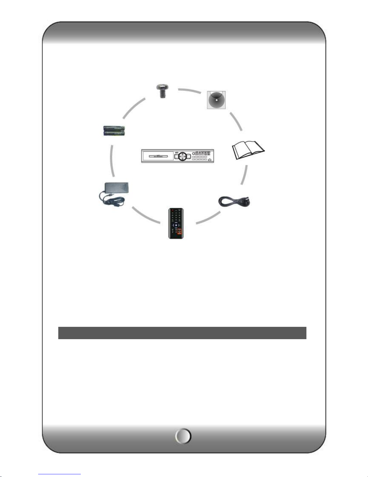
∙Contents ………………………………………………………………………………………………… 7
∙Rear panel ……………………………………………………………………………………………… 8
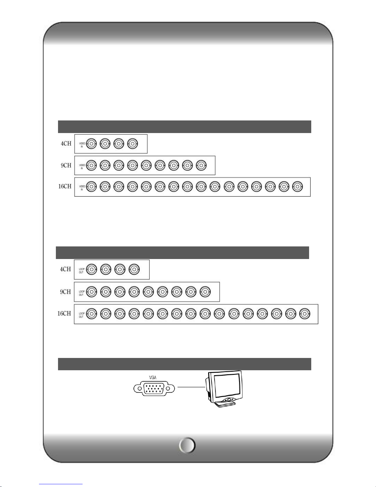
∙Video Input……………………………………………………………………………………………… 9
∙Loop Throughout put………………………………………………………………………………… 10
∙VGA output …………………………………………………………………………………………… 10
∙RS-485 connection (PTZ camera)………………………………………………………………… 10
∙RS-485 (Ext. keyboard connection)……………………………………………………………… 11
∙Alarm out connection ………………………………………………………………………………… 11
∙Sensor connection …………………………………………………………………………………… 11
∙RJ-485 port …………………………………………………………………………………………… 12
∙USB port ……………………………………………………………………………………………… 12
∙How to call Setup menu…………………………………………………………………………… 12
3. System configuration
∙Front panel button …………………………………………………………………………………… 13
∙Front direction key …………………………………………………………………………………… 16
∙Mouse…………………………………………………………………………………………………… 17
∙Icon ……………………………………………………………………………………………………… 17
∙How to setup the remote controller ID …………………………………………………………… 18
4. System configuration
∙Information ……………………………………………………………………………………………… 20
∙Date / Time ……………………………………………………………………………………………… 21
∙Password ………………………………………………………………………………………………… 22
∙Disk Manager …………………………………………………………………………………………… 23
∙Upgrade ………………………………………………………………………………………………… 24
∙Button Setup …………………………………………………………………………………………… 25
∙Default Setting ………………………………………………………………………………………… 26
∙Configuration …………………………………………………………………………………………… 26
∙Log out …………………………………………………………………………………………………… 27
5. Record
∙Record……………………………………………………………………………………………………… 27
∙Schedule Record………………………………………………………………………………………… 28
6. N/W Setup
∙IP Address………………………………………………………………………………………………… 31
∙DDNS Option……………………………………………………………………………………………… 33
∙E-Mail
Setup………………………………………………………………………………………………………… 34
∙E-Mail Notification……………………………………………………………………………………… 35
7. Camera Setup

4
∙Camera Setup…………………………………………………………………………………………… 36
∙Camera Title…………………………………………………………………………………………… 37
∙PTZ Setup……………………………………………………………………………………………… 37
∙PTZ Touring…………………………………………………………………………………………… 39
∙How to use PTZ……………………………………………………………………………………… 40
∙Serial port setup……………………………………………………………………………………… 44
8. Display setup
∙OSD……………………………………………………………………………………………………… 45
∙Split Mode……………………………………………………………………………………………… 45
∙Display…………………………………………………………………………………………………… 50
9. Event Setup
∙Sensor …………………………………………………………………………………………………… 50
∙Alarm …………………………………………………………………………………………………… 52
∙Motion Detection ……………………………………………………………………………………… 53
∙Internal buzzer ……………………………………………………………………………………… 54
∙SPOT OUT……………………………………………………………………………………………… 55
∙Audio …………………………………………………………………………………………………… 56
10. Search
∙Search …………………………………………………………………………………………………… 57
∙Calendar search..……………………………………………………………………………………… 58
∙Date/Time search .…………………………………………………………………………………… 59
∙Event search …………………………………………………………………………………………… 59
∙Go To First / Go To Last..…………………………………………………………………………… 60
∙Search control ………………………………………………………………………………………… 60
∙Back-up ………………………………………………………………………………………………… 61
11. Appendix……………………………………………………………………………………………… 64

5
1 —Summary
This Stand Alone Digital Video Recorder is capable of high quality of video and audio data
recording and provides various ways of data search by Calendar, Date/Time and event. Also
the system allows remote user to access in order to monitor and control multiple local DVRs
via TCP/IP / LAN connection.
Main features
(1) High resolution live display
(2) Easy installation and operation
(3) Motion detection record
(4) Sensor and Alarm outputs
(5) Reserved recording (Motion, Sensor/Alarm and time selected record)
(6) Network control via Dynamic IP
(7) NTSC / PAL compatible
(8) Highest data compression of H.264 technology
(9) Data backup to USB memory stick or DVD R/W
Application
(1) Bank, ATM unit, Supermarket, Convenient store and other public places.
(2) Private homes, Apartment, Jewelry shop, Commercial compound and other places
where it needs anti-theft surveillance system.
(3) Warehouse, Production line and other places where evidence is needed after any
event happened and to analyze the situation.
(4) Where to monitor sites remotely
2 —Installation
Feature
Contents
Program CD
HDD fixing screw
(8PCS)

6
Accessories.
ㆍDigital Video
Recorder (1EA)
ㆍHDD Fixing screw
(8pcs)
ㆍProgram CD (1EA)
ㆍManual (1EA)
ㆍPower code (1EA)
ㆍRemote controller)
ㆍBattery AAA (1.5V 2EA)
ㆍAdaptor (1EA)
[Note] Check the accessories before use.
Rear panel
DIGITAL VIDEO
RECORD
Battery
for
remote
controller
Size :
AAA
1.5V X
2EA
Adaptor

7
( KVR-H410AN )
( KVR-H920AN )
( KVR-H1640AN )

8
[1] Video Input [2] Loop Through [3] RJ-45(Ethernet) [4] USB 2.0 port
[5] RS-485 [6] Alarm output [7] Sensor Input [8] Serial Port (RS-232)
[9] Audio Input [10] Audio output [11] S-Video [12] VGA Out
[13] Composite Out [14] SPOT OUT [15] Power Input [16] Power switch
Connect video cable from camera to the BNC connector.
Loop out for each camera image without any image processing or disturbance.
Connect the PC monitor (LCD / CRT).
VGA Output
Video Input
Loop Through Out put

9
PTZ Camera
Connect the PTZ camera which is supporting its protocol as per the above diagram.
Connect the external keyboard that should be purchased by the DVR manufacturer.
DVR supports 1 alarm output as above diagram.
RS-485 connection (PTZ camera)
RS-485 (External keyboard connection)
Alarm out connection
Sensor connection

10
DVR supports 4 Sensor input as above diagram.
The network connection can be made through the 10/100/1000Mb Ethernet connector by RJ-
45.
DVR supports two USB 2.0 port on front and rear panel for mouse control, firmware upgrade
and backup use.
DVR can be operated by using front buttons, remote controller and mouse.
∙By front button
Press “MENU” button.
∙By remote controller
Press “MENU” button on the controller.
∙By mouse
Click the right button of mouse.
RJ-45 port (Internet connection)
USB port
How to call Setup menu

11
3 —System configuration
(Front button)
(Mouse menu icon)
Front panel button

12
(Remote controller)
[1] MENU
· Call main menu
· Move back to previous menu
[2] PTZ
Button to call PTZ controller menu, PTZ channel must be selected as full screen first.
[3] IR Receiver
Receive the IR signal from remote controller.
[4] SEARCH
Call search menu to playback record image.
[5] QUAD
Switch to multi-channel mode.
[6] LOG OUT(KEYLOCK)
• Using front button or remote controller, press and hold (about 4 sec) to log out.
• Using mouse, click the “LOCK” icon then front button operation is restricted. (Key lock)
[7] SCHEDULE RECORD
Press button to start scheduled recording in emergency record model.
[8] EMERGENCY RECORD
In case of emergency, press “EMERGENCY” button to star recording forcibly regardless
of the recording schedule.
[9] AUDIO

13
Select an audio channel.
[10] AUTO SEQUENCE
To display each camera in sequence, display duration is selectable in DISPLAY menu.
[11] BACKUP
Call backup menu to start recorded data archiving to external media.
[12] Channel / Numeric button
Refer to the “Front direction button”page.
[13] LED
LED shows the status of operating.
•POWER : Highlight when power is on.
•RECORD : Highlight when DVR is recording.
•NETWORK : Highlight when DVR is connected by network.
•SCHEDULE : Highlight when DVR is recoding on scheduled mode.
•EMERGENCY : Highlight when DVR is recording on emergency mode.
[14] ERROR LIST
In case of system error, the error icon appears on screen with beep sound. Press
“ENTER” button to see
the list and to stop beep sound.
Icon will be shown in the status bar.
•Main Disk1 Error : 1st HDD error.
•Mirror Disk Error : “Mirror Disk” HDD error.
(Unless use Mirror disk, message “Main Disk2 Error” will be shown)
•DNS Connection Error : Dynamic IP service fail.
•SMTP Connection Error : “E-mail notification” fail.
•Disk Full : Hard disk drive is full.
[15] SPLIT GROUP SETTING
In the split group, press “▶” button to change a channel on each group.
[16] CHANGING SPLIT MODE
Press to change for various split mode.
[17] ID
To control several DVRs using one remote controller, assign the ID to DVR and remote
controller.

14
[1] Left button
∙Menu move to left
∙Reverse playback speed control
[2] Upper button
∙Menu move to up
∙Change split mode in live
[3] Playback and Confirmation button
•Confirm the configuration in setup menu.
•Play / Pause button in search mode.
•Log out (Press more than 2 second)
•Stop beep and show error list when system error.
[4] Right button
∙Menu move to the right.
∙Playback speed control
[5] Lower button
∙Menu move to down
•Stop button in search mode.
PC mouse can be used to operate and control all the system function, this feature is for the
users who are familiar to PC environment.
Selection Click right side mouse button to open main menu.
Click selection button to use ◀, ▶, ▲, ▼ on
each configuration..
Menu call and
Move back to previous
PS/2 MOUSE USB MOUSE
Front direction key
Mouse

15
Daylight Saving Time Network connection icon
Emergency recording Sensor recording
Schedule recording Motion detection
Key lock status icon Video Loss
Auto sequence icon Record icon
Internet connection icon De-interlace icon
In order to use remote controller, the ID must be same both DVR and remote controller.
By assigning DVR ID, it allows the user to control multiple DVRs with one remote
controller.
[1] Check current system ID and can be changed by user. (Factory default ID: “0”)
Menu > Information > Remote ID (Range: 0 ~ 99 )
System ID must be configured on DVR system menu. It cannot change DVR system on
remote controller.
[2] How to use remote controller
ID must be identified between remote controller and system. Otherwise remote
controller cannot recognize DVR correctly.
Icon
How to setup the remote controller ID

16
[3] Remote controller ID menu displays as above image when you click ID button of
remote controller.
∙DVR ID : It displays current ID of the system.
∙“00” : Input the same ID number of DVR and press “Confirm”
[Note]
∙The DVR can be controlled once the ID between the DVR and remote controller is same so,
if the DVR is not working, please check the ID.

17
4 —System configuration
[1] Language : Select a language
[2] REMOCON ID : Assign the ID of remote controller, so that user can separately control
multiple
DVR unit with one controller. (ID range: 0 ~ 99)
[3] MOUSE Sensitivity : Mouse sensitivity level can be adjusted at user’s convenience.
(Basic Level 1; Slow speed, Level 1 < Level 2 < Level 3 to increase reaction speed.)
[4] Version
•H/W Version : Hardware version
•S/W Version : Software version
•N/W Version : Network version
•UI Version : User Interface version
[5] Web Code : Identification for remote monitoring of dynamic IP user.
Please refer to the CMS manual or Network menu.
[6] Mac Address : MAC address of system
[7] Video Standard : Select a video standard of your region then press “APPLY”.
( System is reboot automatically and applied)
INFORMATION

18
[1] YY / MM / DD : select a display format.
•ASIA : YYYY/MM/DD --> 2006/05/31
•US : MM/DD/YYYY --> 05/31/2006
•EURO : DD/MM/YYYY --> 31/05/2006
[2] Daylight Saving Time : It is commonly called as “Summer time”. During the period,
user can change system time 1 hour early or late.
[3] Time Server : It helps time set of DVR automatically by synchronization of time server
service.
•Time server : Input the URL of server
•Sync Cycle : Select the period to syncronize between DVR and time server
•GMT : Select GMT time zone where user located in.
•TEST : Check the connection status of time server.
[Note]
•In case DVR is not connected with internet or time server name is not collect, DVR gives
beep and error message. Press “CONFIRM”button to off sound and see a error message.
•GMT zone and time server name are searched easily on internet browser.
The administrator (Admin) has a whole authority to control the DVR and rest user may be
restricted their authority as per the user authority.
.
Date/Time
Password

19
[1] User ID : Able to input max. 8 user’s account.
[2] User Group : Select a group which is defined by functionality.
∙admin : Able to use all functions.
∙power User : Able to use Configuration, Search, Backup.
∙User : Choose a function to use.
[3] Password : Input the new P/W for the selected ID. (Max. 8 digit)
[Note] Default password of all ID is “11111111”.
[4] Authority : Select a function to allow on each user’s authority.
[5] Camera allocation : Select an allowable camera on each user.
It is the HDD and ODD setup. Since it is closely related to the record, if the setup is wrong, it
may cause the mal functioning.
Disk Manager

20
[1] Disk1 : Priority disk drive information..
• Main Disk : Use as a recording disk.
• Mirror Disk : Use as a mirroring disk.
• None : No use.
[2] DISK2 : Secondary disk drive or ODD (CD/DVD-RW) information.
In case of using ODD, “RW Write” info will be shown.
• Main Disk : Use as a recording disk
• Mirror Disk : Use as a mirroring disk
• None : No use.
[3] FORMAT : Initialize a disk drive.
[4] TOTAL : Display total HDD capacity. ( Occupied size / Available size )
[5] Over write: It is to set overwrite option when the HDD is full. System will overwrite from
the
firstly saved data in the HDD.
[6] Auto Delete : The function is to keep recorded data in HDD during only for specified
period. (Range: 1~120days)
[7] CD /DVD RW : Status of installation of CD or DVD writer.
In order to improve system performance or adding new function, firmware upgrade is needed.
[1] F/W Upgrade : In order to upgrade system firmware with USB memory stick, the
firmware file
must be saved in the USB storage first and then insert to DVR to start USB upgrade from
the
UPGRADE
This manual suits for next models
2
Table of contents
Other KT&C DVR manuals