MK60SP 12/10/20 KEENAN FILTERS® by KTI Systems, Inc. www.keenanfilters.com
MK60SP MOUNTING LOCATION
1. The filter assembly should be installed between the fuel tank (fuel source)
and the suction side of the engine lift or transfer pump. Pre-existing
filters should be removed. If the engine manufacturer has permanently
installed primary filters, service with new filter elements.
2. The filter assembly should be mounted between the horizontal plane of the engine
lift or transfer pump inlet and the bottom of the fuel tank. The filter must be
mounted in a vertical position on a structure that is also vertical (DO NOT MOUNT
ON ENGINE) with the Tee-handle on top. Enough space should be left above and
below the unit to service the filter. Allow about 5” above the filter to remove and
replace the filter element and at least 2” below to drain the filter.
USE APPROPRIATE MOUNTING HARDWARE
3. A shut off valve should be installed in the inlet side of the filter, which will allow for
system testing. If the fuel tank (fuel source) is located close to the filter, the fuel
tank supply shut off may be used.
4. If the fuel tank (fuel source) is mounted higher than the filter, a shut off valve
must be installed into the inlet of the filter assembly. This will stop the flow of
fuel when servicing the filter or fuel system.
5. Location of the filter should allow for easy access while servicing and away
from anything that can injure the operator, such as hot and/or moving
equipment.
6. Use appropriate fuel line with the least amount of restriction, such as 3/8” to
1/2” ID to supply the MK60SP/K60SP. Avoid sharp 90 degree bends. Route
fuel lines away from sharp objects and heat.
7. Consider the pump switch location, circuit protected (circuit breaker) 12 volt
power source and wire conduit locations.
MK60SP INSTALLATION
1. The MK60SP/K60SP pump assembly is factory mounted on the left side of the unit
and can be move to the right side by a qualified technician. This can be
accomplished by disconnecting the pump inlet and outlet fittings and removing the
pump and mounting bracket. Remove both the right and left side 3/4-16 orb (O-
ring boss) fittings and reinstall on the opposite side. Install the pump mounting
bracket on the right side, install the pump onto the mounting bracket. Loosen and
remove the 3/4” hex bolt and fuel filter bowl. Lubricate the bowl O-ring and re-
install bowl assembly, but do not tighten 3/4” bolt. (this will allow the installer to
rotate the pump bowl to align the inlet fitting). Reposition the fittings as needed to
make proper alignment connections and tighten connections, next tighten 3/4”
bowl hex bolt.
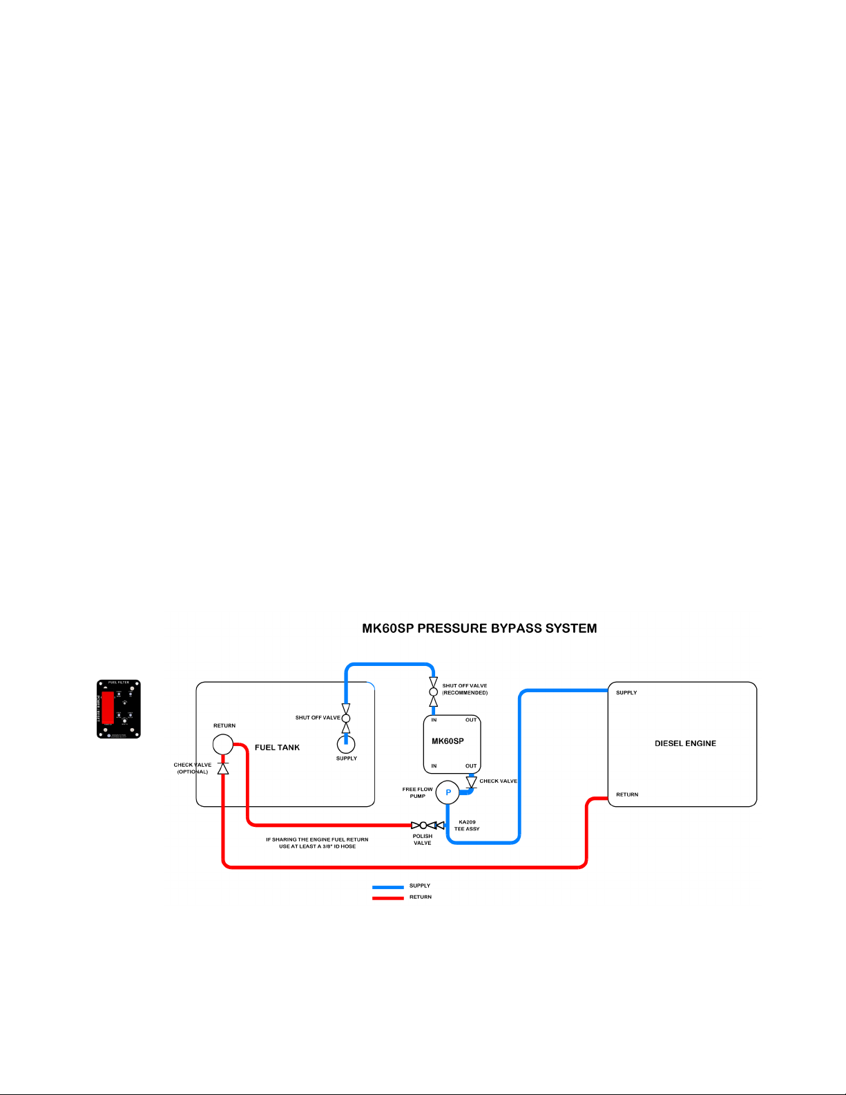
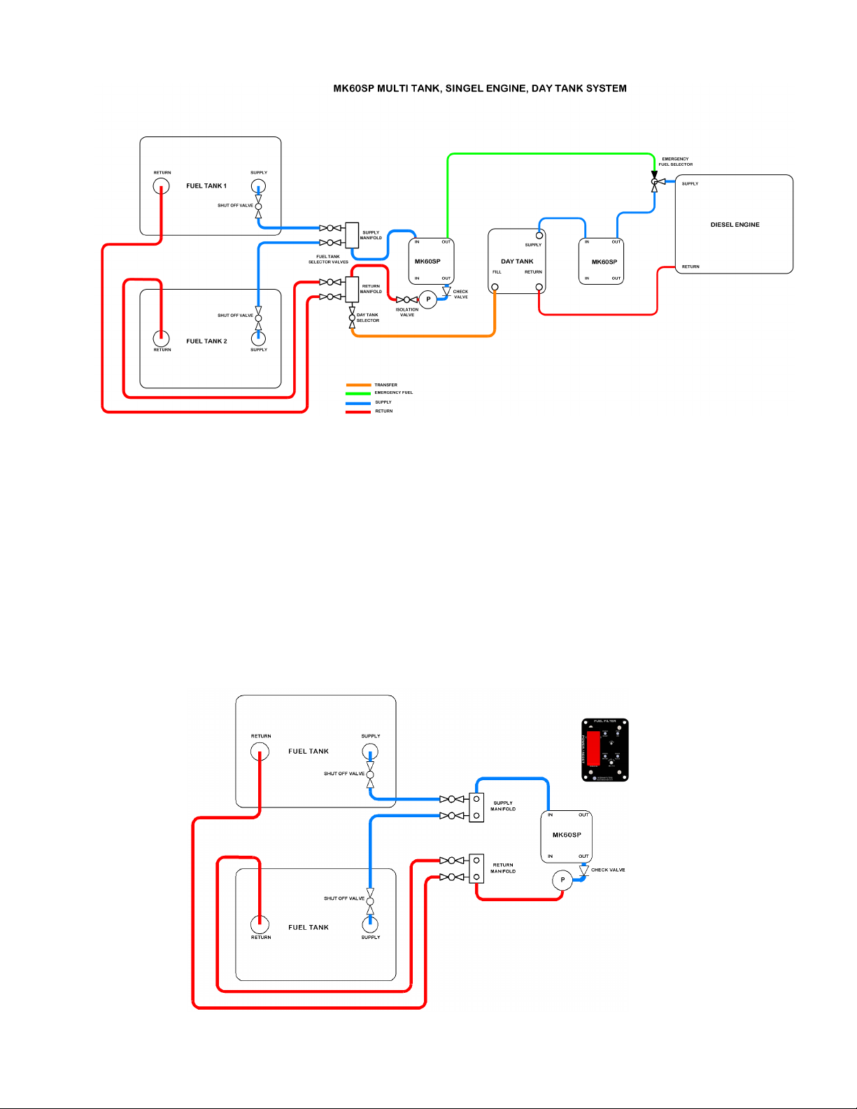
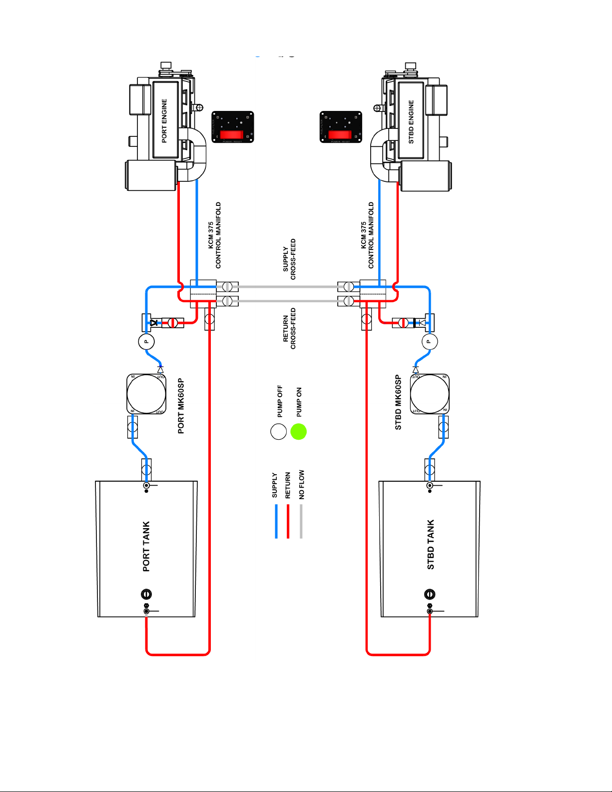
2. The MK60SP/K60SP filter pump system can be installed in several configurations,
(see previous basic fuel system designs) but it is still the operator, designer and
the installers responsibility to configure the system properly.
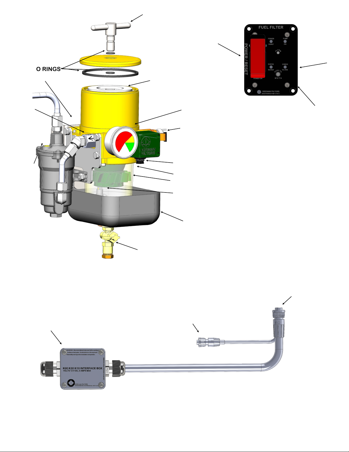
PUMP
OUTLET
SHUT OFF
VALVE
FILTER
OUTLET
PAGE 6