New Holland 611TL User manual

OPERATOR’S MANUAL
611TL
616TL
621TL
626TL
Loader
Part number 47920980
Ref (60001421)
2nd edition English
August 2015
Replaces part number 47862941
ORIGINAL INSTRUCTIONS


214809
1
TABLE OF CONTENTS
1. INTRODUCTION...................................... 2
1.1. General information.................................................... 2
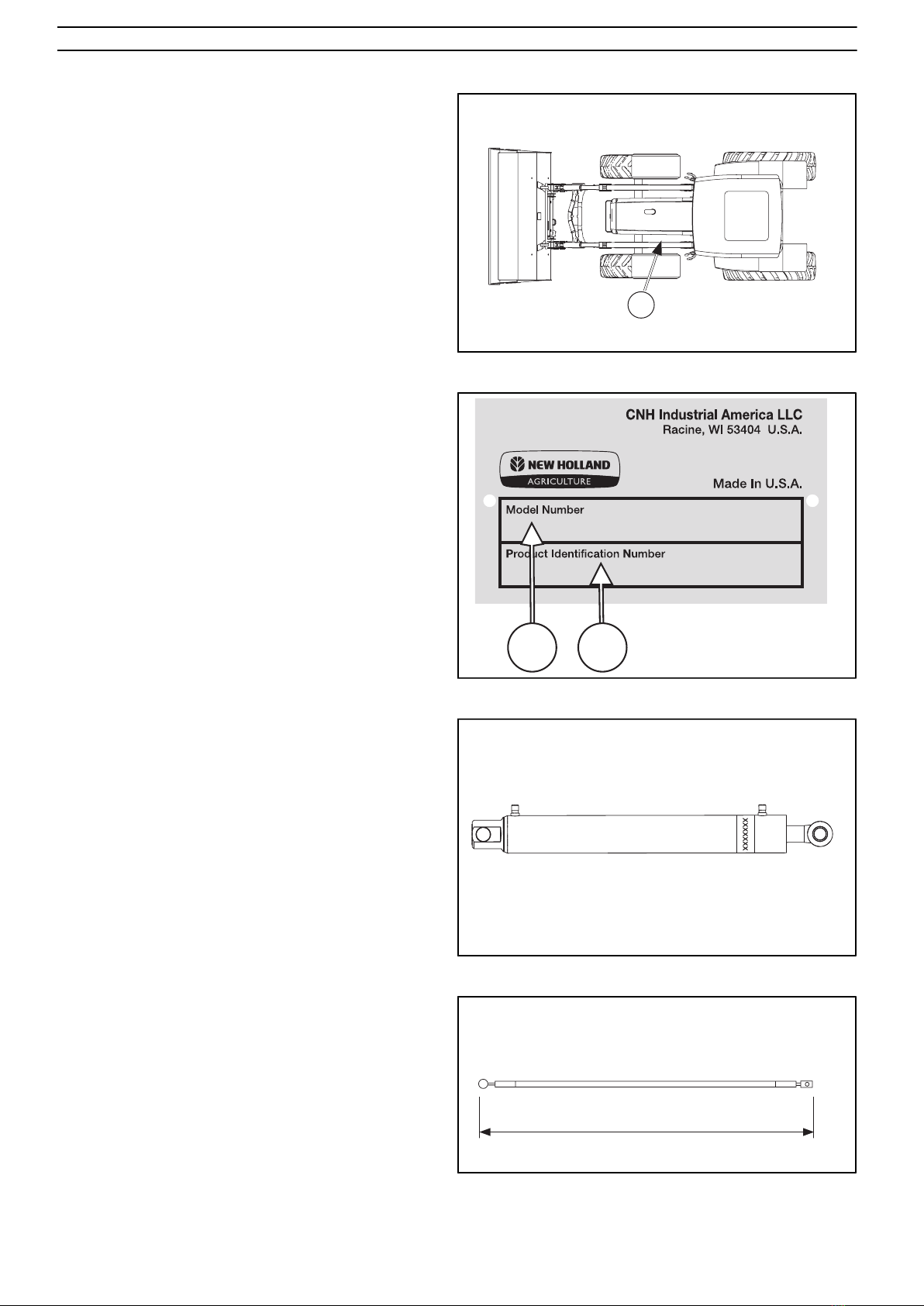
1.2. Identification................................................................3
1.2.1. Model and serial number........................................3
1.3. Alignment reference....................................................4
2. DESCRIPTION......................................... 5
2.1. Definitions................................................................... 5
2.1.1. Position indicator....................................................5
2.1.2. Control valve.......................................................... 5
2.1.3. Tool carrier............................................................. 5
2.1.4. Hose kit...................................................................5
2.1.5. Loader with mechanical self-levelling....................5
2.1.6. Loader without mechanical self-levelling...............5
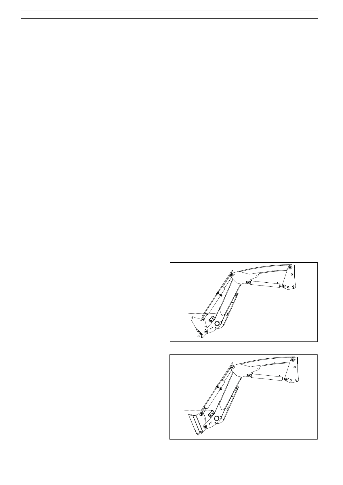
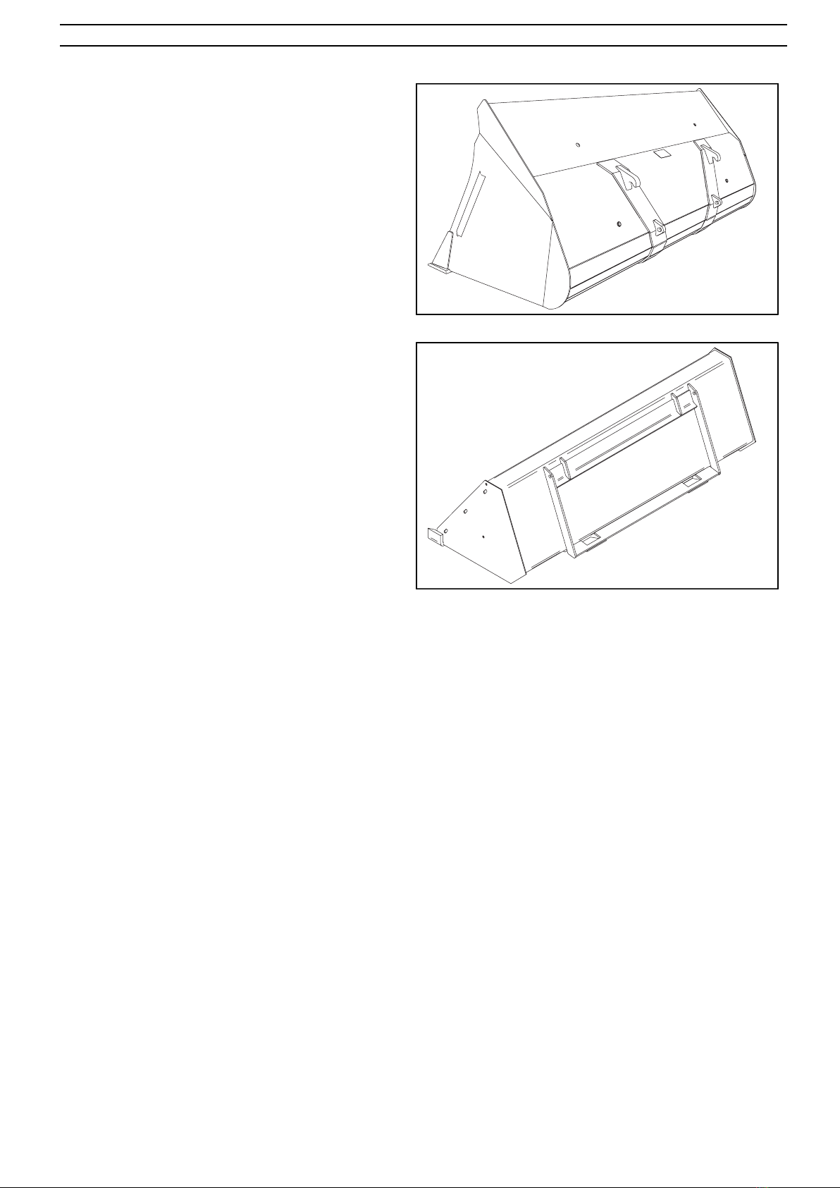
2.2. Tool carrier.................................................................. 5
3. SAFETY INSTRUCTIONS........................7
3.1. General information.................................................... 7
3.1.1. Guards.....................................................................7
3.1.2. Safety signs.............................................................7
3.2. Signal words................................................................7
3.3. Symbol explanation.....................................................8
3.3.1. Operator's manual...................................................9
3.4. Installing the loader.....................................................9
3.4.1. Joystick operation................................................... 9
3.5. Protection equipment.................................................10
3.5.1. Roll Over Protective Structure (ROPS)................10
3.5.2. Counterweight and tread width............................ 10
3.6. Before work...............................................................11
3.7. Operation................................................................... 11
3.7.1. Operator's position................................................11
3.7.2. Workplace............................................................. 12
3.7.3. Load stability........................................................ 14
3.7.4. Machine stability.................................................. 15
3.8. Risk factors during operation....................................16
3.8.1. During transport....................................................16
3.8.2. During service.......................................................17
3.8.3. Replacement parts.................................................17
3.9. Location of safety signs............................................ 18
4. INSTALLING THE LOADER..................19
4.1. Install the position indicator......................................20
4.2. Check list...................................................................20
5. OPERATION...........................................21
5.1. Tractor/Loader Stability............................................ 21
5.1.1. Determination of Ballast.......................................21
5.1.2. Minimum Tread Settings...................................... 21
5.1.3. Joystick operation................................................. 22
5.2. Connection and Operation Options...........................22
5.3. Disconnecting a loader..............................................22
5.4. Connecting a loader.................................................. 23
5.5. Loader Operation.......................................................25
5.5.1. Counterweight and tread width............................ 26
5.5.2. Checking attachment............................................ 26
5.5.3. Load stability........................................................ 27
5.5.3.1. Machine stability..............................................28
5.6. Operation with bale spike......................................... 29
5.7. Coupling and uncoupling implements.......................30
5.7.1. Uncoupling implements, Euro 8 Tool carrier....... 30
5.7.2. Coupling implements, Euro 8 Tool carrier........... 31
5.7.3. Uncoupling Implements, Skid Steer Tool
carrier.............................................................................. 33
5.7.4. Coupling Implements, Skid Steer Tool
carrier.............................................................................. 33
6. MAINTENANCE..................................... 35
6.1. Lubrication.................................................................35
6.2. Hydraulic system.......................................................35
6.2.1. Hoses and cylinders..............................................35
6.2.2. Repair/replacement of hydraulic components...... 36
6.2.2.1. Hydraulic cylinders..........................................36
6.2.2.2. Hydraulic hoses................................................36
6.3. Checking the loader and subframe hardware............ 36
6.3.1. Torque................................................................... 36
6.3.1.1. Table - Torque..................................................37
6.4. Storage....................................................................... 37
6.5. Transporting the loader............................................. 37
7. TROUBLESHOOTING........................... 38
8. SPECIFICATIONS.................................. 41
8.1. Weight of materials................................................... 42

Introduction
214812
2
1. INTRODUCTION
1.1. General information
WARNING:
Careless or incorrect use may result in serious
injury or fatality to the operator or others.
Observe the safety instructions.
This operator's manual describes the operation and
maintenance of an agricultural loader. The information in
the operator's manual was correct at the time this manual
was printed. Please visit your dealer if there is anything you
do not understand in the manual.
One operator's manual is supplied with every machine in
order to show the operator how it should be operated and
maintained. Read and use the information so that you can
use the machine in a safe manner. This machine is designed
with simple service in mind, and it can be maintained with
normal hand tools.
Read and study the text in the operator's manual thoroughly
before you begin to use the machine. If you are not an
experienced operator, study the operator's manual and ask
an experienced operator to explain things to you. Your
dealer can help you by teaching you about operation and
suitable work methods. Keep this operator's manual readily
available, preferably with the tractor. Contact your dealer
to obtain a replacement manual, if the original manual is
damaged or missing.
WARNING:
Read through the entire operator's manual
before you begin to use the machine.
We reserve the right to introduce changes to the design and
specification, or improvements at any time, without prior
notice or commitment.
IMPORTANT: The loader subframe is designed to suit
specific models of tractors. Do not install a loader subframe
on another model of tractor without prior permission from
the manufacturer.
Installation and operating instructions for implements and
accessories are not included in this operator's manual. Use
the publications supplied with each implement.
Fig. 1 Read through the entire operator's manual before you
begin to use the machine.

Introduction
214812
3
1.2. Identification
1.2.1. Model and serial number
Each loader has an identification plate (A) with an
identification number. The plate is located on the inside of
the left arm.
A
Fig. 2 Location of identification plate.
The plate specifies:
Model number and Product Identification Number.
A. Model Number
B. Product Identification Number
AB
Fig. 3 Machine sign.
Cylinders, valves, control cables and hoses are also
equipped with machine signs or punched/printed part
numbers.
Fig. 4 Marking of components, e.g., cylinder.
When ordering replacement control cables, please specify
the control cable length (L) and make of control valve.
L
Fig. 5 Indicate length when ordering control cable.

Introduction
214812
4
1.3. Alignment reference
Throughout this operator's manual, references to the
right and left are seen from the operator's seat in forward
direction.
NOTE: Some illustrations in this operator's manual may
show a model of tractor or loader that is different from your
loader. However, the same information will apply to your
equipment unless otherwise specified.

Description
224471
5
2. DESCRIPTION
2.1. Definitions
2.1.1. Position indicator
Device to indicate the angular position of the implement.
2.1.2. Control valve
Valve designed for controlling the operation of the loader.
2.1.3. Tool carrier
Type 8 = Euro in compliance with ISO 23206.
SSL = Skid Steer Loader Style
2.1.4. Hose kit
Hoses and hydraulic components for connecting the loader
to the tractor's original hydraulic valve or factory mid
mount loader valve.
2.1.5. Loader with mechanical self-
levelling
The loaders that are equipped with mechanical self-
leveling have parallel links that keep the implement in the
same angular position during the entire lifting/lowering
movement.
2.1.6. Loader without mechanical self-
levelling
The implement changes its angle in relation to the ground
during the entire lift/lowering movement.
2.2. Tool carrier
The loader can be fitted with two styles of tool carrier Euro
Type 8 or SSL (skid steer loader) style. Consult your dealer
as to the style of system of your loader.
IMPORTANT: Incorrectly designed implements can
damage the loader. For this reason, do not install any
implement without making sure that it has been approved
by the loader manufacturer.
Fig. 6 The loader can be fitted with the Euro 8 tool carrier.
Fig. 7 The loader can be fitted with the Skidsteer (21) tool
carrier.

Description
224471
6
Use only approved implements adapted to the loader and
suited for the work at hand.
Fig. 8 Euro attaching plate
Fig. 9 SSL (skid steer loader) attaching plate

Safety instructions
224473
7
3. SAFETY INSTRUCTIONS
3.1. General information
Operator safety is one of the most important concerns when
designing a new loader. The designer builds in as many
safety features as practicable. However, several accidents
occur every year that could be avoided by a few seconds of
reflection and more careful operation of the machine.
Avoid personal injury. Read the following personal safety
instructions and insist that everybody who works with you,
or for you, also complies with the instructions.
Only use implements that have been approved by the
manufacturer of the loader for use with the loader.
3.1.1. Guards
This operator's manual contains a number of illustrations
which show guards removed for better visibility. Never
use the machine with guards removed. If a guard has been
removed for service or repairs, re-install the guard before
the machine is taken back into service.
3.1.2. Safety signs
Safety signs are installed at different locations on the loader
and implement. Locate, read and find out what the safety
signs mean before using the loader and implement. See
section 3.9. Location of safety signs.
Do not cover or remove any of the safety signs. If a safety
sign is missing or illegible, replace it with a new safety
sign. New safety signs can be obtained from your dealer.
Fig. 10 Locate, read and find out what the safety signs mean
before using the loader and implement.
3.2. Signal words
When you see the safety alert symbol and the signal word
on safety signs or in the operator's manual, the instructions
MUST be followed since they are related to your own
personal safety.
DANGER:
Means an imminently hazardous situation that,
if not avoided, will result in DEATH OR VERY
SERIOUS INJURY.
WARNING:
Indicates a potentially hazardous situation
that, if not avoided, could result in DEATH OR
SERIOUS INJURY.
CAUTION:
Indicates a potentially hazardous situation
that, if not avoided, may result in MINOR OR
MODERATE INJURY.
Fig. 11 Safety alert symbol

Safety instructions
224473
8
The following signal words and instructions do not refer to
personal safety, but are used consistently in the operator's
manual to provide tips about operating or servicing the
machine.
IMPORTANT: Indicates a special instruction or procedure
which, if not strictly followed, may result in damage to, or
destruction of, the machine, the process, or surroundings.
NOTE: Indicates additional information about a subject
or procedure for more efficient or convenient repair or
operation.
3.3. Symbol explanation
A
Operator's manual. Read the operator's manual — it contains
important information for your safety.
B
Safety alert symbol. Means CAUTION! BE ALERT!
YOUR SAFETY DEPENDS ON IT! The safety alert
symbol identifies important safety notices on machines,
safety signs, in operator´s manuals or elsewhere. When
you see this symbol, be alert to the risk of injury or death.
Follow the instructions in the safety notice.
C
Implement lock. Verify that coupled implement is secured
correctly and locked in place.
12
D
Risk of crushing. Never stand between the front of the
tractor and the cross tube on the loader.
E
Risk of falling. Do not use the loader to lift or transport
people.
F
Electric shock. Get to know the site and the ground. Be
aware of overhead power lines and other obstructions.
G
Overturning risk. The tractor can overturn and result in
personal injury.
H
Fall risk. Do not use the loader or the implement/bucket as a
working platform.

Safety instructions
224473
9
I
Crush risk. Objects can fall or roll backwards when the
loader is raised. Only lift loads which can be secured by the
implement.
3.3.1. Operator's manual
Always store this operator's manual as well as the tractor's
own operator's manual with the tractor.
• If there is no operator's manual included with the
tractor then obtain one from the dealer before installing
and using the loader.
• Read through all material carefully and learn how to
operate the equipment in a safe and correct manner.
• Only qualified persons are to operate the machine.
Fig. 12 Always store this operator's manual as well as the
tractor's own operator's manual with the tractor.
3.4. Installing the loader
The loader must not be connected in series with any other
of the tractor's functions. Working with the loader will
require the full attention of the operator.
Fig. 13 The loader must not be connected in series with any
other of the tractor's functions.
The tractor and loader use fluids that are under high
pressure during operation. Check all components and
maintain them in good condition.
Make sure that no hydraulic components, especially hoses,
are damaged or in contact with moving components.
Fig. 14 NEVER use fingers or hands to detect leaks.
3.4.1. Joystick operation
In order to prevent unintended loader motion, the loader
joystick controller must be designed to self neutralize.

Safety instructions
224473
10
When the operator releases his grip on the joystick, the
joystick must return to a non-operational neutral position
except for the float position in loader lower and bucket
dump circuits.
3.5. Protection equipment
Seat belt must be worn and correctly adjusted during
machine operation except when operating with the ROPS
folded down. Replace a damaged seat belt before operating
the machine.
Fig. 15 Wear the seat belt when operating the machine.
3.5.1. Roll Over Protective Structure
(ROPS)
The tractor must be equipped with a roll-over protective
structure (ROPS) - frame or cab.
Use the loader only on a tractor with the ROPS installed.
Whenever possible, operate the tractor and loader with
the ROPS in the upright and locked position and the seat
belt fastened and correctly adjusted. When operating in
restricted overhead environment with the ROPS folded
down, do not wear the seat belt. ALWAYS return the ROPS
to the upright and locked position as soon as operating
conditions permit.
Fig. 16 Rollover risk - wear the seatbelt.
3.5.2. Counterweight and tread width
Make sure that the machine has ballast (counterweight) at
the rear to stabilize the machine's load-carrying ability. The
counterweight is essential for maintaining control of the
machine.
Refer to section 5. Operation in the operator's manual
for information on the counterweight and tread width.
Also refer to the tractor operator's manual for further
information.
IMPORTANT: Incorrectly designed implements can
damage the loader. For this reason, do not install any
implement without making sure that it has been approved
by the loader manufacturer.

Safety instructions
224473
11
3.6. Before work
Familiarize yourself with the working area and terrain.
ALWAYS inspect the work area before starting work. Look
out for holes in the ground, stones and other hazards.
• Do NOT operate a machine that is broken or lacks any
component. Make sure that recommended maintenance
work has been carried out before the machine is used.
• Check all controls regularly and adjust as necessary.
Make sure that the tractor's brakes are adjusted
correctly.
• Check all screws and nuts regularly for tightening,
especially those that secure the tractor wheels.
See section 6. Maintenance for information about
tightening torques.
• Make sure that the loader is correctly mounted to the
tractor, and that all pins are secured.
• Change worn components before using the machine.
Fig. 17 Familiarize yourself with the working area before
starting. Maintain a safe distance from electrical cables and
other obstructions.
3.7. Operation
3.7.1. Operator's position
Only operate the machine when sitting in the operator's
seat.
Fig. 18 Only operate the machine when sitting in the operator's
seat.
• Drive carefully and think about safety.
• Always leave the brake pedals locked to each other.
NEVER use split brakes with a loader mounted to
avoid the risk of losing control of the tractor and/or the
tractor overturning.
• Always adjust the speed to prevailing conditions.
Never drive so fast that you cannot stop quickly in an
emergency situation.
Fig. 19 Always leave the brake pedals locked to each other.

Safety instructions
224473
12
3.7.2. Workplace
Always check the machine's surroundings and ensure
that all individuals, especially children, and animals have
moved away before starting or operating the machine.
You may not hear warning cries from individuals on the
outside when you are sitting in the cab with the door closed.
Fig. 20 Before starting, make sure that nobody is in the vicinity
of the machine.
Make sure that the bucket or other implement is correctly
installed on the tool carrier and that the pins are in the
locked position. Press the front end of the implement
against the ground to make sure that the implement is
properly secured.
1
2
Fig. 21 Make sure that the implement is secured by pressing its
front end against the ground.
Familiarize yourself with the working area and terrain. Pay
attention to vertical clearance and limitations that arise due
to the increased reach.
Fig. 22 Familiarize yourself with the working area before
starting. Maintain a safe distance from electrical cables and
other obstructions.

Safety instructions
224473
13
Do NOT use the loader or the implement/bucket as a work
platform.
Fig. 23 Do NOT use the loader or the implement/bucket as a
work platform.
Do NOT use the loader to lift or transport people.
Fig. 24 Do NOT use the loader to lift or transport people.
Do NOT stand, walk or work under a raised loader. Make
sure that people, especially children, and animals are kept
away from the working area.
Fig. 25 Do NOT stand, walk or work under a raised loader.
WARNING:
Never stand between the front of the loader and
the cross-tube on the loader.
Never stand between the front of the tractor and the loader's
cross tube.
Fig. 26 Never stand between the front of the tractor and the
loader's cross tube.

Safety instructions
224473
14
3.7.3. Load stability
Pay attention to the loader and implement positions.
Objects can fall or roll backwards onto the operator or a
bystander when the loader is raised.
Only lift loads which can be contained in, and are intended
for, the specific implement.
Fig. 27 Pay attention to the loader and implement positions;
objects may fall off.
If the tractor is only equipped with Roll Over Protective
Structure (ROPS), and does not have a Falling Objects
Protective Structure (FOPS), there is only limited protection
against falling loads. The operator risks injury if the load
falls when the loader is being operated at height.
Exercise caution when working with raised loads.
• Only use implements that are approved for the relevant
application.
• Make sure that the load is positioned securely in
the implement. When it comes to loose material,
the implement must not be overfilled, and for solid
material, the load must not stick up above the rear of
the implement.
Fig. 28 Only lift loads which can be contained in, and are
intended for, the specific implement.
• Adjust the tilt angle of the implement when the load
is raised so that the load is not directed towards the
operator.
Fig. 29 Exercise caution when working with raised loads.

Safety instructions
224473
15
Reduce speed before cornering to avoid overturning the
machine.
Avoid sudden turns when driving down slopes.
• Always leave the transmission in low gear to obtain
engine braking when driving downhill. Do not allow
the tractor to roll freely. Use the same gear for driving
downhill as you did when driving uphill.
• While driving, lower the loader as far as possible. Keep
in mind that the higher you raise the loader, the higher
the centre of gravity, and thus the risk of the tractor
overturning will increase.
Fig. 30 When cornering, lower the loader and reduce speed.
3.7.4. Machine stability
Do not work near the edge of ditches and banks as there
may be a danger of them collapsing.
The tractor must always be kept a distance from the edge
that is equal to or greater than the height of the bank or
ditch.
• Operate up and down (not across) slopes. Avoid sudden
starts and stops. Keep the loader as low as possible.
• Drive the tractor forward up slopes with an empty
bucket. Fill the bucket and then reverse slowly down
the slope.
Fig. 31 Keep at a distance when working near slopes.
Before leaving the operator's seat:
1. Lower the loader and implement to the ground.
2. Apply the park brake securely.
3. Move the gearshift to the neutral or park position.
4. Shut the engine off.
5. Remove the ignition key.
6. Move the control handle through all positions, then
return the control handle to the centre position in order
to relieve the hydraulic pressure.
Fig. 32 Lower the loader and remove the ignition key.
Joystick/Control lever: To prevent accidental operation of
the loader, lock the joystick in the neutral position.
Lock
Open
Fig. 33 Joystick/Control lever

Safety instructions
224473
16
3.8. Risk factors during operation
3.8.1. During transport
The SMV emblem, lights and reflectors may not be visible
when the machine is used for carrying or transporting loads
on public roads by day or at night. When this occurs, make
sure that extra warning material is used.
When transporting bulky load on public roads, make sure
that SMV-emblem, lights and reflector are visible and use
extra warning devices if needed. Fig. 34 During transport
When driving either with or without a load, always lower
the loader as far as possible to provide maximum visibility
and avoid obstructing lights.
• Remove or tilt the implement upwards to minimize the
risk of damage in the event of collision.
• Make allowances for the extra length and weight of the
vehicle when cornering, braking etc.
• Make sure that lamps and reflector are visible during
road transport and are not obscured by the implement.
Joystick/Control lever: The loader must not be operated
during transport. When transporting on public roads, the
control lever must be locked in neutral position. See section
5. Operation.
Do not grip objects that extend the centre of gravity to a
significant extent.
Always monitor the implement. Objects can fall or roll
backwards onto the operator when the loader is raised. Only
lift objects intended for the implement.
Always monitor the implement. Objects may fall out during
transport. Only transport objects that are intended for the
implement.
Fig. 35 Lower the loader to obtain maximum visibility.
Fig. 36 Always monitor the implement. Objects can fall or roll
backwards onto the operator when the loader is raised.
Fig. 37 Only lift loads that fit inside the implement.

Safety instructions
224473
17
3.8.2. During service
Do NOT carry out any service on the loader when the
tractor engine is running or is hot, or when the machine is
moving.
Fig. 38 Before service, read the instructions and remove the
ignition key.
Watch for pressurized hydraulic fluid.
NEVER use fingers or hands to detect leaks. Fluid that
flows out from small holes can be almost invisible. Use a
piece of wood or cardboard instead.
• Undo hydraulic couplings slowly. Keep your hands and
fingers away from loosened couplings.
• Get medical attention at once if fluid penetrates your
skin. Serious reactions and/or infections can rapidly
occur if the oil is not immediately removed by means
of surgery.
Fig. 39 NEVER use fingers or hands to detect leaks.
3.8.3. Replacement parts
When a replacement part is needed for periodic
maintenance or service, use only genuine, original
equipment replacement parts to restore your equipment to
original specifications.
The manufacturer is not responsible for damages that may
occur due to installation of non-approved parts and/or
accessories.

Safety instructions
224473
18
3.9. Location of safety signs
A
1123676
F
To avoid injury or death from falls:
• Do not work from or allow riders on loader or
its attachements.
Failure to comply may result in death or serious injury
11136096
To avoid injury or death caused by falling loads:
• Use recommended FOPS with loader application.
• Lockout optional valve detents.
• Carry loads low.
• Do not handle loose or shiftable loads with loader that are not contained in bucket.
• Handle raised loads with caution.
• Do not handle round bales or other large objects with loader unless manufacturer’s
approved round bale grapple or other approved bale handling equipment, is installed.
To avoid injury or death from falling loader:
• Do not walk or perform service under a raised loader.
• Lower loader to ground when parked.
• Before servicing, adjusting equipment or disconnection oil lines:
a) lower attachment to ground or support loader boom.
b) shut off engine and relieve hydraulic pressure.
Failure to comply may result in death or serious injury
• Observe safety precautions in Loader Operation and Maintenance Manual.
11136097
To avoid serious injury
or death from rollovers:
• Operate tractor at low speeds
with loader low to ground
• Add recommended rear ballast.
• Do not exceed the load weight limitations stated
in the loader Operator’s Manual to maintain
tractor stability.
• Move wheels to widest recommended setting.
• Use ROPS and seatbelts at all times.
Failure to comply will result
in death or serious injury
To avoid serious
injury or death from
electrocution:
•Stay Clear of Overhead
Electric wires
11136098
C
D
E
B
1123676
F
MSL
A. Safety sign implement lock, 1 pc.
Part no. 11135077
B. Warning decal on lower part of loader beam on right
and left side, 2 pcs.
(Part no. 11133557)
C. Safety sign on bearing box, 1 pc
(Part no. 11136096)
D. Safety sign on bearing box, 1 pc
(Part no. 11136097)
E. Safety sign on bearing box, 1 pc
(Part no. 11136098)
F. Lift decal, 2 pc.
(Part no. 1123676)
This manual suits for next models
3
Table of contents
Other New Holland Front End Loader manuals

New Holland
New Holland B100C User manual

New Holland
New Holland LS160 Instruction manual

New Holland
New Holland B110 Operating instructions

New Holland
New Holland B95C User manual

New Holland
New Holland L865 Operating instructions

New Holland
New Holland W190D User manual

New Holland
New Holland 430TL User manual

New Holland
New Holland B90BLR User manual

New Holland
New Holland C227 User manual

New Holland
New Holland B90B User manual