Kubota V0621-9860 User manual

1
AX. F. 1 - 1. 3. K Code No. V0621-9870-1PRINTED IN JAPAN KUBOTA Corporation 2019
1. Introduction
This is the instructon manual to install the fuel filter and water separator on KUBOTA compact track loader SVL90-2.
Please read this manual before starting to install it.
2. Parts list
PART NAME FILTER KIT (FUEL)
PART No. V0621-9860
REF. No. PART NAME PART No. Q’TY REMARKS
1 HOSE (FUEL) V0511-5118 1
2 PIPE (FUEL) V0511-5117 1
3 BRACKET (FILTER, 1) V0621-9861 1
4 BOLT 01125-50825 2
5 BRACKET (FILTER, 2) V0621-9862 1
6 STAY (HOSE CLAMP) V0621-9863 1
7 FUEL TUBE, ASSY (200) V0621-9864 1
8 CONNECTOR (HOSE) 3C131-4246 1
9 FUEL TUBE, ASSY (500) V0621-9865 1
10 FUEL TUBE, ASSY V0621-9866 1
11 FUEL TUBE, ASSY (770) V0621-9867 1
12 FUEL TUBE, ASSY (RETURN) V0621-9868 1
13 FILTER, ASSY (SEPARATOR) V0631-5186 1
14 BOLT 01135-51080 1
15 FILTER, ASSY (FUEL) V0631-5168 1
16 BOLT 01125-50830 2
17 TUBE, FUEL 09664-60400 1
18 W/H (CONVERSION, 2, WS-WH) V0621-9869 1
19 LABEL (MAINTENANCE) V0521-5756 1
20 LABEL (MAINTENANCE, FR) V0521-5956 1
21 INSTRUCTION MANUAL V0621-9870 1
22 MANUAL, OP (W-FILTER, TANK PIPE) V0621-9871 1 This booklet
INSTRUCTION MANUAL
W-FILTER KIT
for KUBOTA COMPACT TRACK LOADER SVL90-2

2

3
3. Required tools
AAfter disconnecting fuel tubes from pipes, insert plugs to the end of both tubes and pipes.
AClean plugs before using.
AIf any contaminant such as dust or dirt enter the fuel system, it may cause failure.
REF No. TOOL REMARKS
1 Flexible screwdriver
2 Nipper
3 Needle-nose pliers
4Pliers
5 Ratchet handle
6 Torque wrench Required torque: 9.81 to 90.2 N-m (1.00 to 9.1 kgf-m) [7.24 to 66.5 ft-lbs]
7 12 mm socket
8 14 mm socket
9 19 mm socket
10 24 mm socket
11 Extension bar (50 mm)
12 10 mm socket
13 10 mm long socket
14 12 mm long socket
15 Extension bar (75 mm)
16 Plug of male type 6: 1 piece, 10: 8 pieces
17 Plug of female type 6: 1 piece, 10: 8 pieces

4
4. Installation instruction
To avoid personal injury or death:
APark the machine on a firm and level ground
and set the parking brake.
ALower the bucket to the ground.
ASet all controls in their neutral positions.
ARelease all residual pressure of the hydraulic
system.
AStop the engine. Remove the key from the
ignition.
AThe engine, hydraulic components and
coolants can be hot. Wait until all the
components are cooled down sufficiently to
avoid burns.
AClean the work area and the machine.
ADisconnect the battery negative cable.
AHang a "DO NOT OPERATE" tag on the
operator station.
APut on working clothes and personal protective
equipment.
ARead all instructions and safety instructions in
this bulletin and safety labels on your machine.
AFollow the local safety regulations and/or laws
in your country.
AIf you are working with other people, make sure
that your signals and communications are fully
understandable for additional safety.
ADo not contact fuel tubes to sharp edges, high
temperature parts, and rotating parts.
ADo not stretch fuel tubes excessively.
ADo not clamp fuel tubes with electrical wiring.
ADo not flatten fuel tubes by the clamps.
ATake care not to leak fuel when disconnecting fuel
tubes.
A) Preparation
After the following steps 1 to 5, install the necessary parts
according to the installation manual B), C) and D). If
necessary for the details, see the WSM.
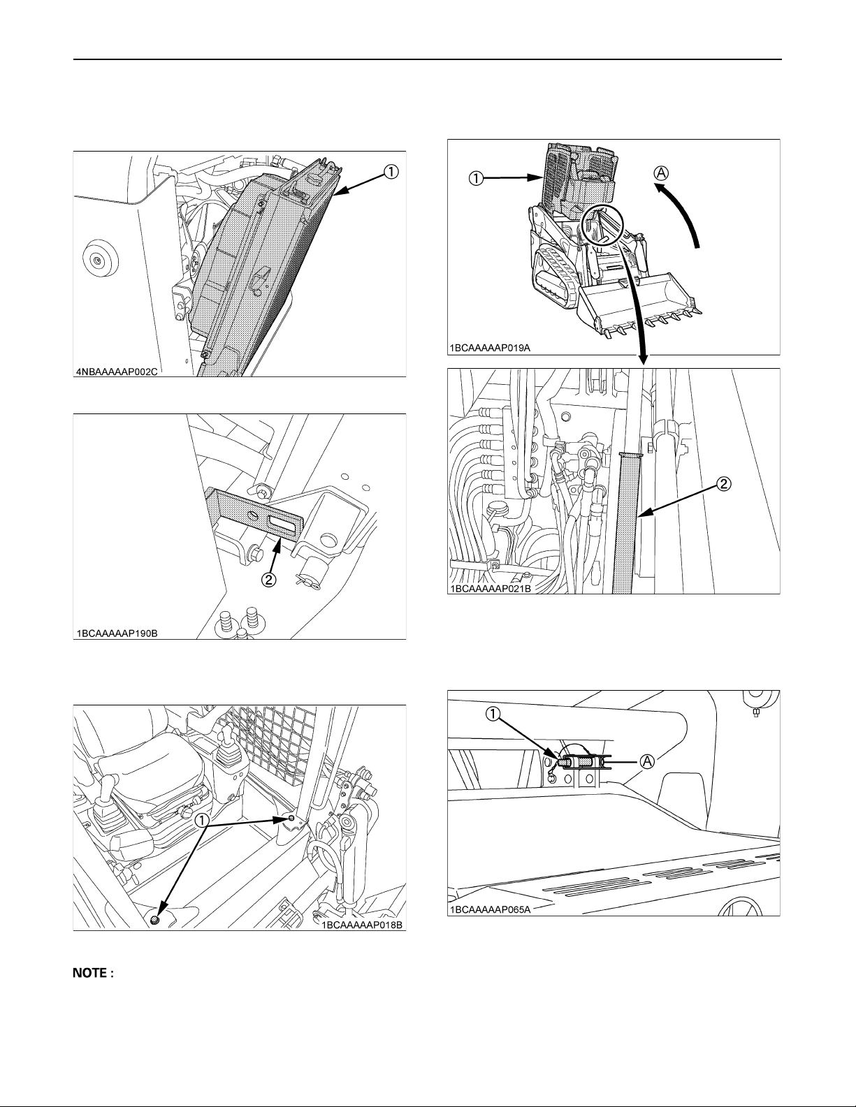
1. Open the rear and upper bonnet (1) (3).
AInsert the pin (2) into the locked position (A) to fix the
rear bonnet.
(1) Bonnet (Rear)
(2) Pin (A) Locked position
(3) Bonnet (Upper)

5
2. Pull out the radiator (1) maximally, then set the stopper
(2).
3. Remove the 2 lock bolts (1) from front of the machine.
ASocket size: 24 mm
4. Slowly raise the cab (1) until the cab is all the way up
and the latching mechanism (2) engages.
5. Insert the stopper pin (1) into the locked position (A) to
fix the cab.
(1) Radiator
(2) Stopper
(1) Lock bolt
(1) Cab
(2) Latching mechanism
(A) Raise
(1) Stopper pin (A) Locked position

6
B) Disassembly
1. Disconnect the fuel tube (1) from the separator (2).
2. Disconnect the fuel tube (1) from the shut off valve (2).
3. Disconnect the air vent hose (1) from the shut off valve
(2).
4. Disconnect the fuel tube (1) from the fuel filter (2).
Remove the clamp (3) from the guide (4).
5. Disconnect the fuel tube (1) from the fuel filter (2).
(1) Fuel tube (fuel tank - separator)
(2) Separator
(1) Fuel tube (valve - return)
(2) Shut off valve
(1) Air vent hose (valve - fuel pipe)
(2) Shut off valve
(1) Fuel tube (fuel filter - return)
(2) Fuel filter
(3) Clamp
(4) Guide
(1) Fuel tube (fuel filter - supply pump)
(2) Fuel filter

7
6. Disconnect the electrical connectors (2) of the fuel
filter (1) and the fuel pump.
7. Remove the bracket (3).
ADon't remove the separator, the fuel pump, the shut off
valve, and the fuel filter from the bracket (3) on this
step.
ATake care not to drop the bracket, when removing the
bolts.
AThe bolts (1) (2) will be reused.
(1) Fuel filter
(2) Connector
(1) Bolt
(2) Bolt
(3) Bracket

8
8. Disconnect the fuel tube (1) from the engine.
9. Disconnect the fuel tube (1) from the common rail (2).
10.Disconnect the fuel hose (1) from the supply pump (2).
11.Remove the clamp (3) of fuel tube (1) from the stay (2).
12.Disconnect the fuel tube (1) from fuel tank (2).
(1) Fuel tube (engine - return)
(1) Fuel tube (common rail - return)
(2) Common rail
(1) Fuel tube (fuel filter - supply pump)
(2) Supply pump
(1) Fuel tube (fuel filter - supply pump)
(2) Stay
(3) Clamp
(1) Fuel tube (tank - return)
(2) Fuel tank

9
13.Remove the fuel tube (1) from the stay (2). 14.Remove the fuel tube (1) from the stay (2) (3).
(1) Fuel tube (fuel filter - return)
(2) Stay (1) Fuel tube (cock - fuel pipe)
(2) Stay
(3) Stay

10
15.Remove the cap (1) and the pipe (2).
AThe cap (1) and the bolts (3) will be reused.
16.Remove the clamps (2) and the fuel hose (1).
AThe clamps (2) will be reused.
C) Sub assembly
1. Install the fuel filter (4) and the stay (3) to the bracket
(1).
2. Disconnect the fuel tubes from both ends of the fuel
pump (2) removed on step B)-7, then remove the fuel
pump (2) from the bracket (1).
AThe fuel pump (2) and the bolts (3) (4) will be reused.
(1) Fuel cap
(2) Pipe
(3) Bolt
(1) Fuel hose
(2) Clamp
Tightening torque (2) Bolt
24 to 27 N-m
2.4 to 2.8 kgf-m
18 to 20 ft-lbs
(1) BRACKET (FILTER, 1) (V0621-9861 )
(2) BOLT (01125-50825)
(3) STAY (HOSE CLAMP) (V0621-9863 )
(4) FILTER, ASSY (FUEL) (V0631-5168 )
(1) Bracket
(2) Fuel pump
(3) Bolt
(4) Bolt
(5) Band

11
3. Install the fuel tube (2) (3) to the fuel pump (1).
AWhite mark (A) on the fuel tube (2) should be on the
opposite side of the fuel pump installation face.
AConnect the plastic clamp (4) side of the fuel tube (3)
to the fuel pump (1) as shown in the illustration.
4. Install the fuel pump (1) to the bracket (2).
APass the fuel tube (5) through the hole of the bracket
(2).
(1) Fuel pump (reuse)
(2) FUEL TUBE, ASSY (V0621-9866 )
(3) FUEL TUBE, ASSY (500) (V0621-9865 )
(4) Plastic clamp
(A) White mark
Tightening torque
(3) M8 bolt
24 to 27 N-m
2.4 to 2.8 kgf-m
18 to 20 ft-lbs
(4) M6 bolt
9.81 to 11.2 N-m
1.00 to 1.15 kgf-m
7.24 to 8.31 ft-lbs
(1) Fuel pump
(2) Bracket
(3) M8 bolt (reuse)
(4) M6 bolt (reuse)
(5) Fuel tube

12
5. Install the fuel tube (2) to the fuel filter (1).
6. Insert the clamp of the fuel tube (1) to the stay (2).
AMake sure that the clamp (3) does not come off.
7. Connect the fuel tube (2) (4) to the separator (1).
Install the connector (3) to the fuel tube (2).
Then insert the plugs (5) to the connector (3) to stop
fuel leak.
AThe plugs (5) will be removed later before connecting
the connectors (3) to other fuel tube on the step D)-5.
(1) Fuel filter
(2) Fuel tube
(1) Fuel tube
(2) Stay
(3) Clamp
(1) FILTER, ASSY (SEPARATOR) (V0631-5186 )
(2) FUEL TUBE, ASSY (200) (V0621-9864 )
(3) CONNECTOR (HOSE) (3C131-4246 )
(4) TUBE, FUEL (09664-60400)
(5) Plug (male and female)

13
D) Installing new parts
1. Install the new bracket (2) to the place where the
original bracket removed on step B)-7.
2. Install the bracket (2) (3).
3. Install the separator (3) to the bracket (1).
ASet the detent protrusion (4) of separator (3) to the
bracket (1).
Tightening torque (1) Bolt
24 to 27 N-m
2.4 to 2.8 kgf-m
18 to 20 ft-lbs
(1) BOLT (01125-50825)
(2) BRACKET (FILTER, 2) (V0621-9862 )
Tightening torque (1) Bolt
24 to 27 N-m
2.4 to 2.8 kgf-m
18 to 20 ft-lbs
(1) Bolt (reuse)
(2) Bracket
(3) Bracket
Tightening torque (2) Bolt
48 to 55 N-m
4.8 to 5.7 kgf-m
36 to 41 ft-lbs
(1) Bracket
(2) BOLT (01135-51080)
(3) Separator
(4) Detent protrusion

14
4. Connect the fuel tube (2) to the separator (1).
5. Connect the fuel tubes (1) (2) with the connector (3).
6. Install the wire harness (1) to the bracket (2).
7. Connect the connector to the wire harness.
7-1. Connect the connector of separator (1) to the
wire harness (3).
7-2. Connect the connector (2) of fuel pump (1) to the
wire harness (3).
(1) Separator
(2) Fuel tube (separator - fuel pump)
(1) Fuel tube (separator - connector)
(2) Fuel tube (fuel tank - connector)
(3) Connector
(1) W/H (CONVERSION, 2, WS-WH) (V0621-9869 )
(2) Bracket
(1) Separator
(2) Connector
(3) Wire harness
(1) Fuel pump
(2) Connector
(3) Wire harness

15
8. Clamp the wire harnesses.
8-1. Clamp the wire harness (1) of the fuel pump to
the clamp position (3) of the bracket.
8-2. Clamp the wire harness (2) of the separator to
the clamp positions (4) of the bracket.
9. Prepare the fuel tube assy (1).
10.Connect the fuel tube (2) to the fuel filter (1).
AConnect the D part of the tube. (See the step 9.)
11.Clamp the fuel tube (1) to the stay (2).
(1) Wire harness (fuel pump)
(2) Wire harness (separator)
(3) Clamp position (wire harness of fuel pump)
(4) Clamp position (wire harness of separator)
(1) FUEL TUBE, ASSY (RETURN) (V0621-9868 )
(A) To the fuel tank
(B) To the engine common rail
(C) To the fuel return from engine
(D) To the fuel filter
(1) Fuel filter
(2) Fuel tube (return)
(1) Fuel tube (return)
(2) Stay

16
12.Connect the fuel tube (2) to the fuel tank (1).
AConnect the A part of the tube. (See the step 9.)
13.Clamp the fuel tube (1) to the stay (2).
14.Connect the fuel tube (2) to the fuel pipe (1) of the
engine.
AConnect the C part of the tube. (See the step 9.)
APass the fuel tube (2) under the SP hose (3).
15.Connect the fuel tube (2) to the common rail (1) of the
engine.
AConnect the B part of the tube. (See the step 9.)
APass the fuel tube (2) under the SP hose (3).
(1) Fuel tank
(2) Fuel tube (return)
(1) Fuel tube (return)
(2) Stay
(1) Fuel pipe
(2) Fuel tube (return)
(3) SP hose
(1) Common rail
(2) Fuel tube (return)
(3) SP hose

17
16.Connect the fuel tube (2) to the fuel filter (1).
AConnect the fuel tube (2) of the yellow tape side to the
fuel filter (1).
17.Connect the fuel tube (1) to the supply pump.
APass the fuel tube (1) under the fuel tube (2).
(1) Fuel filter
(2) FUEL TUBE, ASSY (770) (V0621-9867 )
(fuel filter - supply pump)
(1) Fuel tube (fuel filter - supply pump)
(2) Fuel tube (fuel filter - return)

18
18.Clamp the fuel tube (1) to the stay (2).
19.Clamp the fuel tube (2) by the cord band on the fuel
tube (1).
ACut the cord band leaving 5 to 10 mm.
20.Install the fuel pipe, the fuel hose, and the fuel cap by
the steps reverse from B)-15 to B)-16.
AUse the new parts below for the pipe and the hose.
(1) HOSE (FUEL) (V0511-5118 )
(2) PIPE (FUEL) (V0511-5117 )
21.Lower down the cab and make the maschine to the
first state by the steps reverse from A)-1 to A)-5.
22.Replace the label.
23.Start the engine, then check there is no fuel leak.
ASee "PURGING OF THE FUEL SYSTEM" in "OTHER
CHECKS AND REPLACEMENTS" section in the
Operator's Manual.
(1) Fuel tube (fuel filter - supply pump)
(2) Stay
(1) Fuel tube (fuel filter - supply pump)
(2) Fuel tube (fuel filter - return)
(A) 5 to 10 mm
Tightening torque Bolt
48 to 55 N-m
4.8 to 5.7 kgf-m
36 to 41 ft-lbs
(1) LABEL (MAINTENANCE) (V0521-5756 ) (English)
or
LABEL (MAINTENANCE, FR) (V0521-5956 ) (French)
Table of contents
Popular Water Filtration System manuals by other brands

HYDAC International
HYDAC International OF 5 C Operating and maintenance instructions

Thermo Scientific
Thermo Scientific Barnstead Pacific RO 3 operating instructions

Oase
Oase Bitron C operating instructions

Clarke
Clarke CAT186 Operating & maintenance instructions

Coway
Coway P-07FR user manual

Vetus
Vetus Sapro Installation instructions and operation manual

Atlantic Ultraviolet
Atlantic Ultraviolet Mighty Pure MP13A owner's manual

Pentair
Pentair Fleck 5800 XTR user guide

Delta Water Engineering
Delta Water Engineering PFS-M Installation & operating guide

AQUAPHOR
AQUAPHOR RO-101S owner's manual

AquaCo
AquaCo SYS -ROCOMP manual

Premier
Premier EZ-RO 4 Installation, operation and maintenance manual