Kuhling&Kuhling HT500 User manual

Operating manual HT500
The high-resolution 10“-TFT touchscreen mounted at the front panel enables direct operation of the
HT500.
This manual describes the initial commissioning of the 3D Printer after installation, the operation via
the RepRapOnRails operating software and the all manual operating tasks that must be performed
during normal day-today use.
RepRapOnRails Software version lists
v2.2.0 (current)
Starting the 3D Printer
There are two possible states from which to start the 3D Printer: “switched off” and in “standby”.
Either way starting the 3D Printer is a one-button-only procedure. After the boot sequence the
operating screen starts with the Print screen in IDLE mode.
Switching on
If the 3D Printer is switched off via the main
switch at the rear cover (position <0>) toggle
the switch to <I> (ON).
The 3D Printer will boot automatically.

It may take a few minutes until the touchscreen
has fully loaded the operating screen - wait
patiently without interfering.
The first screen will be the Print screen with the
(empty) print-job queue and the top-left status
message displaying Idle.
Powering up the 3D Printer.
Waking from standby
If the 3D Printer has been shut down via the
touchscreen and set into standby mode (see
section Print screen), press the wake button at
the front cover. The light ring of the button lights
up and the 3D Printer boots automatically.
Waking the 3D Printer from standby.
Graphical User Interface (GUI)
Menu selection of the RepRapOnRails operating software.
The start-up Print screen provides all basic operating functions.
The Configuration menu enables the operator to preselect temperature profiles for the extruders
and the print bed and build chamber more directly which simplifies preheating and priming according
to current needs.
Setup offers the operating wizards for guided day-to-day functions.
More advanced features such as program-independent operation of the axes can be found on the
Expert control screen which also provides direct setting of the extruder temperatures and test

extrusion.
The Log menu contains the history of machine code input and output as well as the keyboard for
direct input of operating instructions.
The following paragraphs provide detailed information of the software's operating screens and explain
the specific functions.
Additional information for the preparation of print jobs can be found in Tips and tricks and the manual
of the slicing software.
[Print] screen
After starting the HT500 the Print screen will appear as the start-up screen. Here you activate the 3D
Printer and start the print jobs previously uploaded to the queue via the web interface.
Print screen (descriptions may apply to other screens as well if not explicitly given there)
No. Description Content/Function
1 Status message Idle: apparatus is waiting for next user input
Printing: apparatus is busy printing
2 Menu selection
Select the operating menu and mode:
Print represents the main production mode
Configuration allows choosing material based temperature
profiles for each extruder and bed/chamber
Setup provides wizards for different preset operating
procedures
Expert Control provides access to motors and direct
temperature control
Log represents the communication history of microcontroller,
BeagleBone Black, and touchscreen
3 Queue List of uploaded print jobs sorted by time/date (oldest first);
estimated time required for printing the respective job.

No. Description Content/Function
4 Temperature/profile overview
Displays current and set temperature of each extruder, print
bed and build chamber as well as the selected material profiles
(see Configuration). Temperatures colored red are set and
currently being actuated.
5 [Emergency STOP] button
see also
→ Emergency stop
→ Safety information in the Manual
6 [Shut-down] button Tap to shut down the 3D Printer properly.
7 [Build Chamber ON/OFF] button Tap to activate/deactivate drives and heaters after start-up.
8[Preheat Chamber/Bed ON/OFF]
button
Tap to activate/deactivate preheating of the build chamber/print
bed according to the settings made under Configuration.
9 [delete] button Tap to delete the respective print job from the queue.
10 [print] button Tap to start the respective print job.
11 Browse buttons Use [Previous], [Next] and [page number] to browse the print
job list.
Starting print jobs
Tap the [print] button next to a print job in the queue to start the print job. You will be asked to
confirm that all preparations for the print job have been performed. Tap [OK, Start Print] to definitely
begin printing or [Cancel] to return to the queue.
“Ready to print?” query
No. Description Content/Function
1 Checklist Please make sure that all displayed requirements have been met before
proceeding.
2 [OK, Start Print] button If all preparations have been made, tap to proceed.
3 [Cancel] button Tap to abort if any requirements has not been met.

After confirmation the HT500 starts processing the print job and the status message changes to
Printing. All other menus are deactivated during a print. The print job name, the current progress, and
the estimated remaining time are displayed and the [Abort Print] button is active.
Print status screen (top half only).
No. Description Content/Function
4 Print job name The name of the slicing file uploaded to the queue.
5 Countdown Displays the estimated remaining time (calculated from the G-
code).
6 Progress bar Indicates the progress of the print job graphically.
7 [Pause/Resume Print] button Allows interrupting a print job for interference and subsequent
resumption.
8 [Abort Print] button Tap to abort a print job.
Pause function
The pause function was built in for the case that a print job needs to be interrupted and later resumed
for other reasons than “out-of-filament” (see below).
Interrupting the print with the pause function.
After tapping the [Pause Print] button, the printer keeps printing until the cache is empty. This may
take a few minutes, according to the complexity of the current g-code. Afterwards, the print bed is
lowered into its home position, the extruders are turned off and the print head moves to the
maintenance position.
Now you have access to the Expert Controls and some of the Setup functions to adjust whatever
might be necessary.

Continuing the print after pause.
To continue printing tap [Resume Print] (replaced [Pause Print]). Print bed and extruder head move to
their last position and after re-heating the extruders the print seamlessly continues.
Finishing a print job
There are two ways to finish a print job: automatic finish after completion or abortion by the operator.
After regularly completing a print job all axes are moved to their home position and the extruder
heating resistors are switched off.
If you need to abort a print job because the outcome does not meet expectations for example or
mechanical problems appear during the print, tap the [Abort Print] button. The system will then print
the last G-code information from cash and move the print table and the extruder head to their home
positions afterwards.
Either way, the 3D Printer returns to idle mode and displays a status message and a request how you
wish to continue. Simply tap the respective button on the screen to proceed.
After standstill of all drives you can remove the print bed and take off the model.
Print job finished.
No. Description Content/Function
9 [Keep in Queue] Returns to the Print menu.
10 [Print Again] Immediately restarts the current print job.
11 [Delete Printjob] Deletes the finished print job from the queue without confirmation and returns
to the Print menu.
Switching off the 3D Printer
NOTICE

Switch off the 3D Printer via the power button without turning it into standby may cause damage of
the heating elements and neighboring components due to residual heat.
The cool-down performed during shut-down ensures that the fans are only switched off after the
heating elements could shed all residual heat.
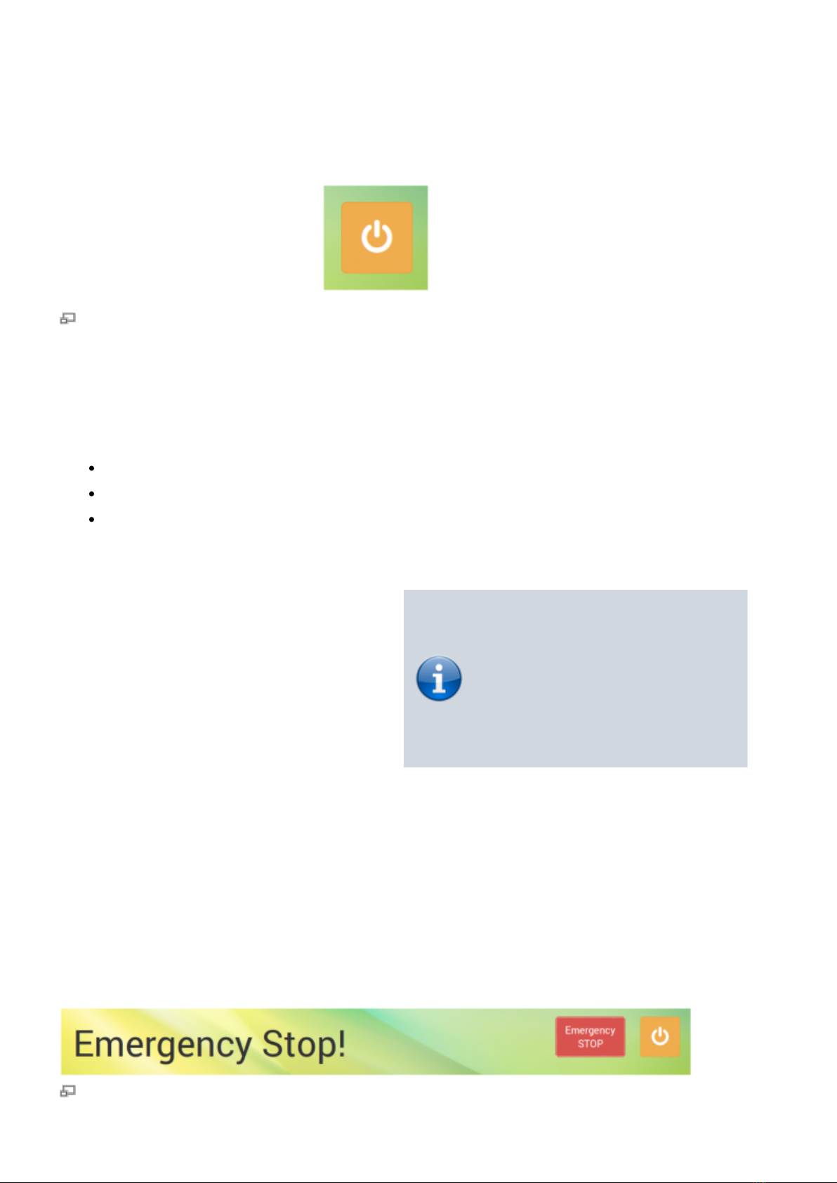
Always use this button for regular shutdown.
For switching the HT500 into standby tap the shut-down button. The system will then perform the
cool-down sequence for safety reasons before deactivating the preheating and the build chamber.
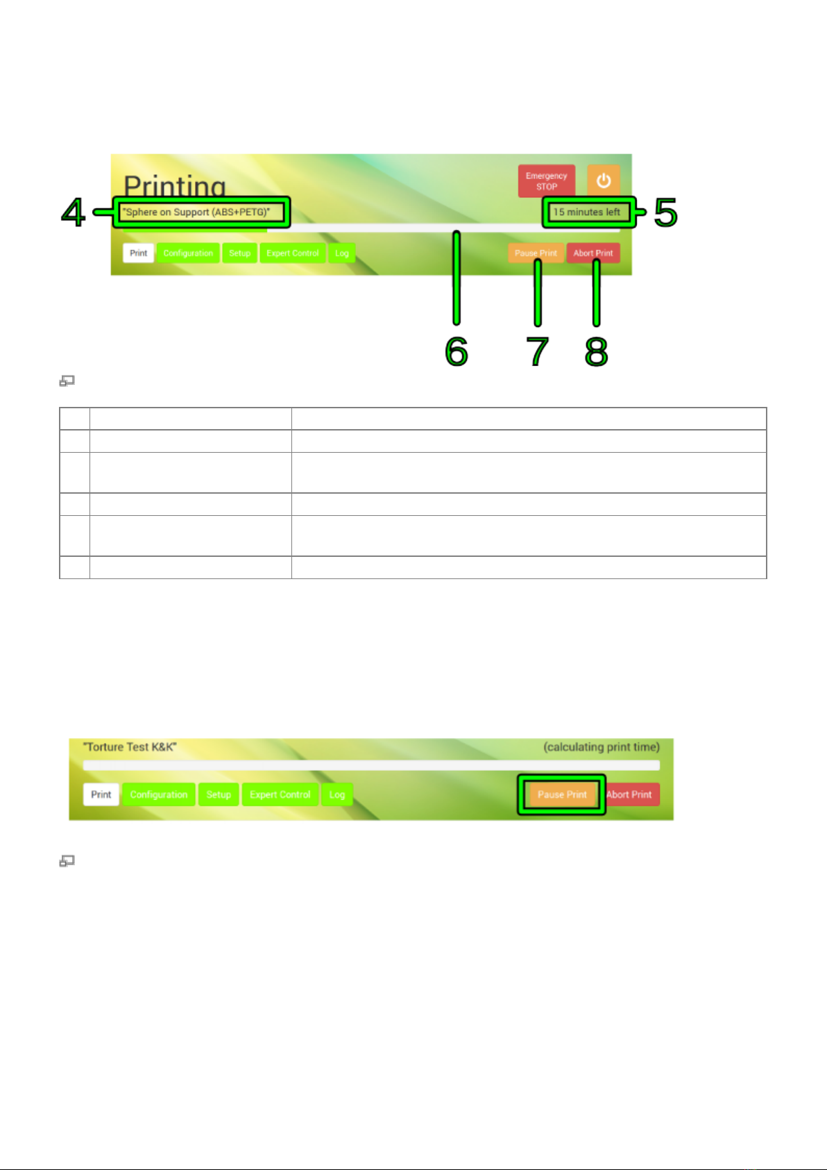
The 3D Printer is in standby mode when:
the screen turns black,
the illuminated ring of the wake button dims,
the build chamber lighting switches off.
To wake the machine from standby see Starting the 3D Printer.
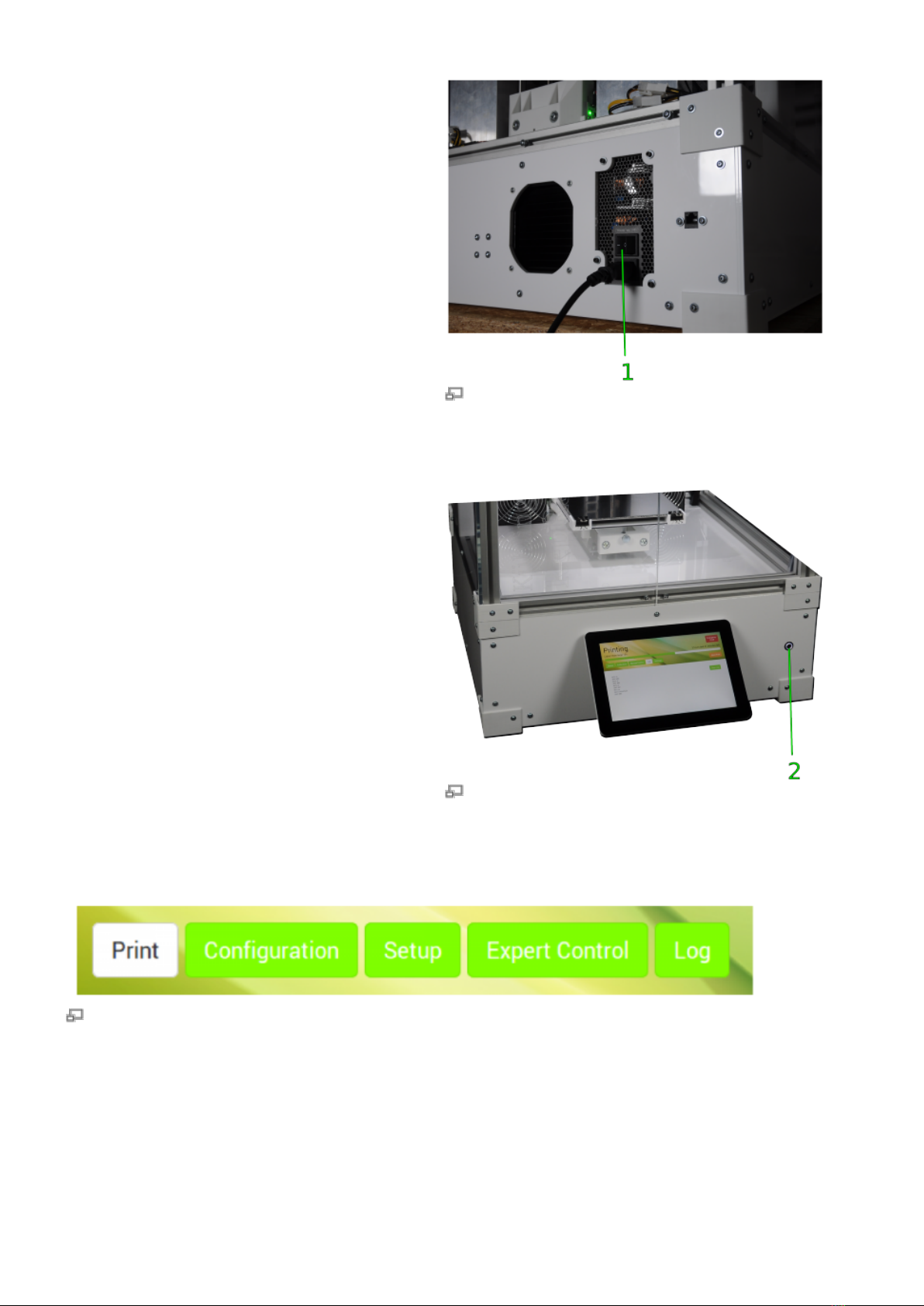
For completely shutting down the 3D Printer,
perform the procedure described above and set
the main switch at the rear cover to <0> (OFF)
afterwards. The 3D Printer is now powered off
and the green status indicators of the limit
switches darken.
To reactivate the 3D Printer see Starting the 3D
Printer.
INFO
For day-to-day use, the power
supply should stay connected to
mains power (main switch in
position <I> (ON).
Emergency stop
NOTICE
The emergency stop function does not provide a cool down sequence. Do not use the emergency
stop button to abort current print jobs, as this may lead to damage of the 3D Printer due to
uncontrolled heat accumulation. Do not use the main switch as an emergency stop button. You risk
loosing or corrupting data.
Status display after triggering the emergency stop. The 3D Printer returns to IDLE state after a short

time. The emergency stop is written into the log-file.
When the emergency stop is triggered:
The microcontroller board is reset, all movement of the axes stops, lights, heaters and fans are
turned off. The status indicator displays Emergency Stop! .
After a few seconds the microcontroller returns to Idle state.
The 3D Printer now is in a safe state for troubleshooting.
For repairing any defects of the electronic equipment or major mechanical damages shut down
the 3D Printer completely:
Open the Print screen.
Shut down the 3D Printer by tapping the [Shutdown] button and switching off the main switch
(<0> position) after the shutdown procedure has been finished.
NOTICE
Before restarting or reactivating the 3D Printer:
Make sure that the axes are in no collision position.
Make sure that the reason for the emergency stop has been detected and fixed, before
resuming production.
After troubleshooting or if the reason for the emergency stop was minor and you want to continue
production:
Remove the print bed from the build chamber and replace or clean it before further use.
Restart the 3D Printer (if necessary).
Open the Print screen.
Switch on the build chamber. The 3D Printer will run the homing routine.
You can now resume normal operation.
[Configuration] screen
The Configuration menu is a new feature that enables you to preselect material-specific temperature
profiles for each extruder and, in combination, the print bed/build chamber. The latter was developed
to make preheating and leveling more precise with regard to different material settings. The
according profiles can be set up at the web interface setup menu.

GUI Configuration screen with temperature profile selection.
No. Description Content/Function
1 Left extruder profile selection The currently selected profile is displayed.
Tap [Select] to open the list of available filament profiles or
[Clear] to delete the active profile.
2Right extruder profile
selection
3 Bed/chamber profile selection
The currently selected profile is displayed.
Tap [Select] to open the list of available filament profiles or
[Clear] to delete the active profile.
After selection of a profile, deactivate the preheating function in
the Print menu (touch button no. 8) and activate it by tapping the
button again to apply the settings.

The list of filament temperature profiles of the configuration menu. More profiles can be added via the
web-interface.
After opening the list, tap [Set] to choose a profile for the selected component. The profile is set and
the screen returns to the prior menu.
To activate the selected profile open the Print screen and first deactivate, then re-activate the
chamber/bed preheating.
The selected profiles are displayed in the footer of the GUI on every screen.
The selected profiles are displayed in the footer
of every screen in the order Current and Target
(= set) temperature. While aiming for a target
temperature, both values are highlighted red.
When displayed gray, the temperature value is
either not set or currently not triggered.
If no filament profile is activated for an extruder,
the default temperature is 180 °C.
INFO
Observe that the temperature
shown in the footer is measured at
the hot end heater and may be 5 -
10 °C lower at the nozzle tip.
See section Extrusion temperature
in the knowledgebase for
information on finding the suitable
extrusion temperature.
[Setup] screen
The Setup menu displays walkthrough instructions (wizards) for different operations needed during
daily operation, initial commissioning, servicing and troubleshooting. If you choose one of the wizards,
a step-by-step guide will provide all necessary information for completing the respective task.
This screen also provides system information and the web address needed to connect to the 3D
Printer via the network.

Wizard selection on the setup screen. Beginning with ReRapOnRails v1.3.0, the nozzle change wizard
has been replaced by the backlash calibration wizard.
No. Description Content/Function
1
Wizards for daily
operation
Different wizards for
different tasks; needed
to keep your 3D Printer
up and running.
Print Bed Leveling
Ensures that print bed and nozzle tip are evenly distanced at
every point of the surface.
→ tips
Unload Filament
False removal of filament from the supply system can damage
the limit switch in the feed unit. Follow the given instructions
when filament must be removed.
→ additional information
Load Filament
False insertion of filament can damage the 3D Printer or lead to
coiling of the filament and thereby ruining the print. Follow the
given instructions when filament must be refilled or changed.
→ additional information
Prime Extruders
After changing/refilling filament or subsequent to nozzle change
the extruders must be primed to remove enclosed air from the
nozzle tip.
→ additional information

No. Description Content/Function
2
Calibration wizards
These wizards are
needed during
commissioning, during
change of material and
other more rarely tasks.
Calibrate Extrusion
When printing material with other properties than before, it
might be necessary to adjust the throughflow of the nozzle. To
find the correct Extrusion multiplier to be entered in the
Filament settings of Slic3r, run this wizard. Also regard the
description given in the respective initial commissioning
section.
Calibrate Extruder Offset
This function is needed for dual extruder prints. To teach the
offset distance between the nozzle tips in X- and Y-direction,
run this wizard.
Calibrate Axes Backlash
This function replaces the backlash calibration procedure
described in the Service Guide.
No. Description Content/Function
3 Web Interface URL Needed to connect to your HT500 via the network
→ additional information
4 Version numbers
The valid version numbers of your HT500's hardware, the installed
RepRapOnRails software and the microcontroller firmware for your
information. Please provide these numbers for identification in case of service
requests.
Changing the filament
When the filament limit switch at the filament supply registers the end of the filament strand on the
spool, the 3D Printer stops automatically and signals lack of material at the touchscreen.
If you want to remove the filament for other reasons (e.g. to use a differently colored material), the
following description applies also.
Required tools

diagonal cutters
Refilling
If you want to continue printing with the same type of plastic, the change of the filament spool is
quite easy. You have to manually remove remaining filament from the supply hose, change and, if
need be, adjust the spool carriers and insert the new strand.
Go to the Setup menu and start the [Unload Filament] wizard and follow the on-screen1.
instructions.
Then open Setup menu again, and follow the [Load Filament] wizard.2.
Material change
If you want to continue printing with another
type of plastic (e.g. PETG instead of ABS), the
change of the filament spool becomes a little bit
more complex since you have to change the
extruder nozzle barrel also.
INFO
Using the same extruder nozzle
barrel for materials with different
properties may lead to clogging of
the nozzle tip due to coking or
sooting.
Kühling&Kühling recommend either
thorough cleaning of the extruder
nozzle barrel with a suitable solvent
and pipe cleaners or using a single
barrel for every type of material.
Unload the current filament as described1.
in Refilling.
Subsequent to unloading you have to2.
change the extruder nozzle barrel as
described in the Service guide.
Afterwards, install (and adjust) the new3.
filament spool, run the [Load Filament]
wizard and the [Priming] wizard.
INFO
Make sure to choose the
appropriate filament profile from
the material database. If you have
not installed the adequate profile
yet, do so by following the
instructions given below.
Adjusting the spool carriers
Required tools
Allen wrench #2.5

Procedure
If you want to use a different filament spool
diameter (less or more material), you have to
adjust the spool carrier position.
INFO
With an appropriate Allen key you
can carry out the following steps
without removing the filament
spool.
Use the Allen key to loosen the fixing
screws of the carrier.
Loosening the fixing screws of spool carriers.
Slide the carrier to or away from the
filament inlet to a position that leaves
approximately 1 cm between the spool's
outer rim and the limit switch. Make sure
that the filament enters the inlet at an
angle of 85-90°.
Refasten the fixing screws.
Admissible distance and inlet angle.
[Expert Control] screen
NOTICE

The Expert Control menu should be used by skilled operators only. It has been designed for test and
troubleshooting purposes. Persons unfamiliar with the 3D Printer must not use the functions provided
here.
The positions of the extruder head and the print table are not compared during manual operation.
Incautious operation may lead to massive damage of the extruder head and the print bed.
Be careful not to crash the print table and the extruder head.
For maintenance and test reasons, after a crash or to reduce lead times, e.g. if you still need to work
on a print file but want the
3D Printer to be ready for operation, manually moving the motors or preheating the build chamber
and the print table may be necessary or advantageous.
Expert Control screen
No. Description Content/Function
1Drive control -
negative direction
Moves every axis individually once for every tap in negative direction,
according to the selected step width.
2[Printhead
Maintenance Position]
Tap to move the extruder head into a preset position in the upper center
of the build chamber directly in front of the doors where it is easily
accessible for maintenance purposes.
3 Homing buttons Tap to separately or simultaneously move the axes to their starting
positions.
4Drive control -
positive direction
Moves every axis individually once for every tap in positive direction,
according to the selected step width.
5Extruder temperature
control
Enables directly setting the temperature and extruding filament for one
extruder at a time (see the chapter "Extrusion temperature" in the
“Material” section of the knowledgebase).
[Log] screen
All communication between touchscreen, BeagleBone Black and microcontroller is stored and

displayed on the log screen. Print job statuses are stored also.
Direct G-code programming can be effected via the G-code input field.
The log screen provides additional information about sent and received G-code commands and the
possibility of directly influencing the 3D Printer via G-code command input.
No. Description Content/Function
1 History list
communication history sorted top down by date and time¹
SENT: BeagleBone Black to microcontroller
RECV: microcontroller to BeagleBone Black
2 Browse buttons Use [Previous], [Next] and [page number] to browse the history.
3 G-code input field Enter G-code lines here and [Send] them.
¹ The time is stated in universal time coordinated (UTC) notation so do not wonder if does not match your local time.
NOTICE
The G-code input field is an advanced feature and requires sound knowledge of GCODE programming.
Inappropriate G-codeing may damage the 3D Printer massively.
The web interface
The web interface provides the communication between your PC and the 3D Printer. Uploading print
job GCODES to the 3D Printer and creating temperature profiles are the main functions.
You can also check system's information and settings, install firmware updates and download the
LOG-file for troubleshooting purposes.
To open the web interface enter the web interface URL into the address line of your internet browser.
You can find the web interface URL on the Setup screen of the GUI.

First Steps
This is the start screen of the web interface. Here you find a direct link to the online documentation.
In the header of this and all following screens you find live information about the currently active print
job, the remaining print time and the status of the 3D Printer.
First Steps screen of the web interface.
Queue
Print jobs are managed via the Queue. Here you can upload GCODES, individaully name, edit, or
delete them.
The Queue contains list of uploaded print jobs in a top-down order with the last upload first.

Uploading print jobs to the Queue.
To create a print job:
Click [Add Printjob].1.
Enter the identification (name or number or the like) of the print job in the text field1.
Name. This will be shown in the status field during the print job is conducted.
If required, add additional information via the text field Note.2.
Click [Browse] to select a GCODE from the valid directory.2.
Click [Add] to upload the selected file to the printer. The print job is added to the list as the first3.
entry.
Click [Cancel] to abort the procedure.
The print job is now available for printing on your HT500 and can be selected directly for printing via
the touchscreen controller on the 3D Printer.
Editing or deleting print jobs from the web interface queue.
To subsequently renaming print jobs or altering information click on [edit] and use the text1.
fields.
To delete a print job from the queue click on [remove] and acknowledge the query by clicking2.
<OK>.

Setup
In the Setup menu temperature profiles for materials and print bed/chamber can be managed, system
information can be viewed, firmware updates can be conducted and, EEPROM-data can be set.
Temperature profiles on the Setup screen of the web interface.
System information that can also be found on the Setup screen of the GUI. Please always provide
these in case you contact the Technical Support.
Installing a new Arduino firmware - which may only be done when explicitely requested by
Kühling&Kühling - is done via the Setup menu. Find additional information in the Upgrade section.

The EEPROM editor may only be used by experienced users or if explicitely stated in this manual and
strictly within the specified parameters. Its main purpose is helping the Technical Support during
troubleshooting.
Creating temperature profiles
During a print job all necessary temperature data are provided by the respective G-code. For priming
the extruders outside a print job the temperature setting required for extruding a material is provided
by the Filament profiles.
Similarly, precise print bed leveling needs defined bed and chamber temperatures according to the
printed material before a G-code is executed. These settings are provided by the Chamber/Bed
Preheating Profiles.
Filament profile setup via the web interface.
To create a filament profile open the web interface of your 3D Printer, choose the Setup menu and:
Select Filament Profiles and click [Add Profile] to set material properties.1.
Enter the material Name in the according input field.1.
Enter the Extrusion Temperature in °C in the according input field.2.
Click [Add] or press <Enter> to save the settings. The new filament profile is added to the list,2.
Other manuals for HT500
2
Table of contents
Other Kuhling&Kuhling 3D Printer manuals