KUHN MDC User manual

No 95738 B.GB - 01. 2005
OPERATOR'SMANUAL
MDC
Application rate monitoring
system
for VENTA

DEAR OWNER,
In buying a KUHN machine you have chosen wisely. Into it have gone years of thought,
researchandimprovements.Youwillfind,ashavethousandsofownersallovertheworld,that
you have the best that engineering skill and actual field testing can produce. You have
purchased a dependable machine, but only by proper care and operation can you expect to
receive the performance and long service built into it.
This manual contains all the necessary information for you to receive full efficiency from your
machine.Theperformanceyougetfromthismachineislargelydependantuponhowwellyou
readandunderstandthismanualandapplythisknowledge.PleaseDONOTASSUMETHAT
YOU KNOW HOW TO OPERATE AND MAINTAIN YOUR MACHINE before reading this
manual carefully. KEEP THIS MANUAL AVAILABLE FOR REFERENCE.
YourKUHN dealerwillinstruct youonthegeneral operationofyourmachine. Heisinterested
that you get the best performance possible and will be glad to answer any special questions
that may arise regarding the operation of the KUHN machine.
Your KUHN dealer can offer a complete line of genuine KUHN service parts.
These parts are manufactured and carefully inspected in the same factory that builds the
machine to assure high quality and accurate fitting of any necessary replacements.
When ordering service parts it is important that you indicate the type of machine concerned
and its serial number.
Forthisreasonpleasecompletethemodelidentificationplatediagrambelowwiththerequired
information. This will provide you with an easy reference for future service parts orders.
ABOUT IMPROVEMENTS
KUHN iscontinuallystriving to improveitsproducts and,therefore,reserves the righttomake
improvements or changes when it becomes practical to do so, without incurring any
obligations to make changes or additions to the equipment sold previously.

2
TABLE of CONTENTS
A Description............................................................................................................. 3
B Summary of use .................................................................................................... 4
C Detailed description of the system...................................................................... 6
C 1 Electric power supply................................................................................... 6
C 2 Design.......................................................................................................... 6
D Work and display settings ................................................................................... 8
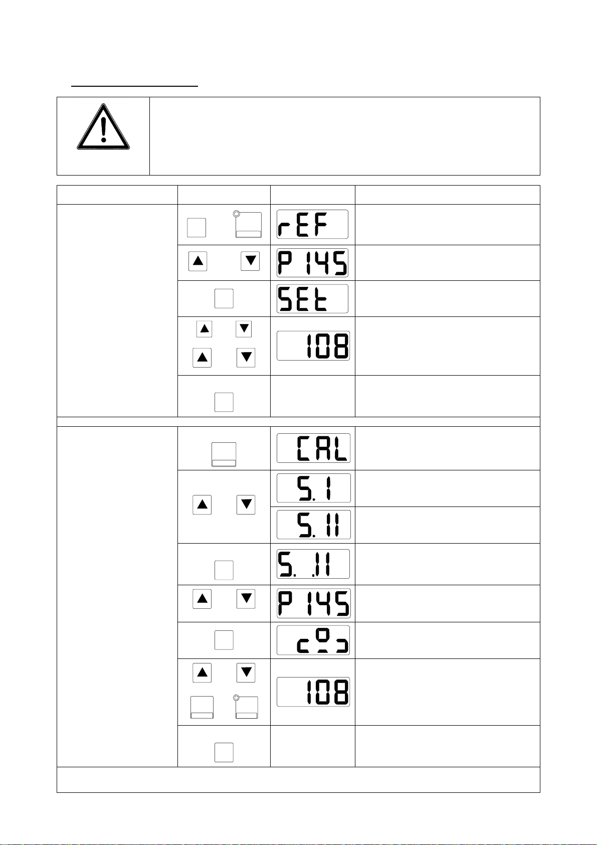
D 1 Setting the point of reference ...................................................................... 8
D 2 Opening calibration (flow control)................................................................. 9
D 2.1 Setting the seed type........................................................................ 9
D 2.2 Setting the opening......................................................................... 10
D 2.3 Flow control ................................................................................... 10
D 3 Programming the nominal application rate (100% )................................... 11
D 4 Adjustment to the nominal application rate (100%).................................... 12
D 5 Setting the application rate adjustment level.............................................. 12
D 6 Application rate adjustment in %................................................................ 12
D 7 Setting the null flow rate ............................................................................ 13
E Connection to a « Master » terminal (GPS mode)
E 1 Description................................................................................................. 14
E 2 Work and display settings.......................................................................... 15
F System adjustment and calibration .................................................................. 16
F 1 Adjusting the opening pulses...................................................................... 16
F 2 Adjustment of the opening limit points........................................................ 17
F 3 Screen test................................................................................................. 18
F 4 Rotation sensor test ................................................................................... 18
F 5 Motor and sensor pulse test....................................................................... 18
F 6 Setting the maximum amperage................................................................. 19
F 7 Setting the maximum functioning time under maximum amperage............ 19
G Trouble shooting guide..................................................................................... 20
H Symbols ............................................................................................................. 21

3
A Description
1
23 45
6
78
MDC
CAL
REF
kg / ha
+
-100%
F
SP STEP %
9
1 –Screen
2 –« Arrow » keys
3 –« Function » key
4 –« Plus » key
5 –« Flow control » key
6 –« Movement »display
7 –« Minus » key
8 –« 100% application rate » key
9 –Standard connection socket
2 «Arrow » keys ?? Modification of the value.
3 «Function » key ?? Sets system by pressing this key when switching
on.
?? Second function of keys when pressing this key
simultaneously.
?? Store the selected function by pressing and
holding
4 «Plus » key ?? Increase in % of the application rate.
?? Setting the application rate monitoring level (dual
function key).
5 «Flow control » key ?? Setting the seed type (small or large seeds).
?? Programming the opening for carrying out a flow
control .
?? Setting the null flow rate (dual function key).
6 «Movement »display ?? LED lights when metering unit rotates.
7 «Minus » key ?? Reduction in % of the application rate.
?? Setting the point of reference (double function).
8 « 100% application rate » key ?? Adjustment to the nominal application rate
(100%)
?? Programming the application rate (dual function
key)

4
B Summary of use
IMPORTANT
When moving the metering unit by more than 30 mm, rotate metering
unit to avoid crushing seeds !
When seeding in « small seed » position, the control box must also be
set on the « small seed »position!
Action Control Screen Result
Fand REF
-
Automatically goes to next screen
after 2 seconds
and
Metering unit moves to the required
opening
F
Automatically goes to next screen
after 2 seconds
or
or
Setting an opening position
Checking the open-
ing position
(task to carry out at
work begin, in case
of seed change, at
least once per day)
3 seconds
FStoring the opening
3 seconds
CAL
SP
Automatically goes to next screen
after 2 seconds
Setting « small seeds »
or
Setting « large seeds »
3 seconds
F
Storing the choice of seed type
or
Setting the metering opening ac-
cording to chart
F
Automatically goes to next screen
after 2 seconds
or
+
STEP % orREF
-
Entering weight in kg/ha
Calibration of the
seed type
Setting the opening
(flow control)
3 seconds
FStoring the collected weight
Programming the nominal application rate /ha !

5
Action Control Screen Result
Fand kg / ha
100%
Automatically goes to next screen
after 2 seconds
Automatically goes to next screen
after 2 seconds
or
+
STEP % ou REF
-
Setting the nominal application rate
(100 %) in kg/ha
Setting the nominal
application rate /ha
(100%)
3 seconds
F
Storing the nominal application rate
Fand +
STEP %
Automatically goes to next screen
after 2 seconds
or
Adjustment of the level to
5%, 10% or 15%
Setting the applica-
tion rate monitoring
level
3 seconds
FStoring the monitoring level
+
STEP % or REF
-
The application rate is adjusted of
the displayed level (max. ?60%)
The metering unit position is dis-
played for 2 seconds
alternately
The adjusted application rate and
the adjustment level are displayed
alternately.
Adjustment of the
application rate (in
%)
kg / ha
100%
alternately
Setting the nominal application rate

6
C System description
C 1 Electric power supply
The MDC control box is supplied by a 3 pin plug
(DIN 9680, IS
O 12369) connection onto the tractor
network
Pin number Wire colour Function
15 / 30 Brown + 12 Volt
31 Blue Mass
81 -Not used
1
2
3
15/30 31
82
C 2 Design
The MDC electronic monitoring system is com
posed
of a control box (1), a wiring harness (2) be
tween
the tractor and the machine, a sensor and a driving
motor.
The MDC control box is connected either by its 9-
pin
plug (3) in the cabin to the 9-pin plug (4) of the wir-
ing harness connector or on the 9-
pin plug (5) if
moved to the machine. The ele
ctric power supply is
made through plug (6).
The control box is protected by a fuse of 15 A (7).
Recommended distance of sensor (with regards
to the notched wheel metal stud)
Sensor Distance
From motor position 0,4 –0,8 mm
1
3
2
4
5
6
7

7
VENTA MDC connection plan

8
D Work and display settings
The following settings and displays are vital (bold) or can be made in view of the work to
carry out :
1) Setting the point of reference
2) Calibration of the opening (flow control)
3) Programming the nominal seed application rate (100%)
4) Adjusting the metering unit to the nominal seed application rate
5) Programming the seed application rate adjustment level
6) Distribution adjustment of the chosen seed application rate
7) Setting the null flow rate (in case of maintenance)
D 1 Setting the point of reference
Should their be a power cut during a motor manoeuvre or due to its removal, the point of
reference must be newly calibrated.
It must be checked at work begin, when changing the seed type or at least once a day!
Press key Fand key REF
-to recalibrate the point of reference:
The screen displays the theoretical point of reference: it must be
adjusted to an identical position corresponding to the current real
opening position of the metering unit.
+
STEP % or REF
-keys enable changing the metering unit opening position (for ex. : for an
easier reading of the graduation). This manoeuvre is not compulsory !
Press key F: the screen briefly displays . Now, modify with keys +
STEP % or
REF
-to obtain the required value.
Store this value by pressing Fkey for 3 seconds until the display
flashes briefly!
1) Metering unit position (ex. : 70)
1

9
D 2 Calibration of the opening (flow control)
Press for approx. 3 seconds key CAL
SP to carry out calibration for the flow control
(selection of the seed type, choice of opening for the flow control).
IMPORTANT
For seeding with the metering unit in « small seed » position
(rapeseed, clover, rye-grass,… i.e. with metering unit reduc-
tion slide engaged), the MDC must also be set on «small
seed » position if you do not want to risk damaging the me-
tering unit during work !
D 2.1 Setting the seed type
Use keys to select the seed type:
Small seed (clover, rapeseed, grass, etc.)
Large seed (wheat, barley, peas, horse beans, etc,)
Store this value by pressing Fkey for 3 seconds until the dis-
play flashes briefly!
The type of seeds memorized is briefly displayed on the screen:
Small seed (clover, rapeseed, grass, etc.)
Large seed (wheat, barley, peas, horse beans, etc,)

10
D 2.2 Setting the opening
The current value of the metering unit position is displayed:
Opening position
Select from the adjustment chart the required opening in order to carry out a flow
control. It depends of the seed type and the required application rate (ex. : rate re-
quired in wheat 180 kg/ha, opening position at 90).
Use key +
STEP % or key REF
-to reach the desired opening position.
IMPORTANT
When moving the metering unit by more than 30 mm, rotate
metering unit to avoid crushing seeds !
Press key Fto go onto the next step.
D 2.3 Flow control
After having selected the opening and pressed on key F
the
screen briefly displays the scale symbol :
You may now carry out the flow control (see seed drill operator’s manual).
Weigh the quantity collected during test, convert it in kg/ha and enter it using
keys .
Store this value by pressing Fkey for 3 seconds until the dis-
play flashes briefly!

11
The nominal seed application rate must now be programmed by pressing on key
Fand at the same time briefly on key kg / ha
100% .
NOTE : An alarm is displayed if the metering unit opening limits are reached when
setting the nominal application rate. The desired value cannot be reached, the screen
shows alternately the obtained seed application rate and the corresponding adjust-
ment level.
D 3 Programming the nominal application rate (100%)
To programme the nominal application rate (i.e. the average value or 100%) press
key Ftogether with key kg / ha
100% . The screen briefly displays
Use keys or +
STEP % or keys or REF
-to display the desired nominal
application rate in kg/ha.
Example of nominal seed application rate in kg/ha
Store this value by pressing Fkey for 3 seconds, the value is
stored when the display shows before switching to the
work screen!
Note: a message appears if the metering unit opening limits are reached when pro-
gramming the application rate, the maximum seed application rate which can be
reached will be displayed.
Alarm Point of Limit « small seed » reached
Alarm Point of Limit « large seed » reached

12
D 4 Adjustment to the nominal application rate (100%)
Press key kg / ha
100% to adjust the metering unit opening to the nominal application rate.
D 5 Setting the application rate monitoring level
The monitoring level in % can be adjusted by pressing key Ftogether with
key +
STEP % .
Use keys +
STEP % and REF
-to choose the adjustment level in steps of 5%, 10% or
15%.
Store this value by pressing Fkey for 3 seconds until the dis-
play flashes briefly!
D 6 Adjustment in % of the application rate at work
Use keys +
STEP % or REF
-to adjust the nominal seed application rate to a different
application rate.
The display alternately shows the application rate reached and
the current adjustment level :
The maximum seed application rate adjustment range is ± 60%
on condi
tion that the metering unit opening limit is not reached.
An alarm appears if the opening limits are reached, the maximum seed application
rate which can be reached and the corresponding adjustment level will show alter-
nately.
Alarm Point of Limit « small seed » reached
Alarm Point of Limit « large seed » reached

13
D 7 Setting the null flow rate:
This adjustment is specific to the seed drill type (mechanical or pneumatic) and is
only to be carried out when fitting the equipmentor should the MDC control box
be replaced.
The calibrations of the null flow rate (in small or large seeds) is carried out by press-
ing simultaneously on keys Fand CAL
SP .
Use keys to choose the one to programme. Press key Fand use keys
or +
STEP % REF
-to modify these values.
Value of the null flow rate in «small
seeds » for VENTA seed drills
Value of the null flow rate in «large
seeds » for VENTA seed drills
??
This programming must imperatively be made for SP1 and
SP2.
?? Store this value by pressing Fkey for 3 seconds until
the display flashes briefly!

14
E Connections with a « MASTER » terminal (GPS mode)
The standard connection plug enables connecting the MDC control box to a terminal.
This link enables monitoring the application rate within the field (Precision Farming).
The GPS positioning and the corresponding application rate are transmitted by the
«master » terminal to the MDC control box.
Depending on the « master » terminal, the MDC control box will transmit in return
information on the work achieved, to the « master » terminal. Information on the use
of the « master »terminal is indicated in its operator’s manual.
E 1 Description
Following terminals, fitted with a standard RS232 plug, can be connected using a
cable 0 Modem Sub D9 (female/female) for connection to the MDC control box. The
wiring plan in the cable can be checked at point C2.
PRO SERIES
(RDS) (AGROTRONIX) FIELD
OPERATOR
(WTK)
ACT
(MÜLLER /
CLAAS)
FIELDSTAR
(AGCO)
cable 0 Modem Sub D9 (fe-
male/female)
MDC Control box

15
E 2 Work and display settings
Prior to connecting the terminal and the MDC control box, select the connection
protocol in the « master » terminal.
This protocol is in one way the « language » which will enable communication be-
tween both control boxes. Refer to the « master » terminal operator’s manual to ad-
just this selection.
« Master » Terminal Connection protocol
PRO SERIES 8000 (RDS) Modus B, FIELDSTAR
AGRO PILOT (AGROTRONIX) MDC
FIELD OPERATOR (WTK) FIELDSTAR
ACT 2-40 (MÜLLER / CLAAS) LH AGRO
FIELDSTAR (AGCO) FIELDSTAR
The MDC monitoring must be calibrated prior to the connection with the « master »
terminal, see points D1 to D7 in this manual.
The MDC control box keys are secured and are therefore inaccessible when working
in GPS mode.
If the connection is properly made between both control boxes,
the display shows the symbol opposite. Furthermore the LED
light flashes on the control box.
When switching off the « master »terminal, removing the con-
nection cable or if there is a connection breakdown between
the 2 control boxes, the MDC control box screen displays the
symbol opposite after 10 seconds. The LED light is off.
The LED light is on without flashing if the « master » terminal modifies the application
rate and the motor adjusts the opening.

16
Note: a message appears if the metering unit opening limits are reached when ad-
justing the seed application rate, the rate planned in GPS cannot be reached.
Alarm Point of Limit « small seed » reached
Alarm Point of Limit « large seed » reached
F System adjustment and calibration
Adjustments relative to the system’s good functioning can be accessed by pressing
key Fand simultaneously placing it under a 12 Volt tension. Following parameters
can be checked and modified if necessary:
1) Opening pulses
2) Opening limit points
3) Checking the display screen
4) Checking the sensor
5) Checking the motor and pulses
Store these values by pressing Fkey for 3 seconds until the
display flashes briefly!
To go onto the next point to check/modify, press key F.
To leave this menu, press any other key.
To adjust the amperage limit, simultaneously press key and activate the control
box (12 V).
To adjust the maximum functioning time under maximum amperage, simultaneously
press key and activate control box (12V).
F 1 Adjusting the opening pulses
Use keys and to modify the displayed values:

17
Adjustment for VENTA seed drills : 100 (100 pulses from the
impulse wheel with 30 teeth for a 10 mm metering unit move-
ment)
Store these values by pressing Fkey for 3 seconds until the
display flashes briefly!
To go onto the next point to check/modify, press key F.
To leave this menu, press any other key.
F2 Adjustment of opening limit points
The maximum opening values of the metering unit must be programmed for the
«small seed » and « large seed » position.
Use keys or +
STEP % REF
-to modify the displayed values corresponding to
the metering unit limit points according to the metering unit position. To go onto the
next screen, press key F.
Position (for VENTA) Display Required value
Minimum position
Position of limit « small
seed »
Position of limit « large
seed »
Store these values by pressing Fkey for 3 seconds until the
display flashes briefly!
To go onto the next point to check/modify, press key F.
To leave this menu, press any other key.

18
F 3 Screen test
Press key Ffor 2 seconds after having adjusted the opening
limit points to check the proper functioning of the screen
F 4 Rotation sensor test
This test is automatically activated after the screen test. Check if the display changes
when metal passes in front of the sensor:
Sensor Display
Sensor deactivated
Sensor activated
To go onto the next point to check/modify, press key F.
To leave this menu, press any other key.
F 5 Motor test and sensor pulse count
Press keys +
STEP % and REF
-to open or shut the metering unit splines.
The number of pulses is displayed on the screen: it must in-
crease or decrease according to the metering unit movement.
When moving the metering unit, pay attention to the pulse count. If the display
does not change: check the sensor/tooth wheel distance (0,4 to 0,8 mm) and
the sensor connection.
To go onto the next point to check/modify, press key F.
To leave this menu, press any other key.

19
F6 Setting the maximum authorized amperage
To adjust the amperage limit, simultaneously press key and activate the control
box (12 V).
The keys now enable modifying the value indicated on the screen:
Adjustment for VENTA : 6A
Store this value by pressing Fkey for 3 seconds until the dis-
play flashes briefly!
F7 Adjustment of maximum functioning time under maximum amperage
To adjust the maximum functioning time under maximum amperage, simultaneously
press key and activate control box (12V).
The keys maximum functioning time under maximum amperage:
Adjustment required for VENTA : 1.0 (1.0 second maximum
amperage)
Store this value by pressing Fkey for 3 seconds until the dis-
play flashes briefly!
Table of contents
Popular Measuring Instrument manuals by other brands

Spectris
Spectris PARTICLE MEASURING SYSTEMS MiniCapt Operation manual

Aeotec
Aeotec Z-DSB28-ZWUS installation guide

AST
AST P450C user manual

Hanna Instruments
Hanna Instruments HI 9214 instruction manual

Hanna Instruments
Hanna Instruments HI 83200 instruction manual

Dwyer Instruments
Dwyer Instruments A-705-20 Installation and operating instructions