Toro 9701 User manual

Operator’s Manual
Domestic English (EN)
Form No. 3326-190 Rev. B
ProCore 660 and 880 Aerator
Model No. 09701—200000001 and Up
Model No. 09701TE—200000001 and Up
Model No. 09702—200000001 and Up
Model No. 09702TE—200000001 and Up

2
All Rights Reserved
Printed in the USA
W2004 by The Toro Company
8111 Lyndale Avenue South
Bloomington, MN 55420-1196
Contents
Page
Introduction 2. . . . . . . . . . . . . . . . . . . . . . . . . . . . . . . .
Safety 3. . . . . . . . . . . . . . . . . . . . . . . . . . . . . . . . . . . . .
Safe Operating Practices 3. . . . . . . . . . . . . . . . . . .
Safety and Instruction Decals 5. . . . . . . . . . . . . . .
Specifications 7. . . . . . . . . . . . . . . . . . . . . . . . . . . . . . .
General Specifications–660 Aerator 7. . . . . . . . . .
General Specifications–880 Aerator 7. . . . . . . . . .
Performance Specifications 8. . . . . . . . . . . . . . . . .
Setup 9. . . . . . . . . . . . . . . . . . . . . . . . . . . . . . . . . . . . .
Loose Parts Chart 9. . . . . . . . . . . . . . . . . . . . . . . . .
Tractor Requirements 9. . . . . . . . . . . . . . . . . . . . . .
Ballast Requirements 9. . . . . . . . . . . . . . . . . . . . . .
Connect Lower Link Arms 9. . . . . . . . . . . . . . . . .
Connect Upper Link 10. . . . . . . . . . . . . . . . . . . . . . .
Install Side Guards 10. . . . . . . . . . . . . . . . . . . . . . . .
Adjust PTO Shaft Length 10. . . . . . . . . . . . . . . . . . .
Connect PTO Shaft 11. . . . . . . . . . . . . . . . . . . . . . .
Mount Castor/Safety Stand 12. . . . . . . . . . . . . . . . .
Adjusting Sway Links 12. . . . . . . . . . . . . . . . . . . . .
Level Aerator Side–to–side 13. . . . . . . . . . . . . . . . .
Adjust 3-Point Lift Stop 13. . . . . . . . . . . . . . . . . . . .
Install Tines/Tine Heads 13. . . . . . . . . . . . . . . . . . .
Mount Turf Guards 14. . . . . . . . . . . . . . . . . . . . . . .
Adjust Roller Scraper 14. . . . . . . . . . . . . . . . . . . . . .
Adjust Turf Guards 15. . . . . . . . . . . . . . . . . . . . . . .
Removing Aerator from Tractor 15. . . . . . . . . . . . .
Accessory Chart 16. . . . . . . . . . . . . . . . . . . . . . . . . .
Accessory Chart 17. . . . . . . . . . . . . . . . . . . . . . . . . .
Controls 18. . . . . . . . . . . . . . . . . . . . . . . . . . . . . . . . . . .
Depth Adjustment Handles 18. . . . . . . . . . . . . . . . .
Depth Guides 18. . . . . . . . . . . . . . . . . . . . . . . . . . . .
Operation 19. . . . . . . . . . . . . . . . . . . . . . . . . . . . . . . . . .
Adjust Tine Depth 19. . . . . . . . . . . . . . . . . . . . . . . .
Depth Chart Guide 21. . . . . . . . . . . . . . . . . . . . . . . .
Tractor Controls 21. . . . . . . . . . . . . . . . . . . . . . . . . .
Principles of Operation 21. . . . . . . . . . . . . . . . . . . .
Training Period 22. . . . . . . . . . . . . . . . . . . . . . . . . .
Before Aerating 22. . . . . . . . . . . . . . . . . . . . . . . . . .
Aerating Procedures 22. . . . . . . . . . . . . . . . . . . . . . .
Transport Operation 22. . . . . . . . . . . . . . . . . . . . . . .
Inspection and Cleanup after Use 23. . . . . . . . . . . .
Operating Tips 23. . . . . . . . . . . . . . . . . . . . . . . . . . .
Optional Core Windrower 23. . . . . . . . . . . . . . . . . .
Optional Contour Following Kit 23. . . . . . . . . . . . .
Maintenance 24. . . . . . . . . . . . . . . . . . . . . . . . . . . . . . . .
Lubrication 24. . . . . . . . . . . . . . . . . . . . . . . . . . . . . .
Page
Torque Taper Lock Assembly 25. . . . . . . . . . . . . . .
Torque Jackshaft Set Screws 25. . . . . . . . . . . . . . . .
Adjusting Belt Tension 25. . . . . . . . . . . . . . . . . . . .
Replacing Belts 26. . . . . . . . . . . . . . . . . . . . . . . . . .
Storage 27. . . . . . . . . . . . . . . . . . . . . . . . . . . . . . . . . . . .
The Toro General Commercial Products Warranty 28. .
Introduction
Read this manual carefully to learn how to operate and
maintain your product properly. The information in this
manual can help you and others avoid injury and product
damage. Although Toro designs and produces safe
products, you are responsible for operating the product
properly and safely.
Whenever you need service, genuine Toro parts, or
additional information, contact an Authorized Service
Dealer or Toro Customer Service and have the model and
serial numbers of your product ready. Figure 1 illustrates
the location of the model and serial numbers on the
product.
1
Figure 1
1. Location of the model and serial numbers
Write the product model and serial numbers in the space
below:
Model No.
Serial No.
This manual identifies potential hazards and has special
safety messages that help you and others avoid personal
injury and even death. Danger, Warning, and Caution are
signal words used to identify the level of hazard.
However, regardless of the hazard, be extremely careful.
Danger signals an extreme hazard that will cause serious
injury or death if you do not follow the recommended
precautions.

3
Warning signals a hazard that may cause serious injury or
death if you do not follow the recommended precautions.
Caution signals a hazard that may cause minor or
moderate injury if you do not follow the recommended
precautions.
This manual uses two other words to highlight
information. Important calls attention to special
mechanical information and Note: emphasizes general
information worthy of special attention.
Safety
Improper use or maintenance by the operator or owner
can result in injury. To reduce the potential for injury,
comply with these safety instructions and always pay
attention to the safety alert symbol, which means
CAUTION, WARNING, or DANGER—“personal
safety instruction.” Failure to comply with the
instruction may result in personal injury or death.
Safe Operating Practices
Before Operating
•Owners of this Aerator must give operators and
employees full operation and safety instructions before
allowing them to operate this machine and at least
annually thereafter. An operator who has not read and
fully understood all operating and safety instructions is
not qualified to operate this machine. Become
familiar with all controls and know how to stop
quickly.
•Do not allow children to operate the machine. Do not
allow adults to operate the machine without proper
instruction.
•Remove all debris or other objects that might interfere
with operation. Keep all bystanders away from the
work area.
•Locate and mark all under ground obstructions such as
irrigation components, electrical or telephone lines.
•Make sure tractor is in neutral and hand brake applied
before starting. Refer to Tractor Operator’s Manual for
safe starting procedures.
•To maintain full steering control, add front end
weights to tractor. Refer to Tractor Operator’s Manual
for weight requirements.
•Keep all shields and safety devices in place. If a
shield, safety device or decal is damaged, repair or
replace it before operation is commenced. Also tighten
any loose nuts, bolts and screws to ensure machine is
in safe operating condition.
•Do not operate machine while wearing sandals, tennis
shoes, sneakers or shorts. Also, do not wear loose
fitting clothing which could get caught in moving
parts. Always wear long pants and substantial shoes.
Wearing safety glasses, safety shoes, ear protection
and a helmet is advisable and may be required by
some local ordinances and insurance regulations.
While Operating
•Keep all bystanders and pets away from the work
area.
•Using the machine demands attention, and to prevent
loss of control:
– Use only in daylight or when there is good
artificial light.
– Watch for holes or other hidden hazards.
– Do not transport machine close to a sand trap,
ditch, creek or other hazard.
– Reduce speed on side hills and before making
sharp turns to prevent tipping or loss of control.
– Look behind the aerator before backing up.
•If the tines strike a solid object or the machine vibrates
abnormally, shut the engine off. Remove key from
ignition switch. Check aerator and traction unit for
damage. Repair any damage before restarting the
engine and operating the tines. Be sure tines are in
good condition and all bolts are tight.
•Before leaving machine unattended, disengage power
to aerator, lower aerator and set parking brake. Stop
engine.
•Never dismount while tractor is in motion. Never get
on or off tractor while engine is running and PTO drive
shaft is engaged. Never step over PTO shaft to reach
other side of aerator – walk around the machine.
•Park aerator on a hard, level surface, install rear
support/safety stand and chock roller before
disconnecting from tractor.
•If it is necessary to probe below the soil surface, use a
non conductive material to prevent electrical shock in
case electrical wires are present.
Transporting
•Be sure you are in compliance with all regulations
regarding transporting equipment on the public roads
and highways.
•Ensure that all reflectors and lights required are in
place and are clean and visible by overtaking and
oncoming traffic.
•Never allow anyone to ride on the machine during
transport.

4
•Reduce speed on rough roads and surfaces.
•Independent brakes should always be locked together
when on the road.
PTO Shaft
•For all PTO shaft steel parts (tubes, bearings, joints
etc). disassembly or repairs, it is highly advisable to
contact your local Toro distributor. Removal of
components for repairs and re–assembly may damage
some parts if not carried out correctly using special
tools available in a dealer’s workshop.
•The PTO shaft should not be used without the guards
supplied, with partial protection, with damaged guard
or without the special anti–rotation chains correctly
hooked, so as to permit the maximum angle of the
PTO shaft without breaking the chains.
Storage Safety
•Store the aerator on a firm level surface.
•Store aerator away from areas of human activity.
•Do not allow children to play on or around the stored
machine.
•Make sure the aerator is sitting, or blocked up firm and
solid and will not sink into soft ground causing it to
tip.
•Ensure that the rear stand pin is secured in place.
•Block the aerator to prevent it from rolling or tipping.
Maintenance
•Before making adjustments or performing maintenance
on the aerator, switch off the engine, stop the PTO and
apply the hand brake before dismounting from the
tractor. Be sure the aerator is on the ground or lowered
onto the rear castor/safety stand.
•Support the machine with the rear castor/safety stand
when working beneath it. Never rely on the tractor’s
hydraulics to support the machine.
•Place all controls in neutral, stop the engine, apply
hand brake and wait for all moving parts to stop before
servicing maintaining, adjusting or unblocking the
aerator.
•Be sure machine is in safe operating condition by
keeping nuts, bolts and screws tight. Check the tine
mounting bolts and nuts frequently to be sure they are
tightened to specification.
•Do not check or adjust belt tension when the tractor
engine is running.
•Be sure all guards are replaced and the hood is secured
shut after maintaining or adjusting the machine.
•Perform only those maintenance instructions described
in this manual. If major repairs are ever needed or
assistance is desired, contact an Authorized Toro
Distributor. To ensure optimum performance and
safety, always purchase genuine Toro replacement
parts and accessories to keep the Toro all Toro. Never
use “will-fit” replacement parts and accessories made
by other manufacturers. Look for the Toro logo to
ensure genuineness. Using unapproved replacement
parts and accessories could void the warranty of The
Toro Company.

5
Safety and Instruction Decals
Safety decals and instructions are easily visible to the operator and are located near any
area of potential danger. Replace any decal that is damaged or lost.
93-9879
1. Stored energy hazard—read the Operator’s Manual.
100-3613
1. Full body entanglement hazard—stay away from moving parts
100-3614
1. Crushing hazard of hand and body—use the rear safety stand.
100-5443
1. PTO speed.
100-3611
1. Warning, read the Operator’s Manual—torque lug nuts to 37
ft-lbs (50 N⋅m) at intervals of 10 and 50 hours.
100-5442
1. Depth gauge.
6
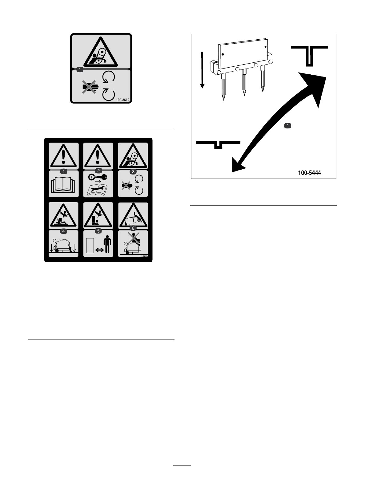
100-3612
1. Entanglement hazard—stay away from moving parts
100-3615
1. Warning, read the Operator’s Manual
2. Remove the ignition key and read the instructions before
servicing or performing maintenance.
3. Entanglement hazard—stay away from moving parts.
4. Crushing hazard of hand and body—lower machine to the
ground.
5. Crushing hazard of hand and foot—keep bystanders a safe
distance from the machine.
6. Falling hazard—do not carry passengers.
100-5444
1. Raise or lower to adjust depth height

7
Specifications
General Specifications–660 Aerator
Working Width 60” (1.5 m)
Overall Width 72” (1.83 m)
Overall Length 33” (.84 m)
Overall Height 34” (.86 m)
Number of Tine Heads 6
Roller Diameter 6” (152 mm)
Weight 1,220 lbs. (554 Kg)
PTO Speed 540 rpm
Power Requirement 24 hp (17.5 Kw)
Hitch Category Category one, three point linkage
Min./Max. Depth 0” – 4” (0–105 mm)
Drive Belt Section 5VX (3) / Tine Pair
General Specifications–880 Aerator
Working Width 80” (2m)
Overall Width 92” (1.83 m)
Overall Length 33” (.84 m)
Overall Height 34” (.86 m)
Number of Tine Heads 8
Roller Diameter 6” (152 mm)
Weight 1,570 lbs. (640 Kg)
PTO Speed 540 rpm
Power Requirement 32 hp (23 Kw)
Hitch Category Category one, three point linkage
Min./Max. Depth 0” – 4.2” (0–105 mm)
Drive Belt Section 5VX (3) / Tine Pair

8
Performance Specifications
mph
(km/hr)
Forward
Hole
Spacings
Lateral Hole
Spacing
Mini Tine
Lateral Hole
Spacing
4 Tine Head
Lateral Hole
Spacing
3 Tine Head
Sq. ft. / Hr.
(Sq. m / Hr.)
660
Sq. ft. / Hr.
(Sq. m / Hr.)
880
0.6 (1) 1” (25 mm) 1.2” (30 mm) 2.4” (62 mm) 3.2” (81 mm) 15,385
(1,403)
20,513
(1,871)
0.8 (1.3) 1.5” (38 mm) 1.2” (30 mm) 2.4” (62 mm) 3.2” (81 mm) 23,008
(1,877)
30,677
(2,503)
1.1 (1.7) 2” (51 mm) 1.2” (30 mm) 2.4” (62 mm) 3.2” (81 mm) 30,769
(2,858)
41,025
(3,811)
1.4 (2.3) 2.5” (64 mm) 1.2” (30 mm) 2.4” (62 mm) 3.2” (81 mm) 38,531
(3,579)
51,375
(4,772)
1.7 (2.7) 3” (76 mm) 1.2” (30 mm) 2.4” (62 mm) 3.2” (81 mm) 46,015
(4,274)
61,353
(5,699)
2.0 (3.2) 3.5” (89 mm) 1.2” (30 mm) 2.4” (62 mm) 3.2” (81 mm) 53,777
(4,995)
71,703
(6,660)
2.2 (3.5) 4” (102 mm) 1.2” (30 mm) 2.4” (62 mm) 3.2” (81 mm) 61,261
(5,690)
81,681
(7,587)
2.5 (4) 4.5” (114 mm) 1.2” (30 mm) 2.4” (62 mm) 3.2” (81 mm) 69,300
(6,437)
92,400
(8,583)
Note: Performance specifications shown are maximum values obtained at rated (540 rpm) PTO speed. Changing engine /
PTO rpm in any particular gear (or fixed hydrostatic pedal position) will not change forward hole spacings, although mph
and productivity specifications will be proportionately changed.
9
Setup
Note: Determine the left and right sides of the machine from the normal operating position.
Loose Parts Chart
Note: Use this chart as a checklist to ensure all parts necessary for assembly have been shipped. If any of these parts are
missing, total setup cannot be completed.
Description Qty. Use
PTO drive shaft 1Transfers power from tractor to aerator
Rear castor/safety shield 1Support aerator for maintenance/storage
Side guards 2Keeps hands and feet away from tines
Keys 2 For hood latch on TE models
Operator’s Manual 2Read before operating machine
Parts Catalog 1Service part identification
Tractor Requirements
•24 horsepower—660
•32 horsepower—880
•Correct tire pressure
•Category one 3 point hitch, rated to lift at least a
1400 lb. (637 Kg) implement–660
•Category one 3 point hitch, rated to lift at least a
1700 lb. (771 Kg) implement–880
•540 rpm tractor PTO
•Adequate front-end weight (ballast)
Ballast Requirements
To help prevent bodily injury and provide added
stability, make sure front of the tractor is
equipped with proper ballast. Refer to tractor
operator’s manual for ballast requirements.
Caution
•Refer to Tractor Operator’s Manual for ballast
requirements.
Connect Lower Link Arms
1. Aerator must be positioned on a flat, level surface for
installation.
2. Back tractor squarely up to aerator until lower link
arms are aligned with hitch pins.
3. Make sure PTO is disengaged.
4. Engage parking brake, STOP engine and remove key
from ignition. Wait for engine and all moving parts to
STOP before leaving operator’s seat on tractor.
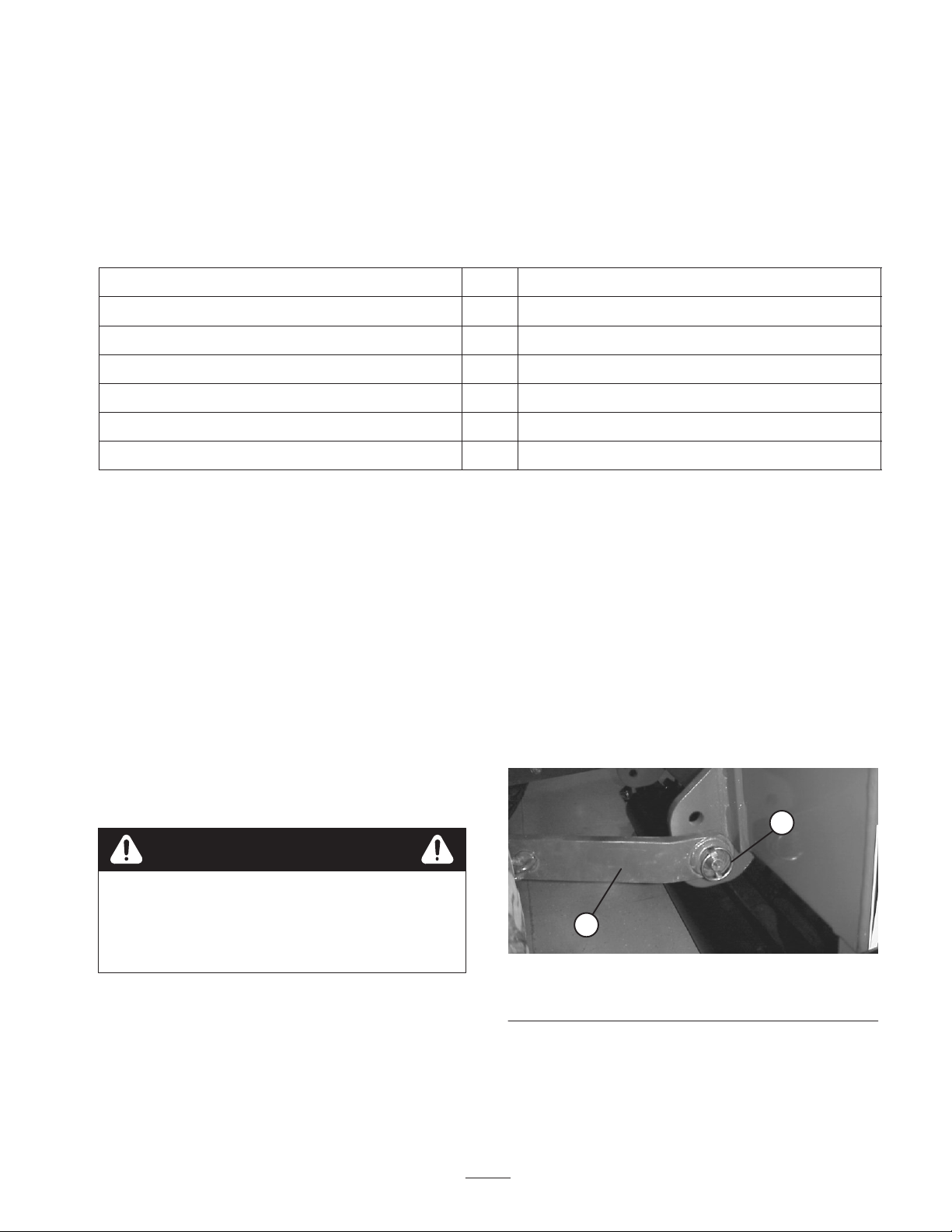
5. Insert right and left lower link arms onto hitch pins
(Fig. 2).
1
2
Figure 2
1. Lower link 2. Lynch pin
6. Secure lower link arms to hitch pins with lynch pins
(Fig. 2).

10
Connect Upper Link
Note: Front of aerator must be vertical or angle forward
slightly while operating for best aeration hole quality
(Fig. 3).This angle will change when depth adjustments
are made. Adjust upper link to control this angle. Refer to
Operation, page 17 for additional information.
90_
0–8_
Operating
Range
Figure 3
1. Connect upper link to lower hole in bracket and secure
with link pin and lynch pin (Fig. 4).
1
2
3
Figure 4
1. Upper link
2. Link pin
3. Lynch pin
2. Rotate adjusting link to tighten the link. Do not
overtighten to raise the back end of the aerator off the
ground.
3. Tighten lock nut to secure upper link into position.
Install Side Guards
1. Remove 4 nuts, lockwashers and washers loosely
secured to each bottom end of aerator frame.
2. Position appropriate side guard (left or right) onto
mounting studs (Fig. 5).
1
Figure 5
1. Side guard (LH)
3. Secure each side guard to mounting studs with washers
and nuts previously removed.
Adjust PTO Shaft Length
Important A long PTO shaft is supplied with machine
to accommodate large variations in the tractor’s PTO and
3 point locations. For most tractors this shaft is too long
and must be cut to correct length or gearbox damage may
result.
1. With the aerator vertical or angled slightly forward,
lower the aerator until the gear box shaft is
approximately the same height as the tractor PTO
shaft. This is the shortest distance between the two
shafts.
2. Measure the distance from the lock groove of the
tractor PTO shaft to the lock groove of the aerator
gearbox PTO shaft. Record this dimension.
3. Fully collapse PTO shaft and measure the distance
between the lock pin collars. Record this dimension.
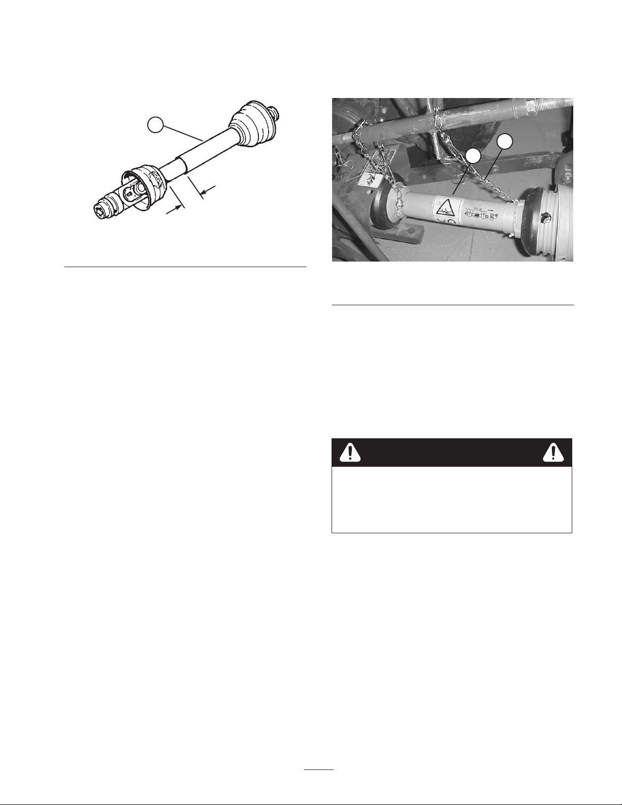
4. At it’s shortest length, the two halves of the PTO shaft
must have at least 1.5 inches (37 mm) of additional
clearance to collapse (Fig. 6). If the dimension in step
2 is not at least 1.5 inches (37 mm) greater than the
11
dimension in step 3, the PTO shaft is too long, proceed
to step 5. If there is enough clearance to allow PTO
shaft to collapse, proceed to step 10.
1.5”
(37 mm)
1
Figure 6
1. PTO shaft
5. Use the following calculation to establish how much
shorter the shaft must be, when connected, to ensure a
clearance of 1.5 inches (37 mm).
A. Subtract the dimension recorded in step 3 from the
dimension recorded in step 2. Record this
dimension.
B. Subtract the result in step 5A from 1.5” (37mm).
The PTO shaft must be shortened by this amount.
6. Using a hacksaw, cut the yellow guards and the steel
tubes shorter by the calculated length. Cut both halves
of the PTO shaft
7. Deburr ends of steel tubes internally and externally.
8. Remove all debris from tube sections.
9. Grease steel tubes liberally.
10. Assemble PTO shaft and secure to aerator and tractor.
11. Measure the shaft. If not at least 1.5 inches (37 mm),
repeat procedure.
12. Raise aerator to highest position. There must be at
least 3 inches (75 mm) of overlap of the halves. Adjust
3 point lift stop, if necessary. Refer to Adjust 3 Point
Lift Stop, page 11.
Connect PTO Shaft
1. Connect PTO shaft to gearbox input shaft (Fig. 7).
1
2
Figure 7
1. PTO shaft 2. Safety chains
2. Connect PTO shaft to rear tractor PTO shaft.
3. Slide PTO shaft forward as far as it will go.
4. Depress pin to secure PTO shaft in place. Slide PTO
shaft back and forth to make sure it is properly locked.
5. Connect shield safety chains from powershaft sections
to welded clips on link arms or to PTO shields. Make
sure chains remain slack when aerator is raised or
lowered.
To help prevent bodily injury, keep all PTO
shields in place and connect shield chains to link
arms or PTO shields to prevent shields from
rotating during operation.
Caution
12
Mount Castor/Safety Stand
Note: Use castor wheel to move aerator around on a hard
surface, as aligning to tractor for installation or for
storage. Level aerator by adjusting roller until the point of
the depth adjustment arrow is just above the side guards.
1. Remove bolt and nut securing rear castor/safety stand
tube to shipping pallet (Fig. 8). Retain bolt and washer
for installation of castor wheel.
1
2
Figure 8
1. Shipping pallet 2. Castor/safety stand
2. Raise aerator off pallet.
3. Remove pallet.
4. Mount castor wheel to rear castor/safety stand tube
with bolt and washer previously removed (Fig. 9).
1
2
Figure 9
1. Castor wheel 2. Castor/safety stand
5. Rear castor/safety stand has two positions:
•Collapsed for aerator storage
•Extended for aerator maintenance
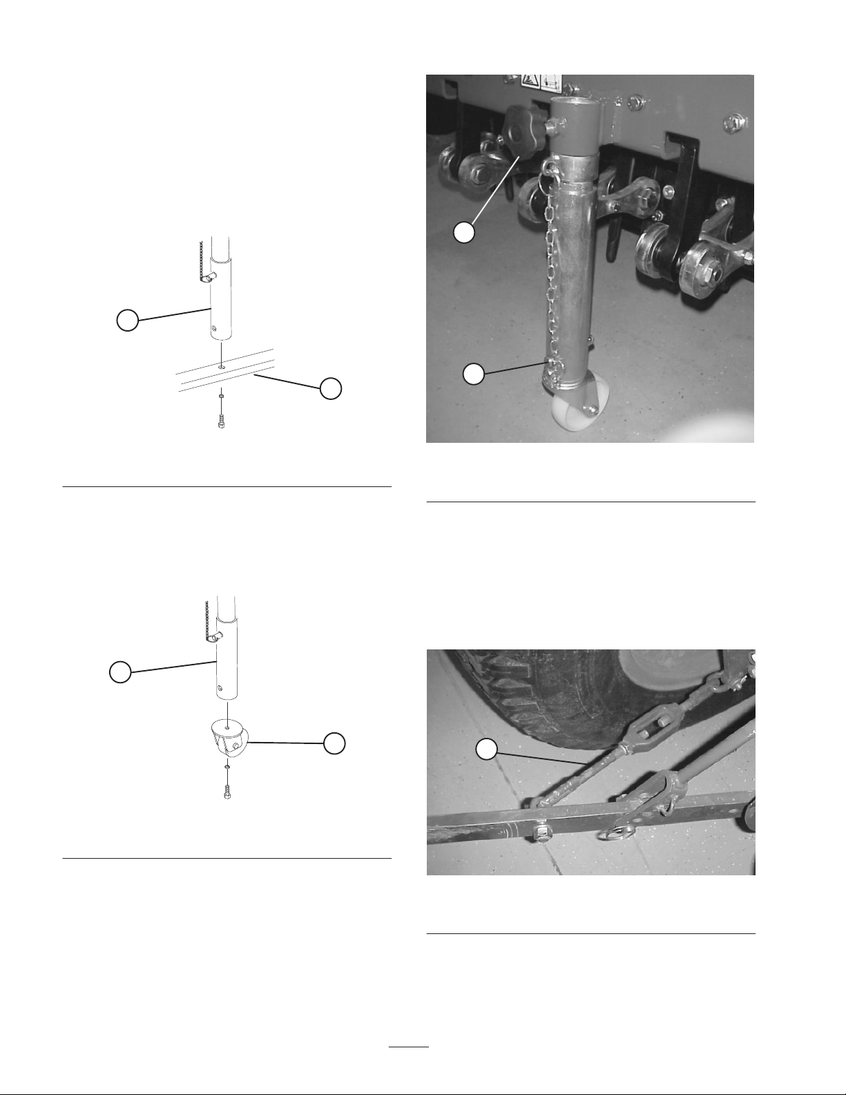
6. Secure castor/safety stand in desired position with pin
(Fig. 10). Tighten castor knob.
1
2
Figure 10
1. Pin 2. Castor knob
7. Slowly lower aerator to the ground.
Adjusting Sway Links
Adjust sway links on lower draft arms of 3-point hitch to
minimize side-to-side sway to a maximum of 1 inch
(25 mm) on each side (Fig. 11).
1
Figure 11
1. Sway link
1. Adjust the lower links inboard until they contact the
aerator mounting plates. This will reduce the stress on
the pins. If the tractor has sway chains instead of sway

13
links, it is recommended that washers be installed
between the lower link arm and lynch pin to reduce the
over hung load on the lift pins.
Note: Refer to tractor operator’s manual for additional
installation and adjustment procedures.
Level Aerator Side–to–side
1. Park tractor and aerator on a level, firm surface. Make
sure both depth gauges are set at the same setting.
2. Place level on top of aerator hood to check for level
side-to-side (Fig. 12).
1
Figure 12
1. Level 2.
3. Turn the adjustable link body (if provided) to raise or
lower the link arm until the aerator is leveled
side–to–side.
Note: Refer to tractor operator’s manual for additional
adjustment procedures.
Adjust 3-Point Lift Stop
Adjust and set 3 point lift stop (Fig. 13) to provide
approximately 4” ground clearance, when in the raised
position, to minimize PTO angle when raising aerator. For
transporting or trailer loading/unloading, the full lift range
can be used as long as the PTO tubes do not slide apart.
Operating the PTO in the fully raised position may
damage the PTO or other components.
1
Figure 13
1. 3-Point lift stop
Note: Refer to tractor operator’s manual for adjustment
procedures.
Install Tines/Tine Heads
A wide selection of tines and tine heads are available for
the aerator. Choose the tine type, size and spacings
required for the job. Install the tine head and tines per
Installation Instructions supplied with each tine kit. Refer
to accessory chart on page 13, for required tines.
Important Never operate the aerator without the
tine heads installed. The arms will move excessively
and may damage the aerator frame.
14
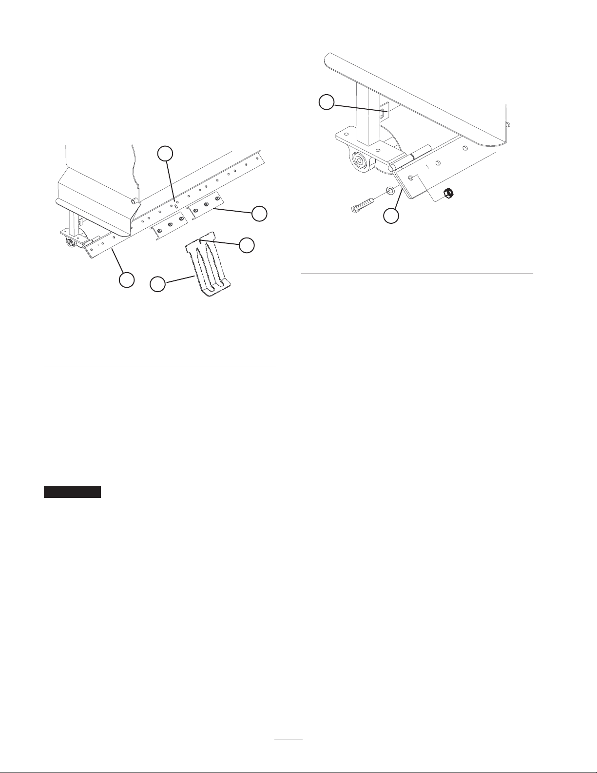
Mount Turf Guards
A wide selection of turf guards are available for the
aerator. Choose the required turf guards per accessory
chart on page 13.
1. Loosen nuts securing turf guard clamps to turf finger
tool bar (Fig. 14).
1
2
3
4
5
Figure 14
1. Turf guard
2. Turf finger tool bar
3. Turf guard clamp
4. Notch
5. Locator key
2. Slide appropriate turf guard under center turf guard
clamp while inserting notch onto locator key of turf
finger bracket (Fig. 14). Refer to accessory chart note,
page 13.
3. Tighten nuts securing turf guard and center turf guard
clamp to turf finger bracket.
4. Working outward, mount remaining turf guards to each
side and secure turf guard clamps.
Important From the rear of the machine, check that
the tines line up with the center of the gaps in the turf
guards.
5. To decrease down pressure of turf guards:
A. Remove nuts securing each end of turf finger
bracket to roller legs (Fig. 15).
1
2
Figure 15
1. Spacer location ( 1 each
end)
2. Roller scraper tab
B. Pivot turf finger bracket upward and insert a
washer onto each stud.
C. Pivot turf finger downward onto studs and check
angle.
D. Install nuts to secure assembly.
Note: Aeration depth may need to be reduced to ensure
clearance between the tine heads and the turf guards.
Check clearance before aerating.
Note: To aid in the loading/unloading of the aerator from
a trailer, remove nuts securing each end of turf finger tool
bar to roller legs and pivot turf finger tool bar upward.
Adjust Roller Scraper
Adjust roller scraper so there is approximately a 1/8”
(3mm) gap between scraper and roller.
1. Loosen fasteners securing each end of scraper to roller
scraper tab (Fig. 14).
2. Slide the roller scraper up or down to required position
and tighten fasteners.
15
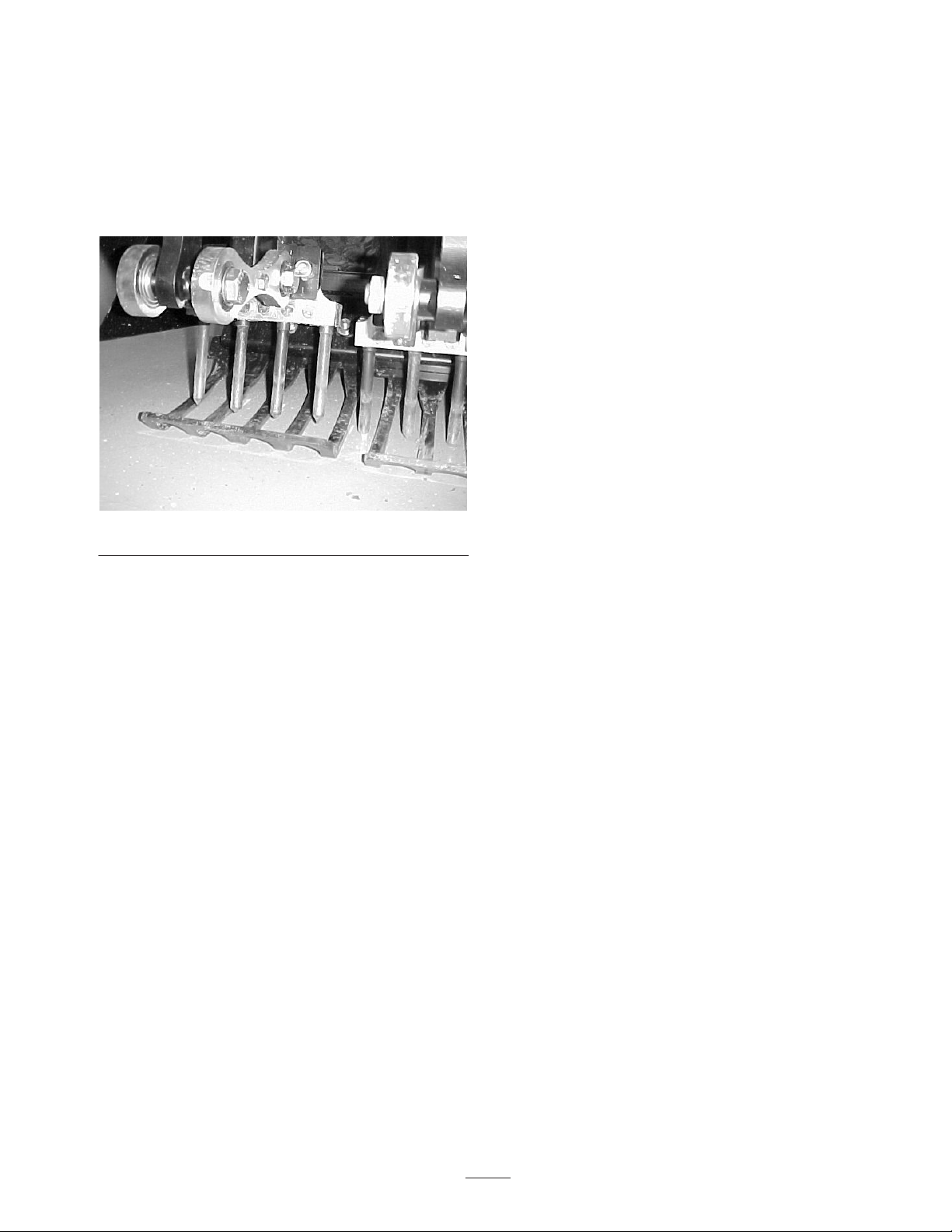
Adjust Turf Guards
Before starting your new aerator, remove the rear castor
stand and lower the machine on the 3–point linkage until
the depth control roller is resting on the ground. From the
rear of the machine, check that the tines line up exactly
with the center of the gaps in the turf guards. Install the
correct turf guards (Fig. 16), if necessary.
Figure 16
Note: Turf with a good root structure may not require the
turf guards. If this is the case. Do not remove the turf
guard tool bar as this adds support to the roller leg
assembly. Just remove the plastic fingers from the turf
guard bracket.
Removing Aerator from Tractor
1. Stop vehicle on a level surface, not on a slope.
2. Disengage the PTO and engage the parking brake.
3. Stop the engine and remove the key from ignition
switch.
4. Before leaving the operator’s seat on tractor, wait for
engine and all moving parts to stop.
5. Install rear castor/safety stand, collapse it to storage
position and install pin. Tighten knob.
Note: Aerator can be stored on original shipping pallet if
desired. Remove castor wheel.
6. Disconnect safety shield chains from PTO tractor.
Secure end of chain to aerator side of PTO shaft to
prevent PTO shaft from coming apart.
7. Slowly lower aerator until rear castor/safety stand
contacts ground.
8. Lower roller, by adjusting depth control handles, until
roller contacts ground.
9. Loosen locking nut and rotate adjusting link to release
tension between aerator and tractor.
10. Remove lynch pin and top link pin securing center link
to bracket.
11. Push release pin to disconnect powershaft from tractor
PTO shaft.
12. Slide powershaft back and remove from tractor.
13. Remove lynch pins and slide lower link arms off hitch
pins.
16
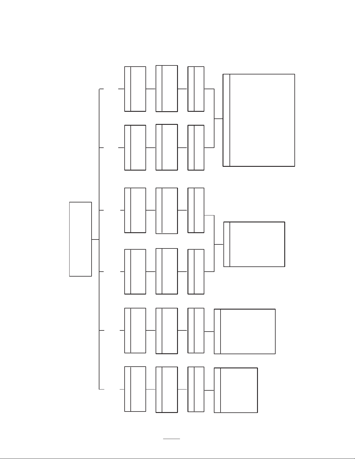
Accessory Chart
.75” (19 mm)
Side Eject
Tine=92-7900
6 Required
Model No. 09720
Heads Required
4 Tine Heavy
Duty Head
(2.4” spacing)
3 Tine Heavy
Duty Head
(3.2” spacing)
8 Mini Tine
Head
(1.2” spacing)
6 Needle Tine
Head
(1.6” spacing)
3 Tine Head
(3.2” spacing)
4 Tine Head
(2.4” spacing)
Heads Required Heads Required Heads Required Heads RequiredHeads Required
6 Required
Model No. 09721
6 Required
Model No. 09733
6 Required
Model No. 09734
6 Required
Model No. 09722
6 Required
Model No. 09723
Turf Guards Required
6 x #100-5418
1 x #100-5419*
Turf Guards Required
1 x #100-5420*
8 x #100-5421
Turf Guards Required
2 x #100-5414
3 x #100-5415*
Turf Guards Required
5 x #100-5416
Turf Guards Required
2 x #100-5414
3 x #100-5415*
Turf Guards Required
5 x #100-5416
Heads RequiredHeads Required
Tines Required
36 Required
Tines Required
48 Required
Tines Required
18 Required
Tines Required
24 Required
Tines Required
18 Required
Tines Required
24 Required
Tine Options
.20” (5 mm)
Needle
Tine=100-3620
.31” (8 mm)
Needle
Tine=100-3621
.37” (9.5 mm)
Mini Solid
Tine=100-3622
.25” (6.5 mm)
Side Eject
Tine=94-3417
Tine Options
.83” (21 mm)
Side Eject
Tine=104-9877
.75” (19 mm)
Hollow
Tine=86-9720
Tine Options
.35” (9 mm) Solid Tine=#100-3626
.39” (10 mm) Solid Tine=#100-3627
.43” (11 mm) Solid Tine=#100-3628
.51” (13 mm) Solid Tine=#100-3629
.63” (16 mm) Solid Tine=#100-3630
.39” (10 mm) Hollow Tine=#100–3633
.51” (13 mm) Hollow Tine=#100-3634
.63” (16 mm) Hollow Tine=#100-3635
.63 (16 mm) HD Side Ejection Hollow
Tine=104-9876
.75” (19 mm) HD Side Ejection Hollow
Tine=#104-9875
Tine Options
.20” (5 mm)
Mini Side Eject
Tine=100-3625
ProCore 600 Aerator
Model Number 09701
Model Number 09701TE
Note: One of these turf guards must be installed in center position.
17
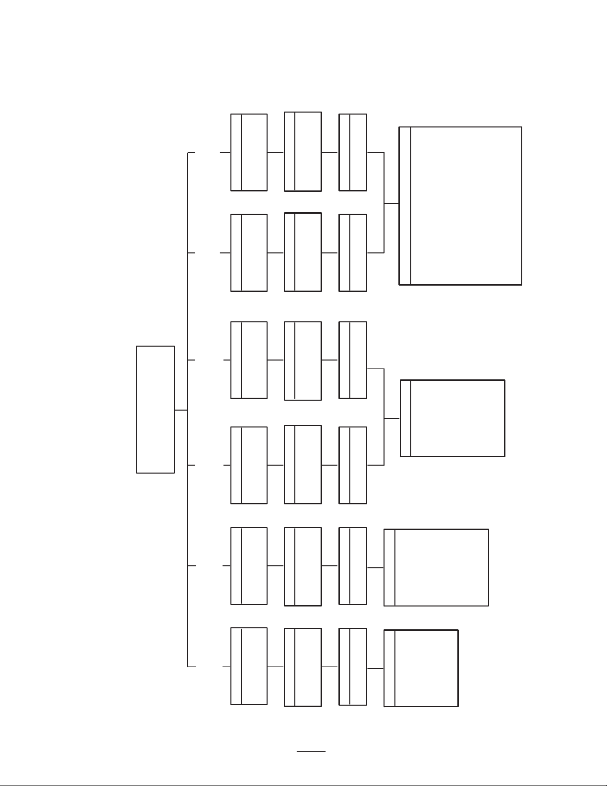
Accessory Chart
.75” (19 mm)
Side Eject
Tine=92-7900
8 Required
Model No. 09720
Heads Required
4 Tine Heavy
Duty Head
(2.4” spacing)
3 Tine Heavy
Duty Head
(3.2” spacing)
8 Mini Tine
Head
(1.2” spacing)
6 Needle Tine
Head
(1.6” spacing)
3 Tine Head
(3.2” spacing)
4 Tine Head
(2.4” spacing)
Heads Required Heads Required Heads Required Heads RequiredHeads Required
8 Required
Model No. 09721
8 Required
Model No. 09733
8 Required
Model No. 09734
8 Required
Model No. 09722
8 Required
Model No. 09723
Turf Guards Required
7 x #100-5419
Turf Guards Required
5 x #100-5420*
4 x #100-5421
Turf Guards Required
5 x #100-5414
Turf Guards Required
1 x #100-5416*
4 x #100-5417
Turf Guards Required
5 x #100-5414
Turf Guards Required
1 x #100-5416*
4 x #100-5417
Heads RequiredHeads Required
Tines Required
48 Required
Tines Required
64 Required
Tines Required
24 Required
Tines Required
32 Required
Tines Required
24 Required
Tines Required
32 Required
Tine Options
.20” (5 mm)
Needle
Tine=100-3620
.31” (8 mm)
Needle
Tine=100-3621
.37” (9.5 mm)
Mini Solid
Tine=100-3622
.25” (6.5 mm)
Side Eject
Tine=94-3417
Tine Options
.83” (21 mm)
Side Eject
Tine=104-9877
.75” (19 mm)
Hollow
Tine=86-9720
Tine Options
.35” (9 mm) Solid Tine=#100-3626
.39” (10 mm) Solid Tine=#100-3627
.43” (11 mm) Solid Tine=#100-3628
.51” (13 mm) Solid Tine=#100-3629
.63” (16 mm) Solid Tine=#100-3630
.39” (10 mm) Hollow Tine=#100–3633
.51” (13 mm) Hollow Tine=#100-3634
.63” (16 mm) Hollow Tine=#100-3635
.63 (16 mm) HD Side Ejection Hollow
Tine=104-9876
.75” (19 mm) HD Side Ejection Hollow
Tine=#104-9875
Tine Options
.20” (5 mm)
Mini Side Eject
Tine=100-3625
ProCore 880 Aerator
Model Number 09702
Model Number 09702TE
Note: One of these turf guards must be installed in center position.
18
Controls
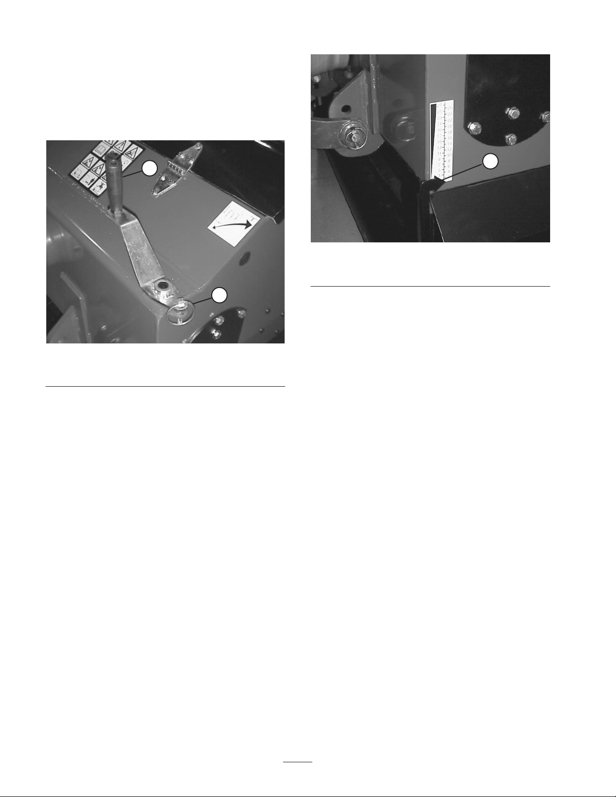
Depth Adjustment Handles
Remove lynch pins, rotate handles to raise or lower tines
to desired depth and replace lynch pins (Fig. 17).
1
2
Figure 17
1. Depth adjustment handle 2. Lynch pin
Depth Guides
Depth guides (1 thru 27) are provided to give equal
increments for adjustment. The numbers do not relate to
measurements of depth as this changes with tine type and
amount of tine wear. Adjustment between two numbers
will give approximately .20 inches (5 mm) change in
depth. The higher the number, the deeper the tine
penetration. Always adjust each side to the same number
(Fig. 18).
1
Figure 18
1. Depth guide

19
Operation
Adjust Tine Depth
To adjust the working depth of the tine, proceed as
follows:
1. Remove the lynch pin from each depth adjust handle
(Fig. 19).
1
Figure 19
1. Depth adjustment handle
2. Turn the depth adjuster handles to raise (deeper) or
lower (shallow) the roller.
Note: Make sure that the roller is on the ground once the
depth is chosen.
3. Depth guides (Fig. 20) are provided with numbers 1
through 27. Depth varies with the mounted angle of
aerator, tine type and amount of tine wear. Refer to
Depth Chart on page 16. Adjustment between two
numbers will give approximately 0.20 inches (5 mm)
change in depth. The higher the number, the deeper the
tine penetration. Always adjust each side to the same
number.
1
Figure 20
1. Depth guide
Important If a large change in height is required,
adjust each leg by a small amount to ensure the roller legs
are adjusted as evenly as possible.
Note: Remember when depth changes are made, you will
need to adjust the top link length to give the correct
machine angle. Refer to Connect Upper Link, page 8.
Important Tine depth is affected by the mounted
angle of the aerator as well as the depth setting. If the
aerator is angled rearward, the tine heads may contact the
turf guards and damage may occur. Depths 26 & 27
cannot be used when the aerator is in the vertical position.
See Depth Chart.
4. Install the depth adjust handle lynch pins before
running the machine, even if you are just testing for
correct depth.
Important Tine depth is determined by the tine type,
depth adjustment, amount of tine wear and mounted angle
of the aerator. Refer to Depth Chart on page 18.
Important Maximum depth is achieved when the
aerator is mounted vertically (Fig. 21) and the depth
adjustment set at 25. In this condition, do not operate at
greater depth settings, as there is minimal clearance
between the tine head and the turf guards. Never operate
with the aerator angled rearward or damage to the turf
guards may occur.
20
90_
Figure 21
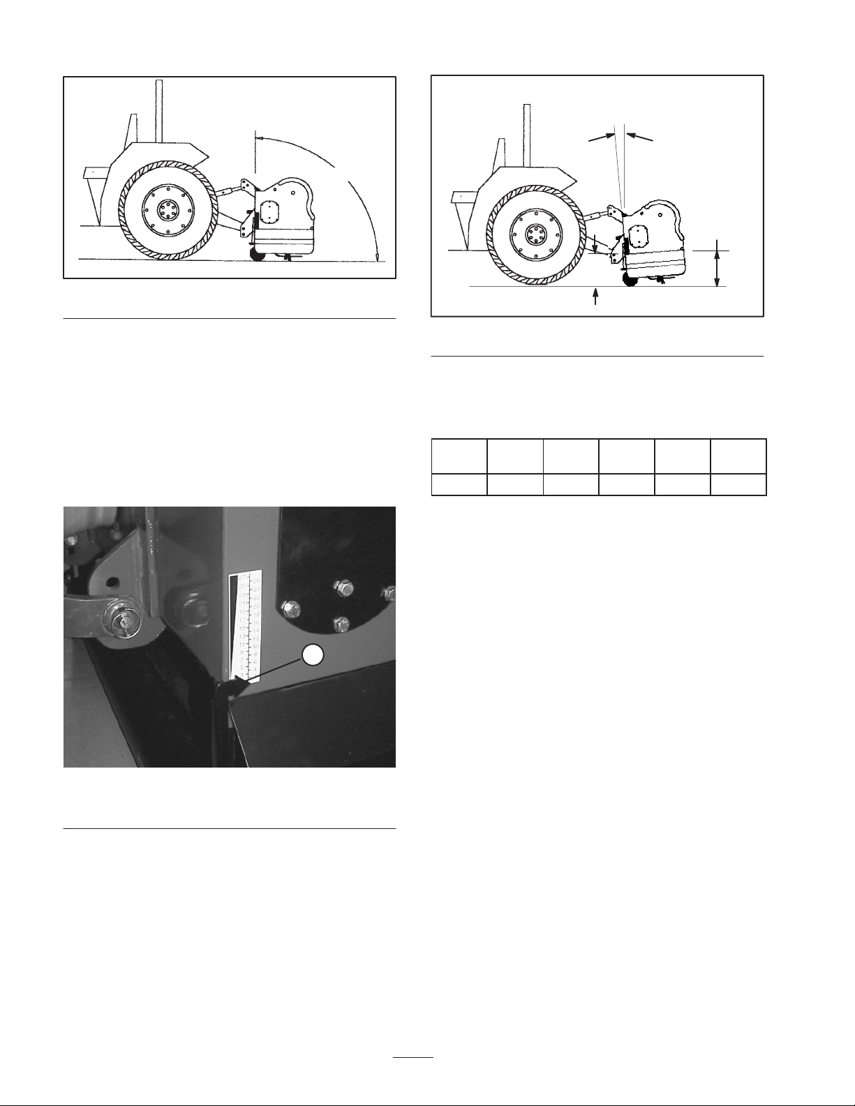
In some instances, angling the aerator forward may
improve hole quality but will also reduce aeration depth
and gain clearance with the turf guards. A forward angle
of approximately 4_is a good initial setting. Use a
magnetic based angle indicator to determine the forward
angle, or use the following procedure:
A. Position aerator on a flat level surface.
B. Make sure aerator roller is on the ground and depth
indicator is set at desired setting (Fig. 22).
1
Figure 22
1. Depth guide
C. Measure and record the distance from the ground
to the lower rear corner of the frame (“H1”) and
front corner of the frame (“H2”) (Fig. 23).
4_
“H1”
“H2”
Figure 23
D. Adjust upper link until the difference between
“H1”–“H2” matches desired forward angle of
aerator (See Angle Chart below).
“H1”–
“H2”
0” 0.8”
(21mm)
1.7”
(43mm)
2.5”
(64mm)
3.3”
(85mm)
Angle 0_2_4_6_8_
This manual suits for next models
5
Table of contents
Other Toro Tiller manuals

Toro
Toro 58602 User manual

Toro
Toro 09802 HydroJect 3010 User manual

Toro
Toro GREENS AERATOR 09120 User manual

Toro
Toro 58604 User manual

Toro
Toro Soil Cultivator User manual

Toro
Toro 23515 User manual

Toro
Toro 23518 User manual

Toro
Toro 23516 User manual

Toro
Toro 22542 User manual

Toro
Toro 58601 User manual


Popular Tiller manuals by other brands


TARAL
TARAL 16M owner's manual

Craftsman
Craftsman Incredi-Pull 316.292621 Operator's manual

Ryobi
Ryobi RY36CVXA manual

Meccanica Benassi
Meccanica Benassi MTC 601 Use and maintenance manual

IVT
IVT GTIL-63R-RC instruction manual

White Outdoor
White Outdoor Roto Boss 850 215-418-190 Parts list and instruction manual